GENERAL
From the book "Ships of Canada's Naval Forces" :
"In 1919 a hydrofoil craft developed by Alexander Graham Bell and F.
W. Baldwin attained the unheard of speed of 60 knots in trials on Cape
Breton's Bras d'Or Lake. It was pow-ered by two aircraft engines and air
propellers. The potential of such a craft as an A/S vessel was finally
considered in the early 1950s, when a small test vessel was built in Britain
to Naval Research Establishment specifications. It arrived at Halifax aboard
HMCS Bonaventure in 1957, and its performance led to the awarding of a
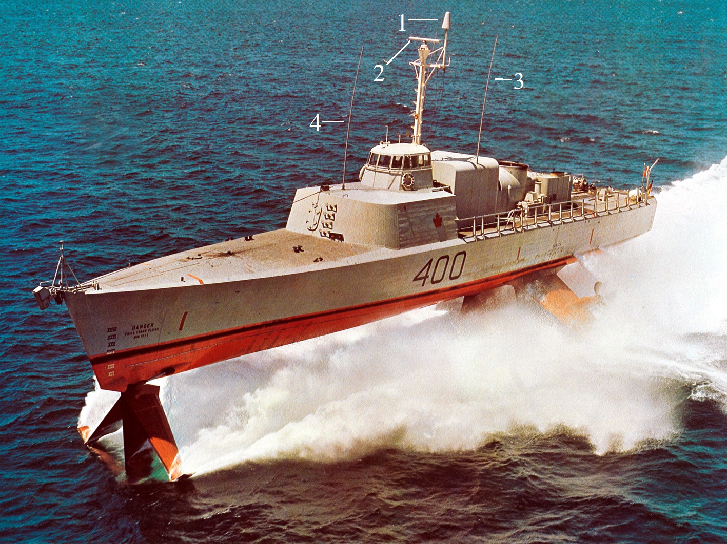
contract to DeHavilland Aircraft of Canada in 1963. HMCS Bras d'Or, named
for the scene of the first tests and designated a fast hydro-foil escort
(FHE), was commissioned in 1968. When "hull-borne" at low speeds, the craft
is driven by a 2,400 BHP diesel engine, but at about 23 knots the foils
lift the hull clear of the water, and propulsion is taken over by a 30,000
SHP gas turbine engine powering twin screws. Trial speeds as great as 63
knots were attained. Despite the evident success of the prototype FHE,
she was laid up in 1971 and, in 1982, presented to the Bernier Maritime
Museum at L'Islet-sur-Mer, Quebec , on the St. Lawrence River below Quebec
City'"
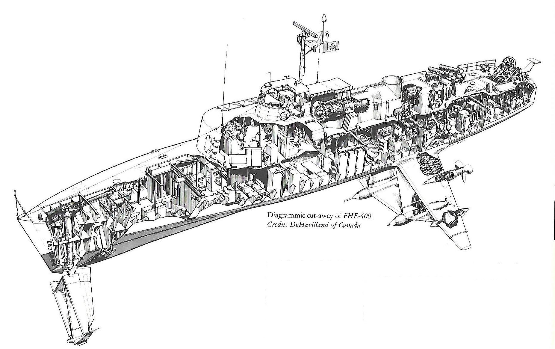
Extracts from the book "The Flying 400" by Thomas Lynch provide
an overview into the ships electronics and systems.
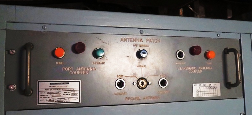
COMMUNICATIONS
Although a comprehensive sensor fit was planned and built for FHE-400,
only the Phase I fit was ever implemented. This included a communications
fit, intercom, radar, gyro-compass, Decca navigator and echo sounder. For
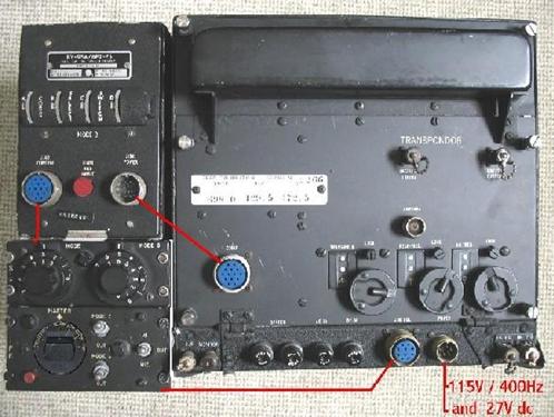
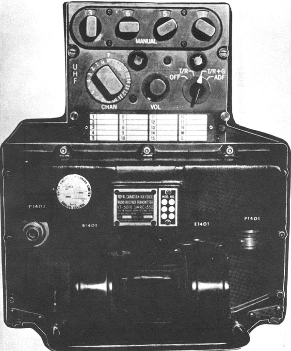
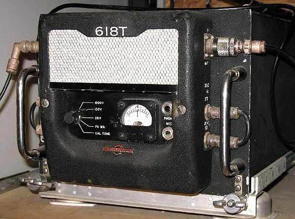
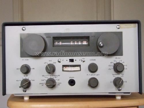
communications, there were two single-sideband (SSB) , high-frequency
transceivers and one ultra-high frequency transceiver fitted aboard the
ship . Destroyer-type whip antennae were found to be too short for the
lower frequencies of the HF set, thus stressing the antenna-matching
components to their maximum limits. The HF antennae were eventually replaced
in April, 1971 after corrosion made the old ones nearly useless. The Fleet
communication fit of radioteletype and second UHF set was not made. These
sets were supplied by Collins Radio on February 15, 1966 at a cost of $17,946.
Pat Barnhouse adds this about communications:
"I can confirm that the whip antennas were 25 foott fibreglass.
I do not remember if they were built by Andrews or Valcom.but there was
difficulty when tuning in the lower HF range.
My instinct is that it was Andrews. I remember the first version
of the whip being wind and ice-load tested at NETE. That version
was very limp. Subsequent design changes made it more sturdy.
The 25 foot length was rather short for the lower frequencies of
the HF and in the hydrofoil, the difficulty of tuning to low frequencies
was compounded by the whips being secured to the inner cowling of the gas
turbine housing. This resulted in a lack of ground plane and made
the antennas half wavelength rather than one quarter wavelength.
My suggestion of a grounding strap from the base of the antennas to the
outside cowling was rejected by deHavilland as not suitable for their
ship"
RADAR
The selection of appropriate radar began in 1963, with searches conducted
in the UK and the USA. However, nothing suitable for the ship was found
in these countries. Weight was a prime factor, as well as performance,
resistance to shock failure, robustness of the scanner head, versatility
and availability of parts. It was finally decided in 1965 that the best
of the two finalists was the type 8GR300-03A (or is it 8GR300-4?) X-band
surveillance radar originally made by NV Hollandse Signaalapparaten of
Holland. The company was swallowed up by several mergers (Phillips being
one of them) and is now called Thales Nederland. Without modification,
the 8GR-300 was purchased by Canadian Westinghouse for $82,000 from Philips
Sweden.
Modifications were made by Canadian General Electric to allow integration
with the AIS (Action Information System) including the provision
for repeaters on the bridge and the AIS, but the latter was never fitted.
The radar performed admirably, with only minor clutter observed on the
screen during rough weather. One major glitch occurred in 1970 with the
near loss of the scanner head when the mounting bolts were sheared off.
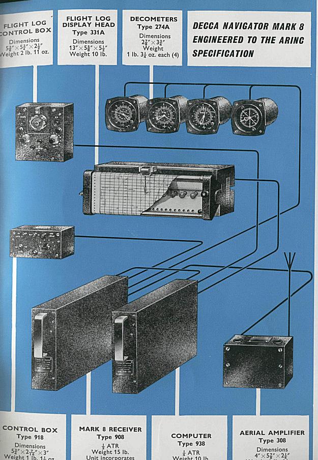
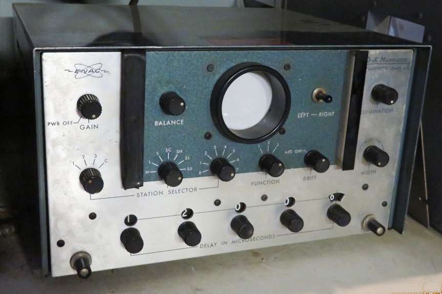
NAVIGATION
A Decca Navigator system (Mk 8) with a Mk 23 gyro repeater was fitted
aboard the hydrofoil thus providing satisfactory fixes until late
in 1970 when errors of one mile threw serious doubts regarding the
reliability of its bearings. Ultimately the problem was traced to electrical
interference.
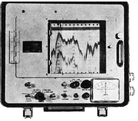
The T1 echo sounder (or was it the model 9006?) produced fair
results , however, returning echoes were masked by acoustic wash any
time the ship was travelling at speeds of higher than 4 knots. That made
it only suitable for spot checks.
A Pelorus , fitted on the bridge, made visual navigation easy during
daylight hours. It could be swung out of the way against the bridge's
deckhead, just abaft of the windows. However, navigation was limited by
the bridge structure supports and when foil-borne, FT4 turbine stack effluent
masked the whole stern horizon. It made astral fixes nearly impossible.
Hence, navigation was largely done by Decca and the radar set.
Night navigation was limited by the bridge structure supports towards
the stern and when foil-borne, FT4 stack effluent masked the whole stern
horizon and made astral fixes next to impossible. Hence, navigation
was largely done by Decca and the radar set. There were no provisions made
for lookouts, which showed that a seaman or serving officer hadn't
been consulted in the design phase!
FIGHTING EQUIPMENT
This project was broken down into two phases. Phase I of the Fighting
Equipment called for the installation of the radar, navigation equipment
and intercom, all of which were provided in late 1966. Phase Ii called
for the installation of the Action Information Centre, software, integration
of the AN/SQS-507 sonar and Phillips radar into this system. It would also
integrate ASW torpedo ballistics computation and arming, etc
Phase I saw numerous uses throughout the trials of 1968-71, but the
Phase II equipment never made it past the Maritime Warfare School. The
completed AIS system was installed at the Maritime Warfare School by Cameron
Windows Ltd., under a contract dated April 30 1968 for $3,843.27 Additionally,
the AIS Hughes display equipment was purchased from the USN at a cost of
$594,700 under a contract dated July 3, 1968.
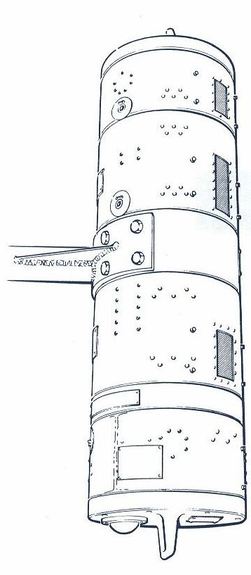
Sonar: with an established need for a lightweight variable depth sonar,
it was only natural to turn to Canadian Westinghouse for assistance in
design, since they had been instrumental in the nearly-finished design
and construction of the AN/SQS-504 and 505 VDS sonar arrays for conventional
frigates and destroyers.
Torpedo tubes: Originally four groups of three Mk.32 lightweight torpedo
tubes were to be installed. This was later changed to two fits of triple
tubes with Mk.46 torpedoes, angled at 90° to the ship's centreline
and angled downward. A limiting sensor was developed to inhibit firing
a torpedo when ship roll made the torpedo entry angle too oblique. This
system although complete, was not fitted. Overall this was an entirely
separate program from the actual construction of Bras Dor.
FATE
The fate of Bras Dor is well summarized in the book The Flying
400.
"With the Bras D'or project cancellation and the Naval
and DeHavilland personnel reeling in shock, National Defence Headquarters
rapidly made plans to decommission the ship. Cdr. Ian Sturgess was
given orders to begin posting some of the crew ashore for retraining and
deployment to other ships in the fleet.
Remaining crew members would be utilized in preparing the ship for its
five year 'hibernation'. Starting just after the New Year, 1972, the pace
of preparation accelerated. The turbine engine was drained of oil and inhibited
against corrosion and weathering. The fuel tanks were drained and steamed
clean of sludge; the hydraulic systems were drained and sealed. Electrical
circuits were coated and slowly the electronics were sealed against dust
with plastic wrap and duct tape. There were a thousand
and one small things that had to be done by the skeleton crew.
By May 1, the major inhibiting efforts were complete. In a final ceremony
the ship was officially decommissioned. A small group of officers and men
trooped aboard the hydrofoil which was perched atop her transport
barge. Facing toward the mast, they watched as the Canadian flag and the
small commissioning pennant were slowly lowered for the last time.
After the decommissioning, the preservation procedures continued.
After the ship had been thoroughly mothballed, she was vacuumed
to remove as much dust as possible from the hull. Next, Shell VPI-260 was
brought aboard. This was a vapor phase corrosion inhibitor. VPI 260 forms
a thin protective layer on the surface of the metal which minimizes the
transmission of moisture and oxygen. The hatches were then sealed and tamper-proof
seals applied to the dogs to prevent entry. The bow foil was enclosed in
a climate-controlled enclosure of plywood . The anhedral foil tips were
removed and crated, as were the propellers. Then, the entire main foil
structure and the FT4 housing were enclosed in a climate-controlled shelter
and the ship, on its barge, was moved to Jetty Nine, the farthermost corner
of the Halifax Dockyard, to await her final outcome. She sat, neglected,
in this state with her only visitors being CFAV watch-keepers until
1976. By this time it was known by all that the ship would never be re-activated
and the ship was unsealed.
Slowly, items that were declared to be surplus disappeared from
the ship and handed over to Crown Assets for disposal. Over 1,500
spare parts were inventoried and declared surplus and sold for scrap value.
The super-cavitating propellers which had cost nearly $750,000 to design,
build and use were sold as scrap.
Bunks, microwave ovens, freezers, radios, and electronic gear had been
stripped and sold by this time. The Paxman diesel had been removed years
before in 1971. Neglect was everywhere. Shortly thereafter, Bras d'Or was
moved to Jetty Six, the old Naval Armament Depot Wharf in Dartmouth. Here
the dismantling began in earnest in 1981-82. The turbine was spirited away
to DRB facilities in Quebec. By April, 1983, the destruction of the ship's
interior was in its last stages, with the engine room a mass of tangled
stainless steel piping, slippery with red hydraulic oil, making the ship
appear to have bled to death. It had been stated that Bras d'Or had been
offered to various museums over the years, however the estimated cost of
$1 million to set up the ship as a practical exhibit had scared off any
potential takers. Eventually the ship was presented to the Bernier
Maritime Museum at L'Islet-sur-Mer, Quebec , on the St. Lawrence River
just below Quebec City'"