The CPRC-26 was a self-contained, battery operated, transceiver (walkie talkie) which operated in the frequency range of 47.0 to 55.4 Mc. Its 300 milliwatt input is frequency modulated using a deviation of +/- 15 KHz. Six, crystal controlled channels were available for communication. Power was provided by a dry battery and a fresh unit would provide about 20 hours of service. Normally, the CPRC-26 would be used with a 47 inch collapsible whip antenna. It was a unique set for it's time since it had replaceable modules.
Ray Robinson VK2ILV, an avid radio collector residing in Australia, provides an insight into the methods used by the Australian Army to maintain and test the CPRC-26. " The CPRC-26 VHF radio was used by the Australian Army as a VHF backpack. AWA (Amalgamated Wireless Australia) at their Military Electronics Division in Sydney, had the repair contract from the Army, including sets that were returned from Vietnam. I recently spoke to a technician who worked on these sets in the approximate period from 1964 to 1967.
He was working on these sets by himself, and there were others working on other army sets. He would call in the boss or the others if a set proved troublesome. They came in batches, varying from 10 sets to 50 sets. Generally, they were complete with whips, handsets, bags and instruction plates. These were supplied if missing, and the sets left complete, and ready to use, with fresh batteries. He could average 5 repairs a day.
The test equipment used was not very specialized. Maintenance types used an AWA VHF signal generator and an AWA Noise and Distortion meter for testing the receiver. Close at hand was a power output meter and a dummy load for testing the transmitter. A set of meters, mounted on a panel, was used to plug into the radio test socket. A bench power supply was used in place of the battery pack. For most repairs, an ordinary soldering iron was used for heating the bases of the modules. No CTS-3/PRC test set was available for testing the modules, nor a spectrum analyzer for looking the output spectrum and harmonics.
During maintenance, the most common faults were in IF cans for the receiver and the modulator cans for the transmitter. Low transmitter output was usually the output tube (valve). Some resistors under the base plate would go high in value, and sometimes a diode in the discriminator would go out of specification. Failures and problems were usually due to microphonic valves, so the common repair method was to connect up the test equipment and a pair of headphones, and tap or flick the suspected module with your finger, and listen for ringing. The module would be replaced if found to be noisy. Sometimes the module would fail completely after a tap or flick.
Isolating a fault to a particular module was done by trying a suspected
module in a working bench radio, and also by using a known good module
in the faulty radio. When the radios came in for refurbishing or reconditioning,
they were cleaned and checked, and given a new set of modules. Some sets
had broken switches, and split cases. He recalls one set that a bullet
had entered and was still inside. After repair, the sets were heated in
a lamp box, then sealed with a new desiccant inside, and given a final
test. A red seal was placed over the case/front panel join, so that any
tampering could be detected" .
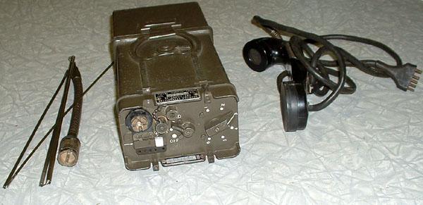 |
| CPRC-26 with collapsible antenna and handset. (Photo by Jerry Proc) |
 |
| Close-up of front panel. (Photo by Jerry Proc) |
 |
| The radio has been separated form the battery compartment (right) . (Photo by Jerry Proc) |
 |
| With canvas carrying case and headphone/ handset accessories |
 |
| This display shows all the CPRC-26 sub-assemblies and accessories. (Photo source unknown) |