 |
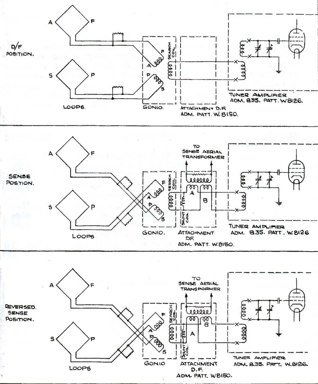
This simple block diagram shows the interconnection
between the B35 receiver, the
DF/sense unit attachment and the goniometer. Click to enlarge. (Extract from Admiralty Book of Instructions for B-35 Tuner-Amplifier) |
Frequency range: 670 KHz to 20 MHz.
Indicating Method: Aural null
Components:According to an equipment manifest "HMCS HAIDA File Number 7400-DDE-215V1" the FH-3 the configuration aboard HMCS HAIDA consisted of the following components.
B35 receiver, AP W8126 s/n MC201371 (a modified Marconi CR100 Type 2 was sometimes
used in place of the normal B-21)
DF/sense unit attachment AP W8150 s/n MC 202512
Goniometer AP 5329A. s/n MC 267
|
This simple block diagram shows the interconnection
between the B35 receiver, the
DF/sense unit attachment and the goniometer. Click to enlarge. (Extract from Admiralty Book of Instructions for B-35 Tuner-Amplifier) |
FH -3 was used with the following Admiralty PAttern receivers - B21, B21A, B21B, B35 and B36. The B21A was the receiver used in the FA4, FC3, FC4 and FC5 versions, which were all variations on a theme. The B23A and B23B are sometimes referred to as HF DF systems, which is incorrect. They were used in MF DF systems FM4, FM7 and FM11.As for FH3 aerials, there were many. In small ships, the FH3 was used the S16 3ft frame coil while larger ships used the S17, a 4.5ft frame coil. Then the S25 was introduced with an integral sense aerial. With the earlier S16, S17, S18 frame coils, a separate vertical wire was used for the sense antenna. However, ASE found that a displaced sense aerial distorted the cardioid polar diagram and introduced errors into the resultant bearings, hence the reason for the introduction of the S25. Meanwhile, FH4 development was well in hand and the S25 was modified to become the S25B that included the test transmission loop. Additional trials with the FH3 showed that the S25B had no negative affects, so later FH3 installations used the S25B frame coil.
Further research by John Wise indicates that at least four aerials were associated with the FH-3 and FH-4 HF DF systems. They are designated S16, S18, S25 and S25B. The only difference between the S16 and S18 is their size. The S16 was crossed diamonds with a 3 foot aperture, usually fitted on top of a pole structure. S18 had a 4.5 foot aperture and was often integrated into a mast structure. The S16 had a short 'spike' on top - this was not a sense aerial but a lightning conductor. S16 was used on corvettes, frigates, destroyers while S18 was fitted to cruisers, carriers, battleships and depot ships.
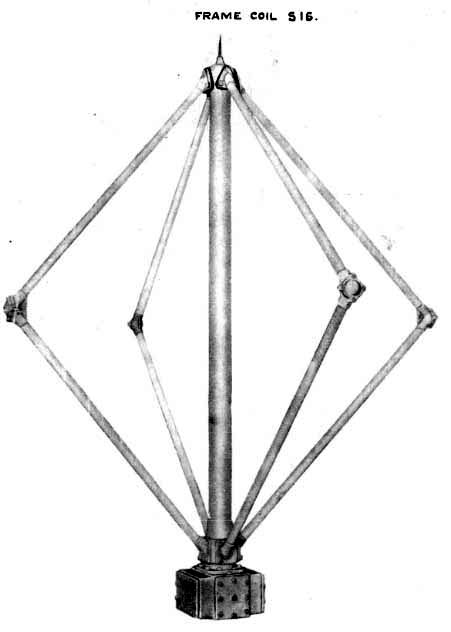 |
| Frame coil S16. (British Admiralty photo) |
Thus, it is very difficult to confirm HF DF installations from photos other than to say that if an S16, S17, S18 or S25 were used, then it had to be an FH3 but if if an S25B was at the masthead it could be either an FH3 or FH4 on the end of it. Meanwhile any warship built with HF DF after mid 1944 would have had the FH4. So photos of ship's DF aerial must be related to ship's building and commissioning dates.
This table of components was derived from a partial FH-3 manual found at HMS Collingwood web site.
| FH-3 PRINCIPAL COMPONENTS | |
| Pattern No. | Description |
| W6118A | Frame Coil S25B |
| W7834 | Junction Box for twin and single cables (4) |
| W1316B | Receiver (Tuner-Amplifier) B21B |
| 1204B | Rectifier - Design B |
| 5329A | Radiogoinometer S29A |
| S5609 | RF Transformer unit- Design 5 |
One document located at HMS Collingwood Museum indicates FH3 had the following components: S18 frame coil, M9, E27, K7, N20 and S29. The meaning of the codes is not known at this time. For whatever reason there is a discrepancy in the frame coil part numbers between the two documents. The information found in the FH-3 manual is assumed to be correct.
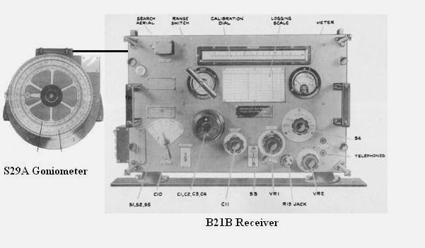 |
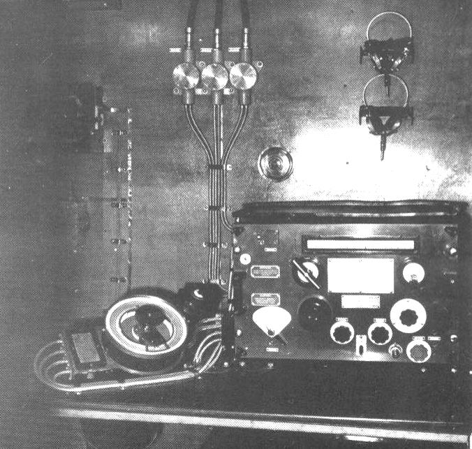
| This is a composite image of the FH-3 outfit based on the components listed in the manual. The key item is the goniometer. (Photo components courtesy British Admiralty) |
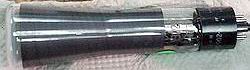
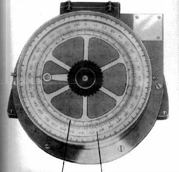 |
| A closer look at the S-29 goniometer. Too bad the photo doesn't show the method of attaching (cable glands vs binding posts) the cables from the loop antennas. (Photo courtesy British Admiralty) |
 |
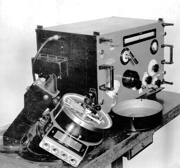
| This photo is titled "FH3" in Arthur Bauer's book but it's likely an American DAR set, an adaptation of the FH-3. The goinometer in the photo is not the S-29 but an exact match to the DAR goniometer in the section below. Also, note the attachment to the upper right corner of the goniometer. It looks like the CRT indicator. (Photo courtesy "Funkpeilung als allierte waffe gegen deutsche U-Boote 1939-1945" by Arthur Bauer) |
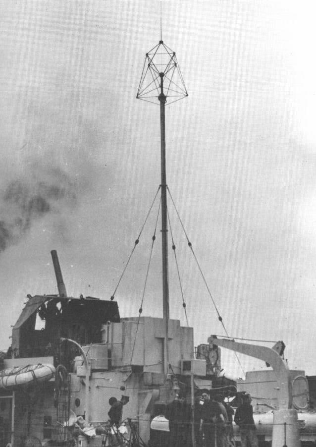 |
| FH3 antenna . (Photo courtesy "Funkpeilung als allierte waffe gegen deutsche U-Boote 1939-1945" by Arthur Bauer) |
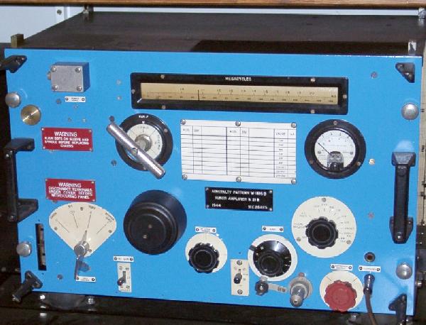 |
| B21B receiver from 1944. Courtesy Signals Collection '40 to '45 web page |
OUTFIT DAR
American DF outfit DAR is included here because its an adaptation of the British FH-3. The DAR manual actually states that.Frequency range: 1000 to 20,000 kHz
Indicating Method: 2 inch CRT to observe signal null.
Circa: 1942
 |
| DAR D/F set. It uses a Type 902 CRT null indicator. There are no loop cables attached. ( Likely a Naval Research Laboratory photo). |
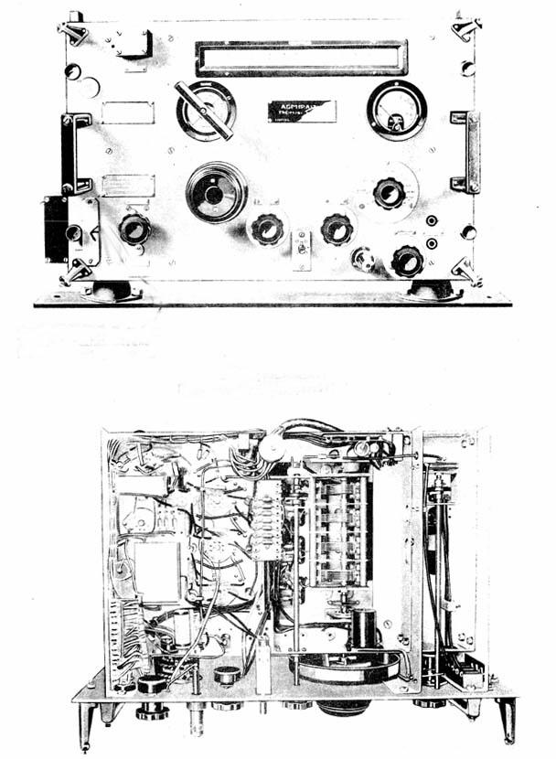 |
| Front and chassis bottom views of the B21 tuner-amplifier. (Photo likely from a British Admiralty publication). |
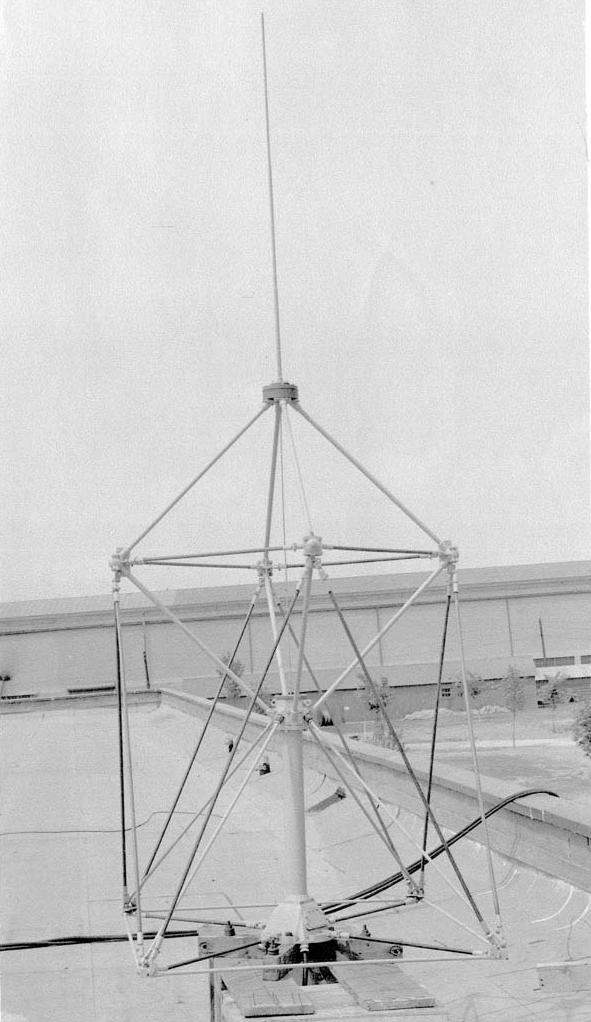 |
DAR antenna outfit mounted on the roof of a building. Click to enlarge. The antenna is very similar to frame coil S25B except that it does not have the test loop. (Likely a Naval Research Laboratory photo). |
 |
| Type 902 (2 inch) CRT. (Photo courtesy Sphere Research) |
Back to Ships Radio Equipment
Credits and Contributors:1) http://www.rnmuseumradarandcommunications2006.org.uk/B35%20RECEIVER.htm
2) Robert Downs <WA5CAB(at)cs.com>
3) Will <W0EOM(at)aol.com>
4) Sphere Research http://www.sphere.bc.ca/test/crts.html
5) http://rnmuseumradarandcommunications2006.org.uk/DF%20Outfits%20Late%201920%20to%20Early%201950.pdf
6) http://rnmuseumradarandcommunications2006.org.uk/RECEIVER%20B21B%20WITH%20FH3.pdf
7) Library and Archives Canada file "HMCS HAIDA File Number 7400-DDE-215V1"
Derc 20/20