Frequency Range: 1 to 25 MHz
Manufacturer: Plessey
Some notes about the FH-4 are provided by John Wise:
In the RN, outfit FH4 was being used ashore in 1943 and did not get
accepted for shipborne use until later.
According to the FH4 handbook BR 1569, the system had five RF ranges:
1 to 2, 2 to 4, 4 to 8, 8 to 16 and 16 to 25 MHz with an actual RF coverage
of 0.96 to 25.5 MHz, hence five sets of plug-in coils for the early sets.
There were three IF stages all running at 450 KHz, although not stated,
there is an equation which suggests that the low frequency oscillator tracks
high. So if the RF was turned to 5 MHz then the LO would have been at 5.450
MHz. The test oscillator also operated at 450 KHz, so it would not directly
interfere with any RF signal but it would be immediately accepted by the
IF stages, regardless of the tuned frequency. An elegant solution.
According to BR 1569, the system is designated FH4, the 4th High Frequency
DF system using a B-T frame coil antenna. The individual components of
which are the receiver - FHB (APW 6142 - without gyro, APW 6142A - with
a gyro), the Power Supply Unit - PSU for FHB (APW 6143), the Voltage Regulator
(APW 5981) and the Frame Coil - S25B (AP W6118A).
AP = Admiralty Pattern, and subject to confirmation, W = Wireless, a
designator which was dropped by 1950.
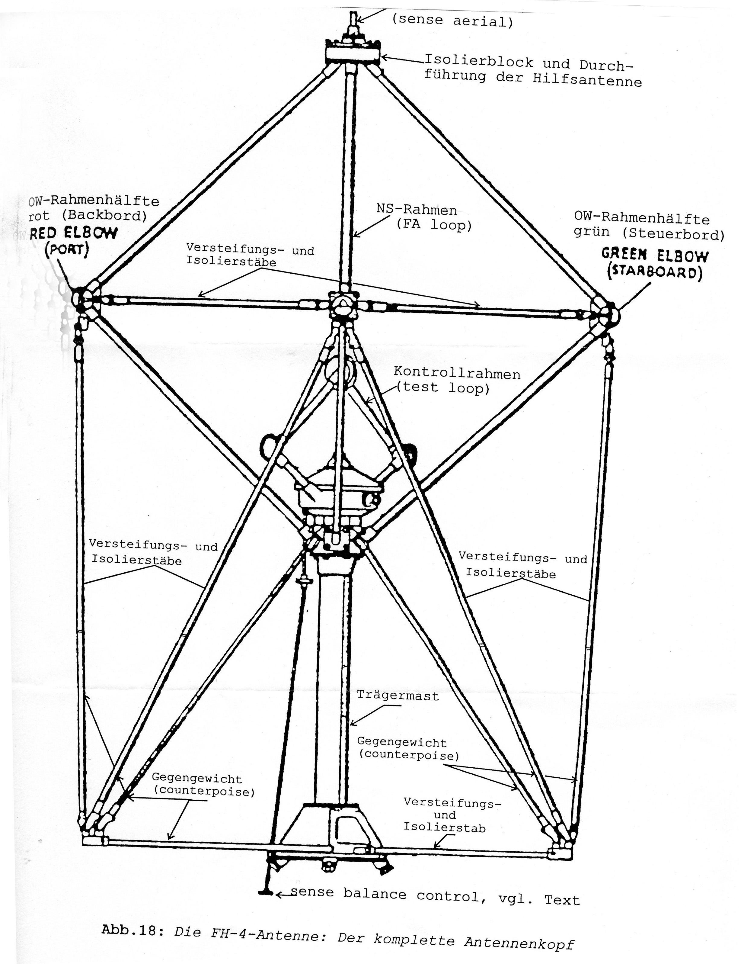
It appears that at least four aerials were associated with the FH-3
and FH-4 HF DF systems. They are designated S16, S18, S25 and S25B. The
only difference between the S16 and S18 is their size. The S16 was crossed
diamonds with a 3 foot aperture, usually fitted on top of a pole structure.
S18 had a 4.5 foot aperture and was often integrated into a mast structure.
The S16 had a short 'spike' on top - this was not a sense aerial but a
lightning conductor. S16 was used on corvettes, frigates, destroyers
while S18 was fitted to cruisers, carriers, battleships and depot ships.
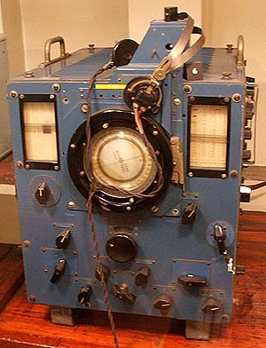
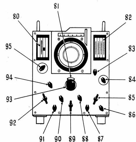
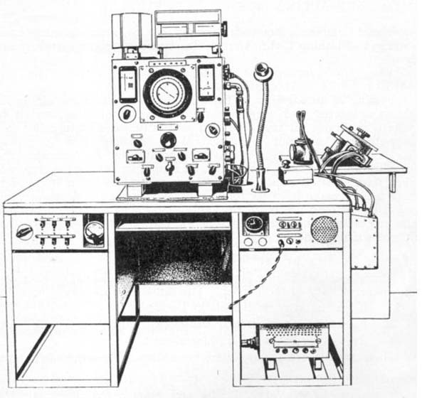
The FH4 had a cathode ray scope for diametric visual bearing indication
and was superior to its predecessor due to the ability of being able to
visually distinguish between the sky wave and the ground wave from the
lissajous figures on the CRT. Its scope was as big as a pie plate, and
was surrounded by a compass rose. Accuracy was variable from 2 degrees
plus, dependent upon emitters range and the prevailing propagation. The
unit was powered by a 230 VAC 50 Hz mains source with a voltage stabiliser.
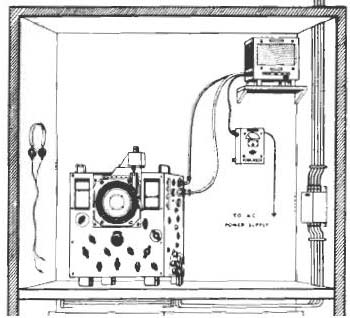
The FH4 was connected to a Bellini-Tosi aerial array consisting of fore/aft
(F/A), port/starboard (P/S) loops and a vertical sense aerial. The initial
sets were designed with five aerial/RF coils that had to be changed for
different frequency ranges. In 1944, the set was improved by the
addition of a pair of band changing switches, one each for aerial coil
and RF coil selection. The twin channels shared a single intermediate frequency
unit, which saved a significant amount of channel balancing in gain and
phase.
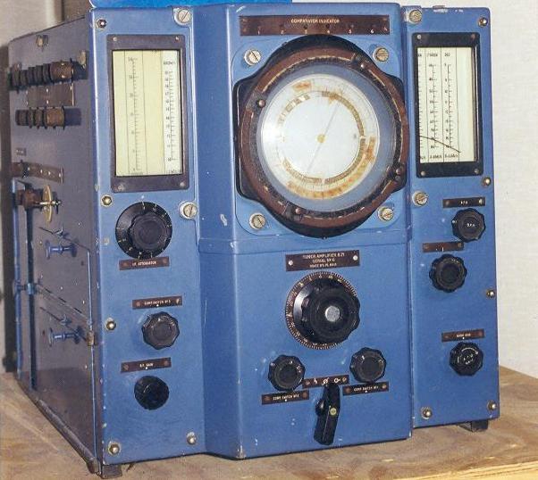
VARIANTS
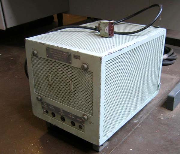
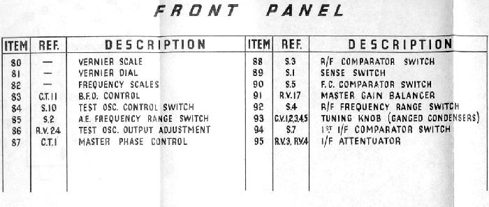
So far, three FH-4 variants have been identified. The FH-4 type 1 has
a raised front panel (see B71 photo) without the two band changing switches.
The second version, FH-4 type 2 has a flat front panel and no band
changing switches. Neither the Type 1 or Type 2 originally had a coupled
gyro repeater. This only came with the introduction of the Type 3 in early
1944. However, to overcome a serious lack of material shortages around
that time (Collingwood Archives, ASE Bulletin RH600(1) March 1944, page
37), a modification kit to give the FH4 Type 2 a gyro was introduced.
Type 3 Variant has a flat front panel with two band changing switches
(switched coils). These had to be switched in unison to ensure that the
antenna and RF selections were the same for a given frequency band. Type
3 was a significant improvement in having both a gyro and aerial and RF
band switching.
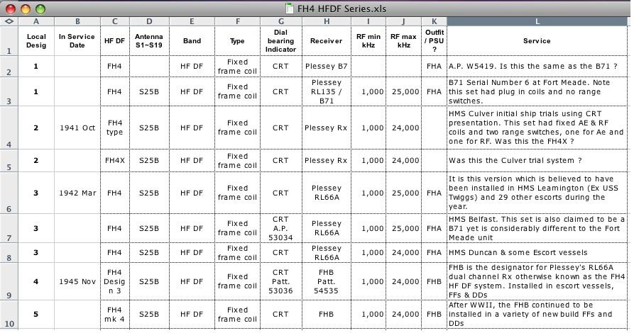
John Wise has compiled a summary listing of the FH4 DF variants in a
JPG spreadsheet which can be viewed here.
John is looking for pictures of some of these variants in order to confirm
the findings and also to identify any APW, AP or simple Admiralty Pattern
numbers that are appended to each type.
A word about Plessey, the manufacturer of the FH-4, from John
Wise:
The FH4 series was developed and built by Plessey at their Ilford Plant
in the outer east end of London during WWII. The Germans knew about this
production plant and bombed it quite early in the war. As a result of repeated
bombings, the government was approached with a request to consider moving
production underground.
At that stage, a new Central Line underground railway extension line
was being constructed out towards the far east end of London and its eastern
suburbs. The tunnel had been built but the rails had not been laid in and
there were no plans to complete the work during WWII. Instead, approval
was given for Plessey to move its production into 5 miles of the
tunnel system.
A brief contact with an ex-Plessey employee told me that Plessey management
apparently became very touchy about the possibility of the Germans over-running
the UK and considered that London might be their first objective. The result
was that Plessey destroyed all development system paperwork and soon as
an equipment went to production, and then destroyed production records
as each product run completed. yet!
We may never actually find any solid information about the RL 135 receiver
and whether it was a single or dual channel system sharing a single local
oscillator like the RL66. (FH4). This information came from a single telephone
conversation with an elderly ex-Plessey contact who I had hoped to meet
but sadly he died a short time after our conversation.
During WWII, Plessey Ilford employed 11,000 personnel and by 1946 that
number had dropped to just 6,000 because it lost so many military contracts
at the end of the war. As a company, Plessey no longer exists.