AN/GRD-6 HFDF System
Frequency range 2 to 32 MHz
The AN/GRD-6 Direction Finding system automatically furnishes
azimuth [1] indications within the frequency range of 2 to 32 MHz for targets
of interest. Coverage is split into two parts. One antenna array coves
the low portion of the HF band from 2 to 8 MHz while another array covers
the high portion of the HF range from 8 to 32 MHz. The system is comprised
of two antenna arrays, a radio receiver and a bearing indicator. Antenna
elements forming the low HF group are terminated, folded, monopoles forming
a U-Adcock configuration of four pairs of monopoles, equally spaced
to form a circle. High band HF antennas are broadband sleeve or cage type
antennas. Low band elements are 27 feet long and are spaced around the
circumference of a circle 100 feet in diameter. The high band elements
are 15 feet long, and the circle they form is 25 feet in diameter. In the
centre of each circle is a sense antenna.
Buried 2 to 4 inches under each antenna array is a circular mat constructed
of copper wire mesh. The low band mat is 300 feet in diameter, the high
band mat 100 feet. As can be seen by comparing figures, the ground mat
extends well outside the arrays. This ground mat reduces polarization error
and provides a stable ground system allowing consistent and reliable direction
finding performance, independent of local ground conductivity.
The R665 receiver used in the system covers the entire frequency range
in four bands: 2 to 4 MHz; 4 to 8 MHz; 8 to 16 MHz and 16 to 32 MHz.
Two receiving groups are used with the AN/GRD-6, one for the low band
and the other for the high band. Each performs similar operations for its
corresponding frequency band and is almost identical in function and physical
appearance. Each receiving group consists of several units but the operator
will be concerned primarily with the superheterodyne receivers. The receiver
converts RF signals from the antenna array to suitable deflection current
for display on the indicator cathode ray tube. In addition to the deflection
current output for the indicator, the receiver also supplies audio output
which may be applied to a loudspeaker or headset.
Both the high and low band indicator groups are composed of an azimuth
indicator and an indicator control. The prime function of this group is
to provide a visual DF display to the operator on the face of the cathode
ray tube to indicate the direction of arrival of an incoming signal.
Additional details on the operation of the AN/GRD-6 can be found in
NAVSHIPS
10232-A (Communications Technician M 3 & 2) Included are
functional and overall block diagrams of the system. Note that this is
not a GRD-6 technical manual but an extract from Chapter 18 regarding direction
finding techniques using the GRD-6 as an example.
 |
| Developed in 1958 by the US Naval Research Labratory (NRL), the highly
classified AN/GRD-6 system was comprised of two arrays and associated
electronics. The high HF array, depicted here, consisted of eight monopole
sleeve antennas and eight, terminated, folded monopoles for
the Low HF band, arranged in two separate circles. In the middle of each
circle was a sense antenna.
The arrays could also be installed in two concentric rings if space
was a premium. Such was the case for Canadian Forces Station Bermuda, where
guyed, rod antennas were used. The concentric ring configuration
was staged and tested by the United States Navy at Winter Harbor, Maine.
The monopoles were also known as "self-sustaining broadband
sleeve antennas". This design greatly reduced the octangular [2] error
of the GRD-6 set. (NRL photo #37851) |
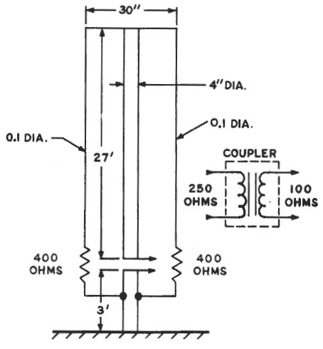 |
| This is a schematic of the terminated, folded monopole antenna which
comprises the low HF array. Note the mast diameter of 4 inches. (Drawing
courtesy USN) |
AZIMUTH INDICATOR
The IP-272 azimuth display consists of a CRT using magnetic deflection.
Its sweep speed is synchronized with the goniometer rotor speed. Deflection
is adjusted in such a manner that for no signal condition the spot is travelling
around the edge of the CRT. When the signal is maximum, the spot is at
the centre of the screen. With this arrangement, the familiar propellor
pattern develops from the Adcock antenna system.
 |
| IP-272 azimuth indicator controls. (Image
courtesy USN) |
TELETYPEWRITER CODER
Bearing data observed by the operator on the CRT is translated into
teletype code and automatically transmitted to recording equipment by the
Bearing Coder group. The text calls it a Bearing Coder but the device in
the equipment photo is labelled Teletypewriter Coder. The KY-168 is not
a cryptographic device since it lacks the TSEC (suffix) designator in the
model number. Bearing data can only be sent after the operator has
determined the sense of the signal . Pushing the quality pushbutton determines
strength and readability of the signal then launches some other events
which cause the bearing to be read, coded and sent over the teletype circuit.
Additional detail on this operation is found in the NAVSHIPS 10232 manual.
EQUIPMENT OPERATION
Any signal within the receiver's frequency range received by the antenna
system causes a bearing pattern to appear on the indicator screen. The
alidade [3] ring on the indicator is then rotated by the operator
until the arrowheaded cursor line bisects the tips of the propeller pattern
illuminated on the face of the cathode ray tube. The direction of the pattern
is next determined by depressing the sense switch on the indicator panel
This operation replaces the propeller pattern with a cardioid [4] pattern.
Figure 12-4A illustrates the propeller pattern and 12-4B the cardioid pattern.
 |
| Figure 12-4A top and 12-4B bottom. (Image courtesy
USN) |
If the cardioid or sense pattern is in the direction of the
tail of the arrow (leaving the arrowhead clear), the bearing is direct;
if the sense pattern is in the direction of the arrowhead, the bearing
is a reciprocal. The appropriate pushbutton on the switch box is then depressed.
If the sense of the bearing cannot be determined, the "no sense" pushbutton
on the switch box is depressed. The indicator lamp lights after its respective
pushbutton has been depressed. One of the quality indicator pushbuttons
is next depressed, depending on the quality of the bearing to be transmitted.
If a bearing pattern is not present on the indicator screen when attempting
to obtain a bearing, the "no bearing" pushbutton is depressed. Figure 12-5
shows the location of the various pushbuttons and controls on the switch
box.
 |
| Figure 12-5. Switch Box SA-430 controls (Image courtesy
USN) |
The need for accurate bearings cannot be overemphasized. One
negligent or careless operator can sabotage the efficiency of the entire
HFDF net. The equipment itself has certain features which, if used conscientiously,
will help eliminate operator error. One example of this is the arrow etched
on either side of the alidade, which, if used properly (as you would use
the sights of a rifle) will eliminate parallax. Another feature, although
not part of the original AN/GRD-6, is the azimuth mask. The mask is inserted
between the alidade and the amber light filter on the indicator and is
etched showing the spread of bearings for each classification of bearing,
thus providing an aid to the operator in classifying his bearings. With
practice, accurate bearings may be obtained without using the azimuth mask,
but remember, accurate and objective bearings and bearing classifications
are always desired.
 |
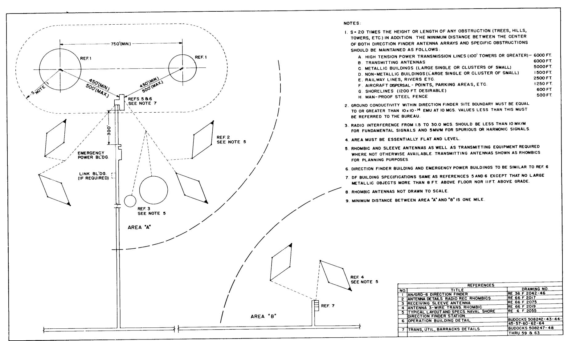
This is the antenna plot plan for the AN/GRD-6
system. Click on image to enlarge. This plan also takes into account, the
placement of transmitting/receiving antennas for internal communications
between HFDF sites when a direct landline is not available.
(Diagram courtesy USN) |
FOOTNOTES
[1] The terms azimuth and bearing are used interchangeably
throughout this document. USN DF manuals specifically define Bearing as
degrees clockwise from true North. (and relative bearing from own ship
heading). This is also true for many USN manuals. For example a paragraph
headed "Bearing Indicating Equipment" says "...azimuth indicator and indicator
control". Another says - "...the two bearings are 180 degrees apart in
azimuth".
[2] Octangular - [ok-tang-gyuh-ler] having eight angles
[3] Alidade - [al-i-deyd] is a straightedge having a telescopic
sight or other means of sighting parallel to the straightedge.
[4] Cardioid - [kahr-dee-oid] resembles heart-shaped curve, being
the path of a point on a circle that rolls externally, without slipping,
on another equal circle.
QUESTIONS:
If you can answer any of these questions, please contact: jerry.proc@sympatico.ca
1) What is the purpose and usage of the C-1647/GRD-6 Receiving Group
Control?.
2) Apparently there is a technical film report which describes the installation
of a model AN/GRD-6 DF Central. It shows the preparation of the site, installation
of the low-band and high- band antenna arrays, and the handling of cables
along with accuracy of plans and installation. Does anyone know how to
get access to a copy of this film?
References and Contributors:
1) GRD-6 antenna array photo submitted by Will, W0EOM
<W0EOM(at)aol.com>. Source book is titled "Evolution of Naval
Radio-Electronics and Contributions of the Naval Research Labratory. NRL
Report 7300 by Louis Gebhard. (1979)".
2) Naval Security Group site
http://www.navycthistory.com/skaggsisland_introduction.html
3) Bill Robinson <newman-robinson(at)rogers.com>
4) Terceira Island http://www.navycthistory.com/images/azores19_2.jpg
5) Nick England <navy.radio(at)gmail.com>
http://www.navy-radio.com/grd6.htm
6) 1964 USN manual .
7) Bearing vs Azimuth http://answers.yahoo.com/question/index?qid=20080614075648AAL4K1X
This is a multi entry document. Use Browser's back arrow to return
to previous document.
Oct 9/13