 |
 |
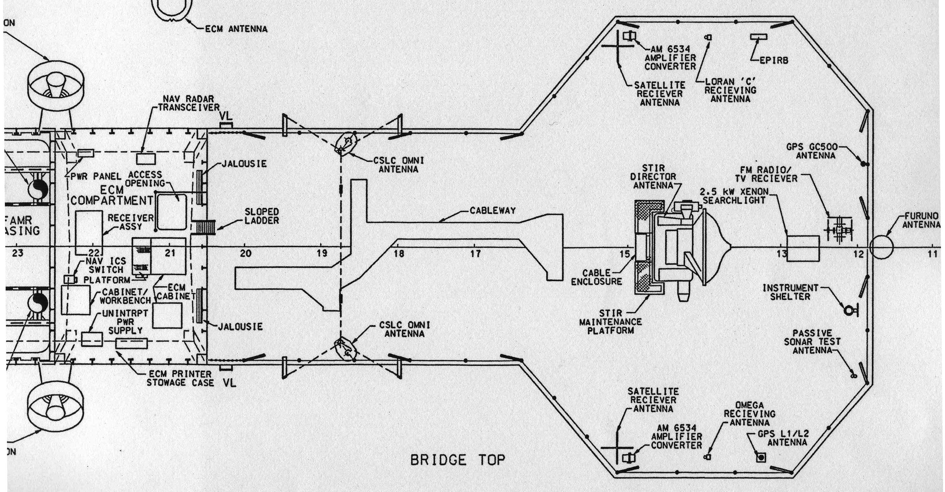 |
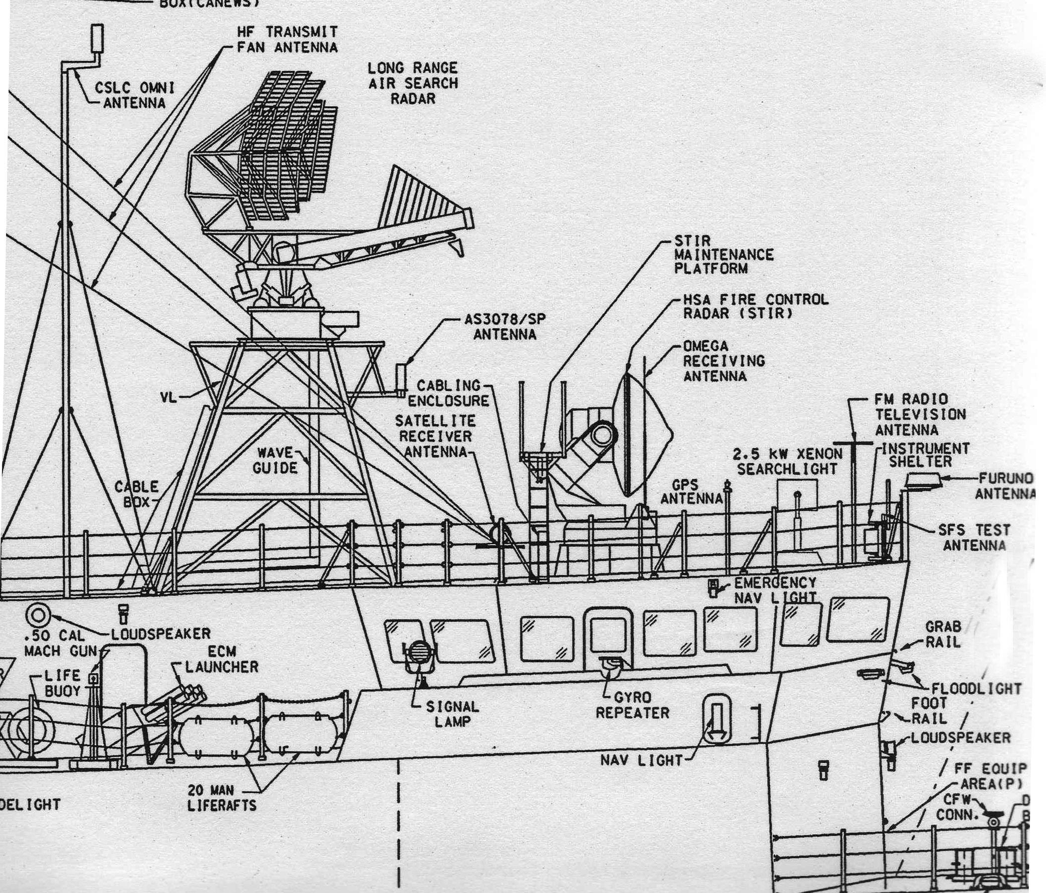
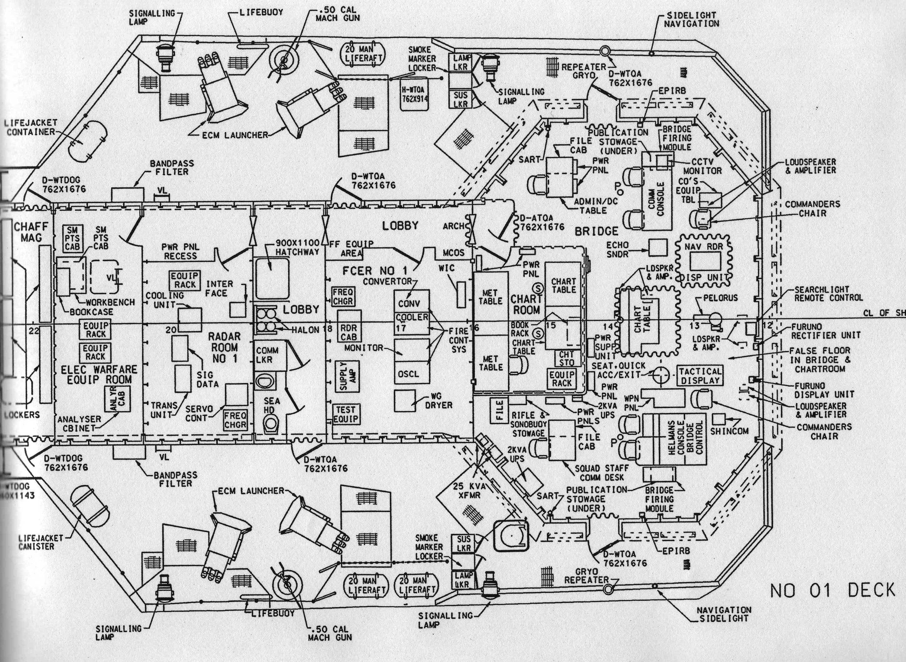
| Bridge Profile | Bridge Layout | Bridge Top |
 |
 |
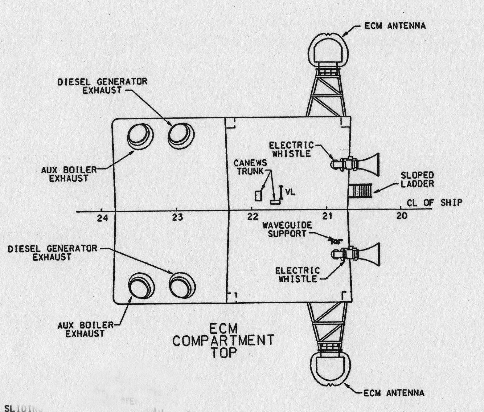 |
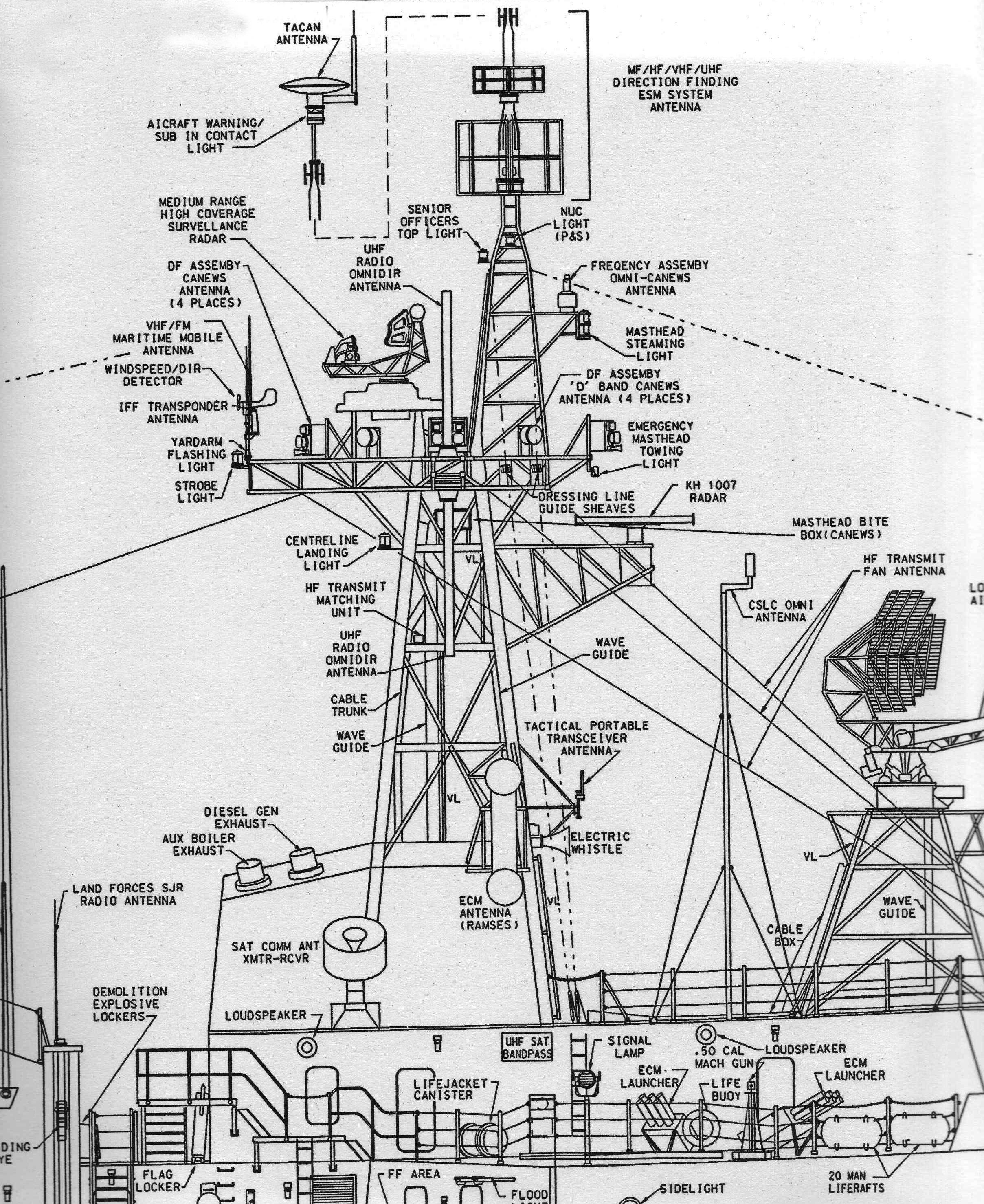
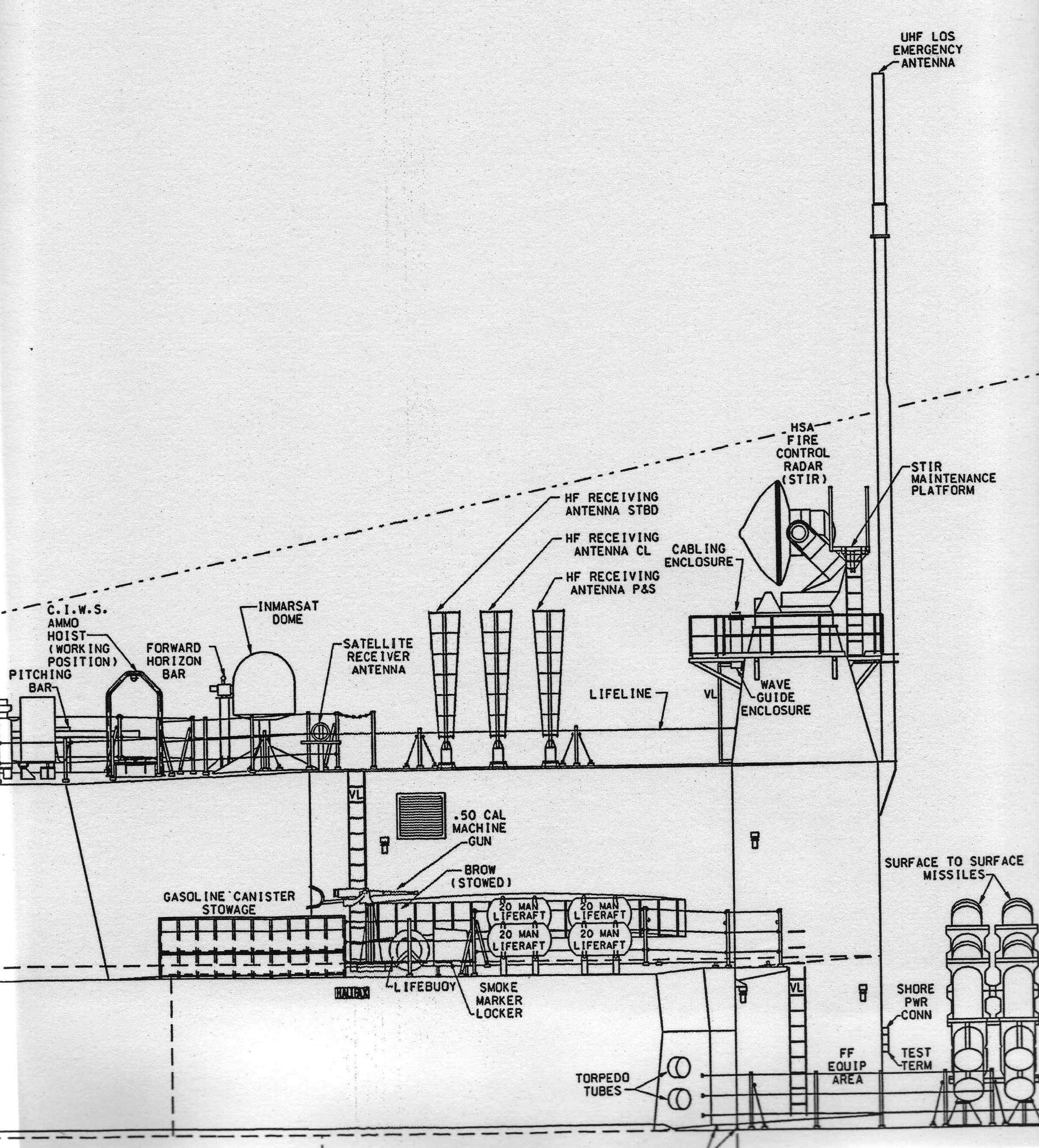
| Communications | Foremast Profile | Top of ECM |
 |
 |
 |
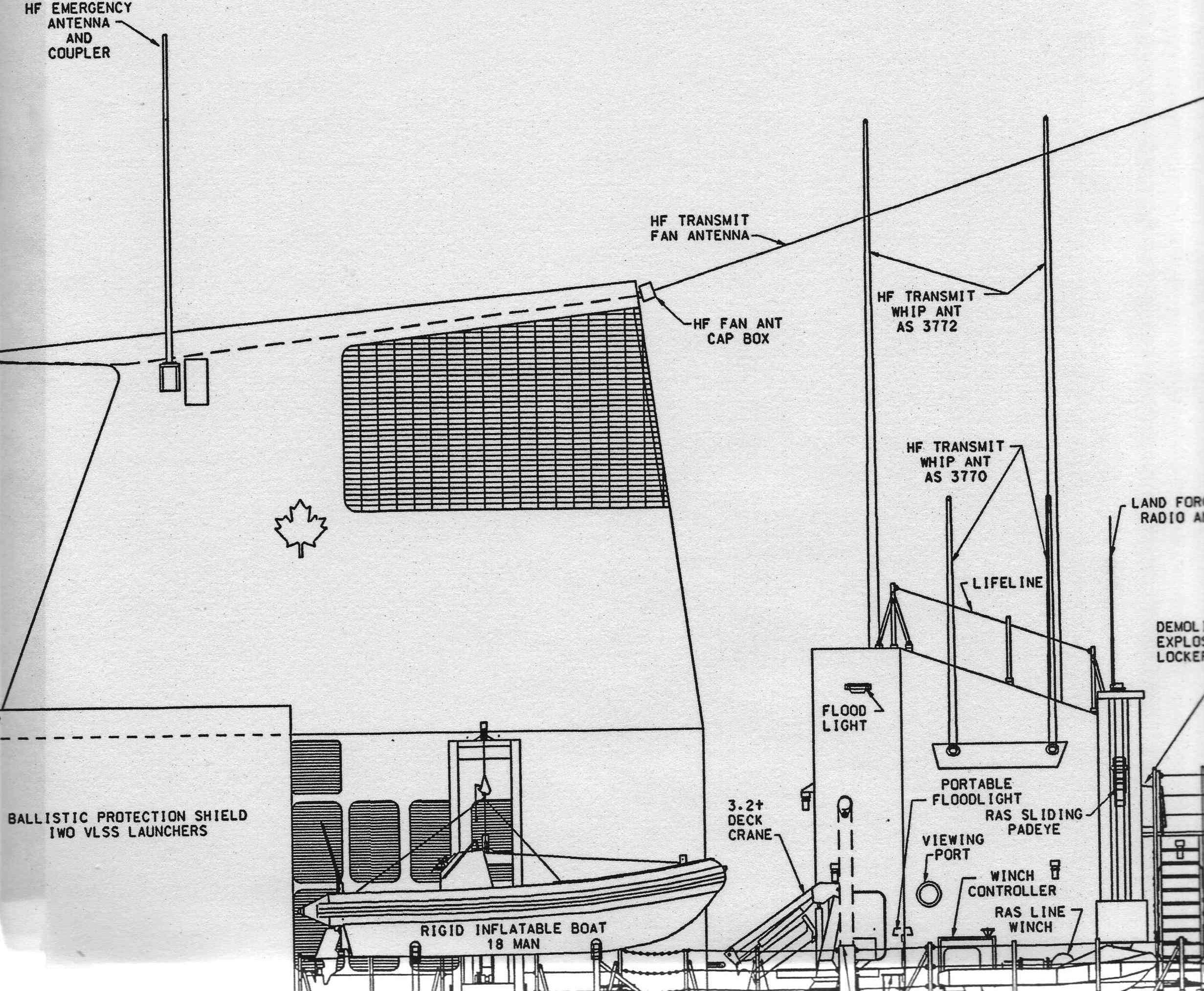
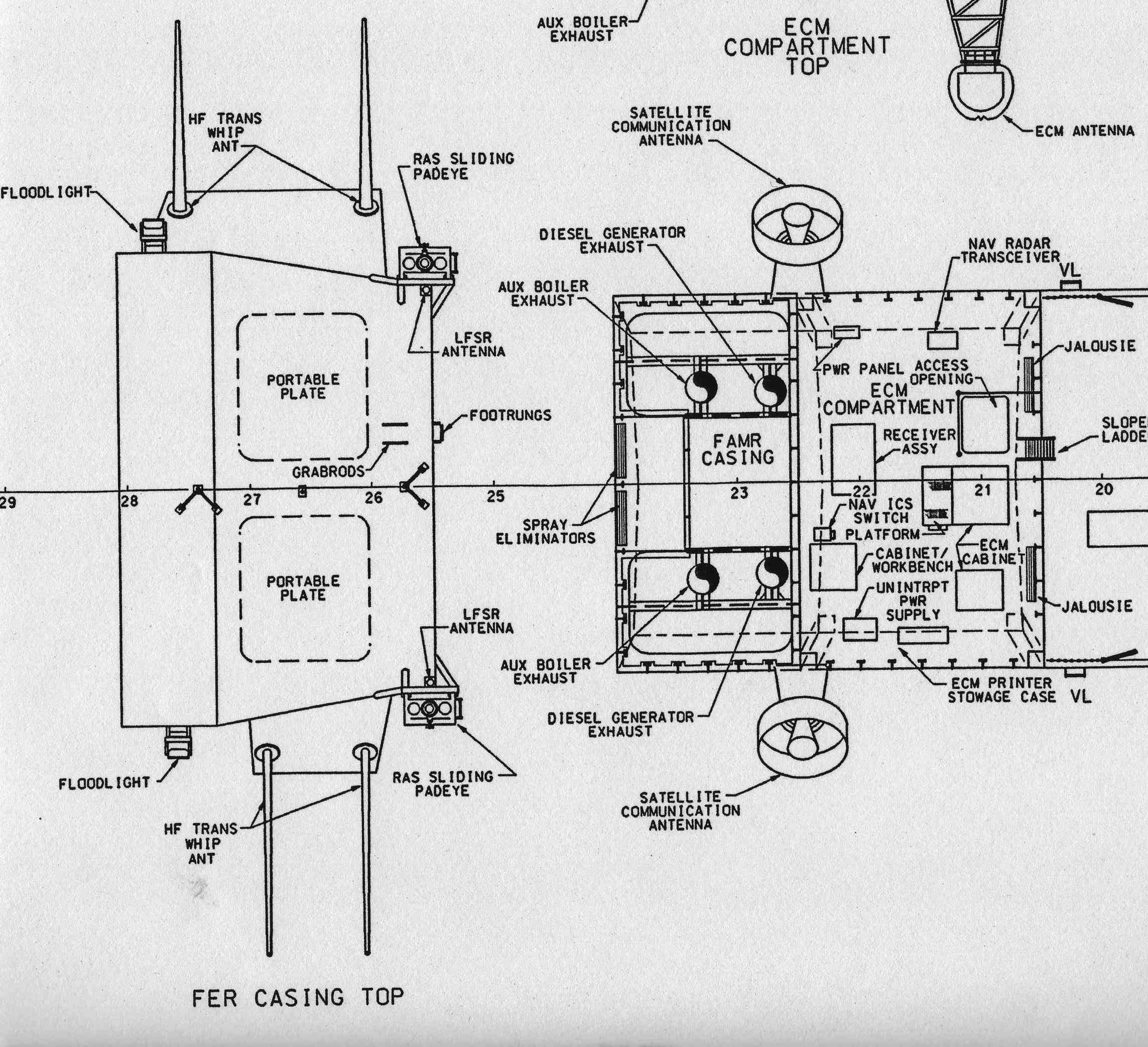
| Stack Profile | Inlet Top | Hanger Profile |
 |
 |
|
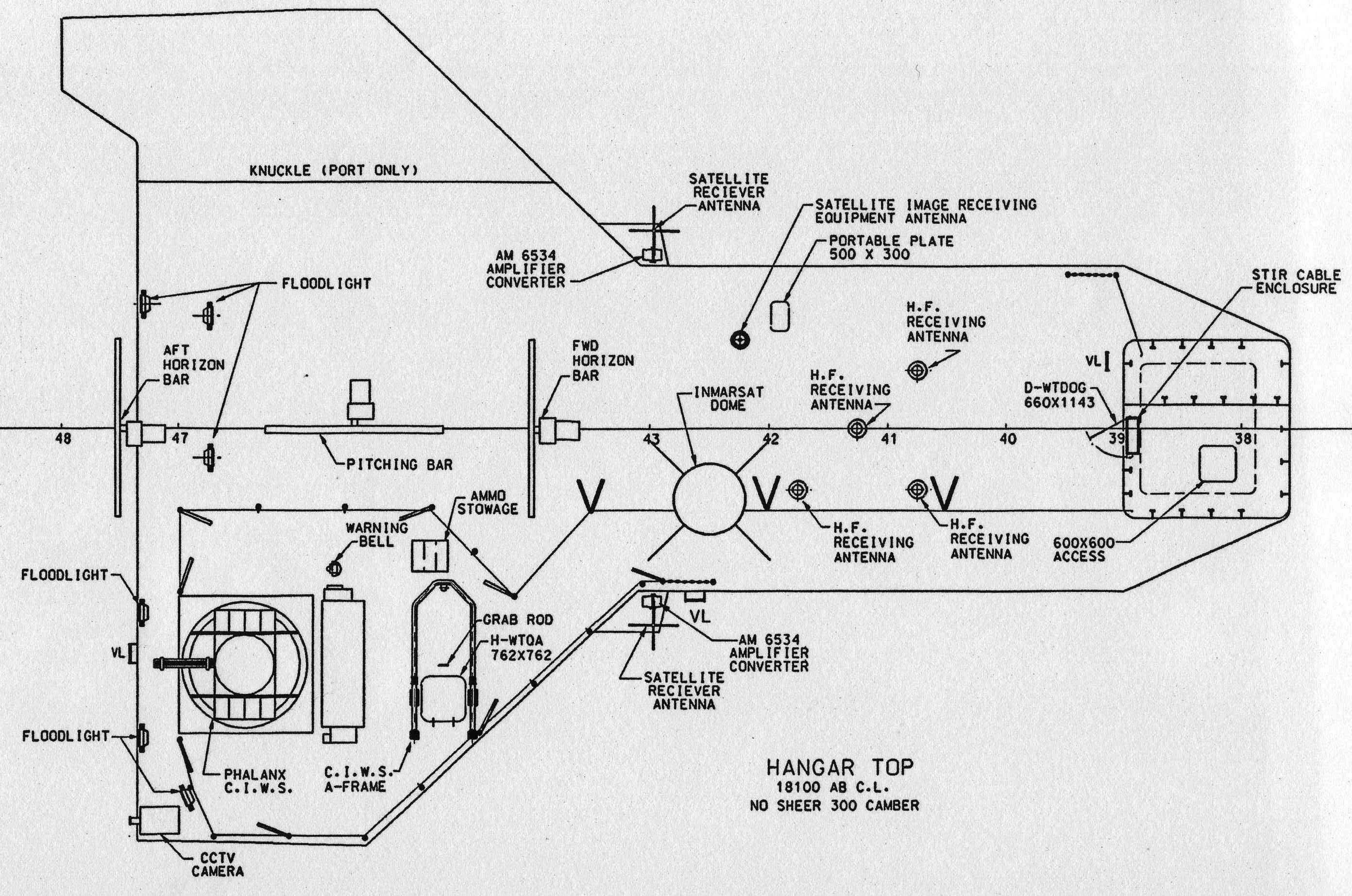
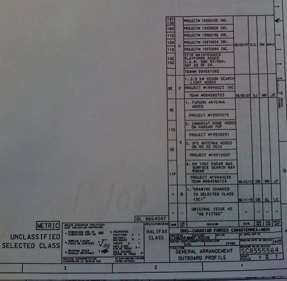
| Hanger Top | Legend For As-Built Plans |
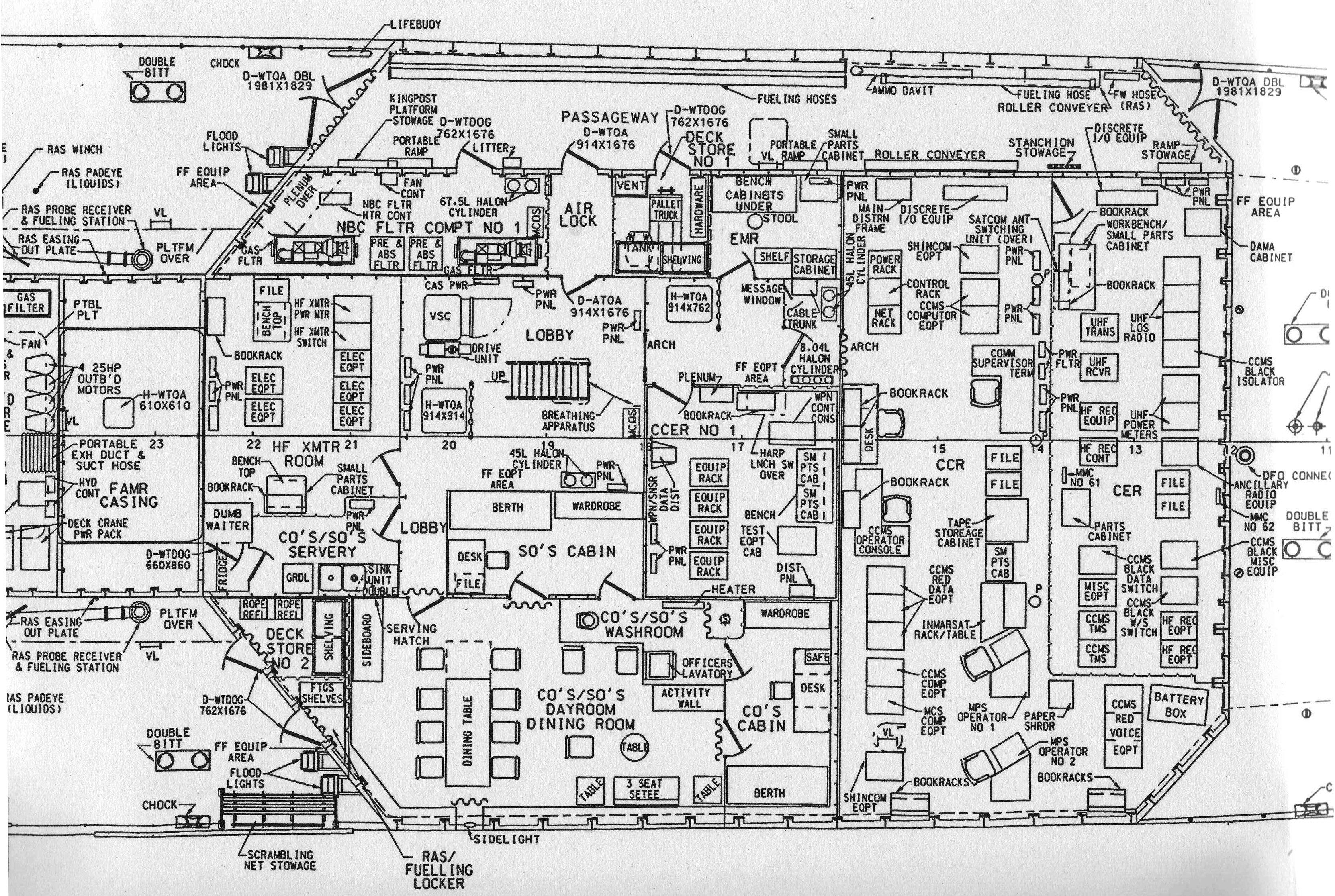
The images below, which feature the Halifax class external features, were provided by Nick Strauss. Also included is the layout of the communications area. In the legend image, the dates range from 1996 to 2000. Click on any image to enlarge.
|
|
|
| Bridge Profile | Bridge Layout | Bridge Top |
|
|
|
| Communications | Foremast Profile | Top of ECM |
|
|
|
| Stack Profile | Inlet Top | Hanger Profile |
|
|
|
| Hanger Top | Legend For As-Built Plans |
WHIP ANTENNASSo why are the whip antennas mounted at a slight angle aboard a 330 class frigate?\
ChatGPT provides some reasons.
Whip antennas aboard an RCN 330-class ship are mounted at a slight angle for several reasons:1) Minimizing Interference Angling the antennas reduces the risk of signal interference from other nearby antennas, structures, or electronic systems on the ship.
2) Operational Clearances The tilt ensures they dont interfere with flight operations on the helicopter deck or with other shipboard equipment.
3) Radiation Pattern Optimization Angling can help optimize the radiation pattern for better radio wave propagation, especially in shipboard environments where reflections from the water and metal surfaces can affect communications.
4) Structural Considerations The angle may help distribute mechanical stress on the antenna base, particularly in high winds or heavy seas.
5) Standard Naval Design Many modern naval vessels use similar mounting angles to ensure effective communication while maintaining a sleek and functional deck layout.
Credits and References:1) Nick Strauss <strauss.nick(at)gmail.com>
March 27/25