EQUIPMENT DESCRIPTION FOR 1957
AN/SCG-1 A radioteletype terminal set. See
description in 1962 section.
CSR5A receiver. See description in 1962 section.
FSC107 Frequency Shift Converter. See description in 1962 section.
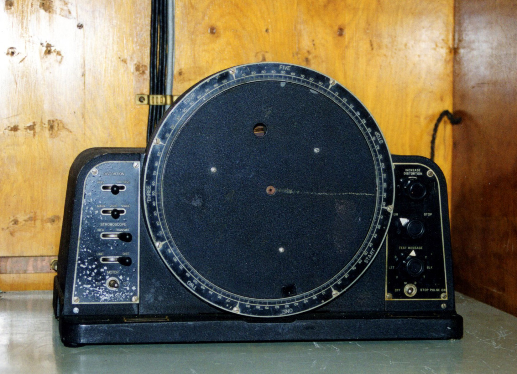
Model SFO Teletype Regenerator.
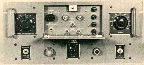 |
| Model SFO teletype regenerator. The front panel
door in the down position. (Photo courtesy TMC) |
According to BRCN 5422 , bias distortion is the lengthening of the mark
or space signal at the expense of the other. For an acceptable minimum
amount of errors, the teletype signal must not have more than 5% bias distortion.
There are three sources that contribute to distortion - mechanical, electrical
and propagation., however BRCN 5422 dwells on the discriminator circuits
in the Frequency Shift Converter as being problematic.
To correct bias distortion, a regenerator was placed between the Frequency
Shift Converter and the teletype machine. The SFO is capable of accepting
teletype signals in audio (on-off) form or in direct current form (polar
and neutral) and having up to 45% bias distortion. When regenerated, the
output signal will have less than 5% distortion. Made by Technical Material
Corp.
SPECS
* Accepts 60, 75 and 100 wpm teletype signals.
* Input keying - 500 to 3 KHz tone, 30 ma polar, 60 ma neutral, simplex
or diplex
* Power input: 105 to 125 VAC, 50 to 60 Hz; 85 watts.
Once encrypted broadcast was introduced in 1962, the SFO
was no longer needed as the regeneration of a teletype signal was handled
by the KWR-37 crypto receiver.
SUMMARY OF FUNCTIONS circa 1962.
Radioteletype (abbreviated as RATT in the RCN) was already installed
in HMCS Buckingham in 1954 as recalled by Radio Op Denies Stapleton.
Over the next few years broadcasts were sent over the RATT circuit
along with the normal CW broadcast until all designated ships had RATT
capability and the system proven reliable.
Sitting on the table is the Model 14 Reperforator which allows
an operator to create a punched paper tape with a message on it.
This tape would then be mounted unto the Model 14TD (Transmitter- Distributor
aka tape reader) where it awaited transmission. Once the operator started
the tape reader, an electrical signal (Baudot code) was sent to Radio 2
via hardwired cable, That signal was then converted into RATT form by a
Frequency Shift Keyer which in turn keyed the 500 watt PV500 transmitter.
RATT broadcasts could also be copied on LF or HF and printed on
one of the two teleprinters. It was a case of copying one broadcast or
the other but not both. A thick, black jacketed cable permitted the
selection of either the LF or HF receiver output to the input of the Frequency
Shift Converter. Encrypted broadcasts were automatically decoded
by the KWR-37 on-line crypto receiver. Two of these were situated in racks
on the starboard side of the Message Centre. Unfortunately, examples
of the KWR-37 are unobtainable at this time,
Mounted on the port bulkhead of the Message Centre is the TT-23 Teletype
Distribution panel. Using patch cords terminated with male telephone jacks,
this facility permitted the radio ops to reconfigure the interconnection
of RATT equipment within the Message Centre to suit operational needs.
| 1.2.1 - AN/SGC1A Radioteletype Terminal Set
 VHF and UHF radioteletype was used for short range fleet broadcasts in
the 225 to 400 MHz UHF band. It was very likely that the escort force commander
would want to have a UHF RATT circuit dedicated for his use with his screening
ships in addition to a tactical, UHF voice circuit. One contributor suggests
that RATT over UHF could have been used in harbour to relay broadcast messages
between the Command Message Centre and ships in port. Can anyone confirm?
(Photo
by Jerry Proc)
VHF and UHF radioteletype was used for short range fleet broadcasts in
the 225 to 400 MHz UHF band. It was very likely that the escort force commander
would want to have a UHF RATT circuit dedicated for his use with his screening
ships in addition to a tactical, UHF voice circuit. One contributor suggests
that RATT over UHF could have been used in harbour to relay broadcast messages
between the Command Message Centre and ships in port. Can anyone confirm?
(Photo
by Jerry Proc)
Also, was there any off-line encryption applied to these RATT over UHF
messages? Contact jerry.proc@sympatico.ca .
When a RATT message was to be transmitted, the teletype machine or paper
tape reader (T-D) would interrupt a DC current loop based on the elements
of the Baudot signalling code. The resulting pulses were applied to the
input of an audio oscillator within the terminal set. These pulses then
keyed the oscillator to produce either a 500 Hz or 700 Hz audio tone. When
the loop was closed a 700 Hz tone was produced. A 500 Hz tone was produced
when the loop was open. The 700 Hz tone was considered to be the MARK state
while the 500 Hertz tone was the SPACE state. Alternately opening and closing
the loop caused the output of the terminal set to toggle between 700 and
500 Hz, thus representing the Baudot code as a warbling audio tone. In
turn, the audio output was applied to the microphone input of an AM transmitter.
This method of keying the transmitter was called Audio Frequency Shift
Keying (AFSK) or "tone modulation" in its heyday.
When traffic was to be sent, a control signal from the SGC1A placed
the radio transmitter on the air until the messages had been transmitted.
This control signal was activated by striking the space bar on the Teletype
machine prior to sending traffic. Alternately, if the T-D was used was
the input source, the first character on the tape would have to be a space
character.
When receiving messages, the process was reversed. The SGC1A accepted
the incoming mark and space tones from an associated AM receiver such as
the AN/URR35A. These toggling tones ultimately controlled the keying of
the DC current loop. This terminal set was manufactured by the Remler Co.
Ltd. of San Francisco. The first examples of the AN/SGC1A were produced
in November of 1950. |
CSR5 Receiver
The sole purpose of this receiver was to receive high frequency RATT
signals which provided input to the frequency shift converter. Normally,
reception was crystal controlled, however, when crystals were not available,
the CSR5 tuning control had to constantly be readjusted to maintain proper
RATT reception. When CSR5 receivers were rack mounted, they were usually
powered with a Marconi WE11 rack mounted power supply. This supply only
operated from a 120 or 220 VAC power source. On HAIDA, a replica was constructed
to replace the WE-11 unit that was missing.
KWR-37 On-Line Crypto Receiver
 |
| Code named JASON, the sole purpose of this unit was to automatically
decipher the encoded RATT fleet broadcasts. On the input side, it was connected
to the current loop output of a frequency shift converter. The output side
was connected to a Teletype. (Photo courtesy NSA) |

|
|
The interconnection of the KWR-37 to the radio equipment.
|
GENERAL INFORMATION
The shore station started each day's broadcast at 0000 Zulu and transmitted
without interruption for 23 hours and 55 minutes each day. On shore, the
encryption device such as a KWT-37 was synchronized with a time signal
station (CHU or WWV) and the originating device sent an automatic 'start'
signal followed by a continuous stream of encrypted, non-repeating traffic
throughout the day.
The decoding 'key' which was similar to an IBM style punch card had
a pattern of randomly punched holes, and had to be changed daily, prior
to the start of the next day's broadcast. Encryption keys were changed
by unlocking a front door on the KWR-37, removing the existing card, and
installing the card that was designated for the next day. These cards were
inserted behind a small door in the front of the KWR-37 using the built-in
alignment pins. The door closed against a block of small, spring-loaded
steel pins. Where a pin touched the paper card, no signal passed; where
a pin poked through a hole in the card and touched a silver-plated metallic
track, a circuit was made. Each card held enough keys to cover 14 years
of usage before the key repeated itself. For very confidential messages,
the fleet broadcasts consisted of encapsulated five character cypher groups
which had to be decoded manually on a KL7 crypto unit. An example of this
type of message would be the notification of death of a crew member's next-of-kin.
Sometimes, there were periods were no messages were being sent on the Fleet
broadcast and the Teletype would just sit there receiving null characters.
John Dill of Kingsville Texas, was a crypto machine mechanic in the
USN in the 1960's and 70's, and kindly documented his experiences with
the KWR-37. "The holes in the punched cards directed the key stream to
a series of bistable multivibrators (flip-flops) which were wired on thirteen
printed circuit boards located on the left side of the machine when one
opened the equipment drawer. All the flip-flops plugged into a motherboard
which was positioned horizontally. The active devices in these circuits
were sub-miniature, type 6088, wire lead, sharp cutoff pentodes made by
Raytheon or General Electric. These tubes were about 5/16 inch in diameter
and 1 1/4 inches long and anchored by metal clips on each circuit board.
The 6088 pentode was also known as type CK522AX. Depending on circuit design,
the 6088 could be driven to produce as much as 10.5 mw of power at the
high end or as little as 1.2 mw at the low end! One multivibrator stage
consisted of two 6088 pentodes for the flip-flop and one 6814 sub-miniature
triode amplifier, a vacuum tube originally designed for late generation
tube computers. All stages had to be perfectly balanced, hence the use
of resistors with 1% tolerance. Typically, the pentodes ran at 67.5 volts
B+ and the triodes at 100 volts. There were four flip-flops per board and
the entire unit contained approximately 500 tubes.
In addition to the operational key cards, there were also cards used
strictly for testing. Each card in the test deck, checked a different KWR-37
function. Two of the cards, produced a distinctive pattern of beeps to
indicate proper operation and the technician had to listen attentively.
Used, operational cards were destroyed on periodic basis with two people
witnessing their destruction, depending on the specific 'customer'. With
care, the test cards could last for years.
The door for the key card was equipped with a lock in order to prevent
anyone but authorized personnel from seeing the punch card. For security
reasons, the card door was made from very thick steel. Details about the
construction of this door are still classified since a similar arrangement
was used on some newer machines. Affixed to the door, was a small placard
with the letters NOF. This stood for 'Not for Observation by Foreign national'.
It was permissible for a foreign national to view the front of the machine,
but that same person would have to leave the premises if the front door
of the '37 was opened for any reason.
When the '37 was first designed, an 'order wire' mode was incorporated.
It was intended to pass plain text instructions to the distant station
in order to bring up the system in crypto mode. These instructions were
to be passed in the clear using code words. When the '37 went into service,
the order wire was actually disabled.
OPERATION
Transmissions began at 0000Z and continued without pause or repetition
for 23 hours, 55 minutes each day. Whether any messages were being sent
or not, the 'customers' KWR-37's were on-line, in sync and receiving the
transmitted key stream. In the event of a power loss or if the unit went
out of sync, the operator would have to initiate a restart. When the sending
station stopped transmitting, all receiving units worldwide would be prepared
to receive transmissions for the next day. If radio conditions were normal,
the transmitting station's Auto Start signal would automatically start
the machine. If Auto Start was missed due to atmospherics, the operator
had to late start the unit. This procedure is discussed further in the
text.
On the front panel of the unit, there was a control composed of two
concentric dials; the outer for hours and the inner one for minutes. Above
that, were three miniature switches marked Start, Reset and Sync. Two small,
orange lamps tagged Mark and Space flashed alternately in time with the
incoming signal. Re- synchronization of the KWR-37 required that the machine
be reset, then run it forward in time at high speed to catch up to, then
slightly pass, the transmitting station's key stream. The operator would
set the Hours/Minutes dials to the difference between 0000Z and the current
Zulu time. The Hours dial was marked in 1 hour increments up to 23. Similarly,
the Minutes dial was marked in 5 minute increments up to 55. The Reset
switch would then be pressed. This would reset the flip-flops in the Key
Generator and the Internal Clock and ensure that all these circuits started
up from a desired, known, pre-set value. Internally, the reset signal was
routed to the flip-flop stages through the Key Card, thus changing the
initial 'set' state of the Key Generator. Pressing the Start switch would
enable and start the clock which began to drive the flip-flop stages thus
producing the key stream. Activating the Sync switch would give approximately
15 seconds worth of high clock speed, akin to a fast forward function.
If for example, the KWR-37 had dropped off-line at 14 hours into the
broadcast day due to loss of ships mains power, and restoral took 15 minutes,
the operator would set 14 hours, 15 minutes on the dials and hit the Start
button. The machine would run in high speed for several minutes until the
clock had advanced the key stream 14 hours and 15 minutes, at which time
it would drop back down to normal speed and start searching for sync. This
process forced the KWR-37 in constantly comparing it's own internal timing
to that which was being sent on the broadcast. If a clock comparison was
unsuccessful, the clock would delete a pulse, effectively dropping it back
in time by a small amount. Each time this pulse deletion occurred, an audible
beep was sounded through a panel mounted speaker. As the beep rate slowed,
it told the operator that synchronization was approaching. After several
seconds of silence the Sync light would illuminate and the Teletype attached
to the '37 would start printing.
If the search for synchronization ran over several minutes duration,
the '37 would alarm again with a steady, irritating, much-hated tone from
the speaker along with the dreaded red Alarm light. Standard procedure
called for resetting the machine and trying again. Since no two KWR-37's
were exactly alike, the presence of the alarm did not mean that the machine
stopped searching for sync. The alarm simply meant that the allotted amount
of time had elapsed, during which, synchronization should have been attained.
In many cases, the '37 achieved sync with the alarm sounding and the SYNC
light on. At this moment, the operator would silence the speaker and everything
would run normally. This was the official procedure for achieving synchronization.
In practice, however, it was an entirely different world. An operator
would generally attempt the formal procedure. If this did not achieve results,
a whole series of 'homebrew' remedies could be applied. Among these miracle
cures for lack of sync were: a) Pounding the front panel briskly just prior
to pressing the START switch.
b) Opening the equipment drawer and hitting the tops of the circuit
boards with some hard object such as a mallet or cleaning brush.
c) Opening the front door; removing the key card and cleaning the conductive
tracks in the rear of the front door with a rubber eraser. This practice
removed the plated silver on the tracks and was frowned upon.
d) Cleaning the conductive tracks with Teletype paper or paper money.
Since Teletype paper contained trace amounts of oil to assist with lubrication,
this practice was highly discouraged.
e) Rapid and vigorous spinning of the time-delay dials, followed by
many shots on the RESET button.
f) Uttering foul, abusive language at the machine in order to let it
know who was in charge.
MAINTENANCE
The KWR-37 was very old, tired and well past it's design life in 1968
and did not improve with age. Many technicians only had a modicum of training
in the art of soldering. For the '37 family, this was a disaster as the
most frequently performed corrective maintenance involved the replacement
of wire lead vacuum tubes. One can only imagine the damage that was done
to the printed circuit boards after 20 years of mediocre maintenance.
To ensure the highest reliability, crypto mechanics tried to turn out
a machine capable of operating normally with only 1 volt of filament voltage
to all the 6088 pentodes. The standard setting was 1.25 volts and was indicated
by a front panel meter. Each pentode had a filament draw of 20 ma. If the
unit ran properly at a reduced filament voltage, that meant that the tubes
had strong emission and the unit would run reliably. As emission decreased,
the operator could increment the filament voltage to restore normal operation.
When the machine became unreliable at a setting of 1.25 volts, it was turned
back to the maintenance depot. Checking for operation at a reduced filament
voltage became known as margining. The 6814 triodes which used indirectly
heated 6.3 volt filaments were not margined.
Later and unofficially, an extender board was developed which allowed
individual circuit boards to be margined. Once each board ran reliably
at one volt filament voltage, the filament supply to the entire machine
was reduced. If it worked, it was considered ready for use. Testing each
board individually improved the quality of the troubleshooting process.
The majority of maintenance problems in the '37 originated in three areas
of the machine: the 'S' circuit cards, (the ones containing the key stream
flip-flops); the 'T' cards which combined the 'S' card outputs and the
'U' or alarm cards. Next, were the cards which allowed the '37 to run at
high speed. The modified card extender was invaluable in finding these
circuit faults and eventually won official approval. A maintenance bulletin
was circulated among all KWR-37 holders documenting the modified extender,
the construction details and stock numbers of the parts required".
John goes on to comment about his worst KWR-37 repair job." A technician
had the '37 drawer open for maintenance. Innocently, a brand new Ensign,
who was the Communications Officer noticed the activity and came over for
a look. He must have been having a hard time at sea because of the large
bottle of Maalox (stomach antacid) in his shirt pocket. As the Ensign leaned
over to peek at the '37, the bottle fell out and broke on the top edge
of the equipment drawer. Needless to say, the Maalox spilled throughout
the machine and a large blue flash ensued as the power supply shorted out.
Flames and smoke began issuing from the drawer. The tech had been sitting
on the deck in front of the '37 cross-legged with his legs underneath the
extended drawer. His burning trousers were quickly extinguished by the
remainder of the Maalox running out of the equipment. In his haste to escape,
the tech placed his full weight on the card rack and broke the motherboard
in several places. The '37 was eventually repaired but the cost to repair,
likely exceeded the value of the machine".
Mechanically, the '37 was about 22 inches wide, around 24 inches deep
and 8 to 9 inches high with a case finished in navy cabinet grey. It was
usually positioned on an equipment shelf. With a weight approaching 100
pounds, it was definitely a two man lift when it was being installed. All
cabling plugged into the back of the unit.
OPERATING THE KWR-37 IN THE RCN
In the RCN, there was one minor difference in the manner that the KWR-37
machines were operated. Gregory Mclean of Abbotsford BC details the difference
and explains some operating practices. "In the RCN, the crypto cards were
not destroyed daily. At the end of each month, when we had finished with
that months pack, we returned them to the C.B. Officer (Confidential Book
Officer). To ensure separation of duties, the CBO was not involved in communications.
He was usually a junior officer with a number of unrelated duties. It was
up to him to destroy used crypto and other classified materials at predetermined
times. Sometimes, he requested help from communications branch personnel.
On smaller ships, the CBO could be the Communications Officer.
The KWR-37's went out of sync frequently. Static or other interference
could cause the machine to loose sync. One did not have to actually hear
the hateful 'out of sync beeping'. You knew you had a problem when the
teletype machine began printing garbage. It was possible to tell just from
the sound. The MARK and SPACE lights on the face of the '37 flashed in
sync with the incoming radioteletype signal. When out of sync, they glowed
continuously and gloatingly.
In some installations, where diversity reception was fitted, two '37's
copied the same broadcast on two different frequencies. It was rare to
lose both signals simultaneously but if the entire broadcast was lost,
and were in company with other ships, we could ask another ship for any
of the missed messages. Alternately, reruns of the specific messages could
be requested from the shore station. Sometimes, if a jackstay transfer
was scheduled, the other ship could pass the missed messages by jackstay.
We could not pass lost messages intership because intership crypto used
an off-line machine and that could compromise the on-line system. If travelling
alone, or everybody missed the messages, one ship would request the shore
station, via ship-shore circuit, to rebroadcast the missing messages by
referencing their sequence numbers.
I took my maintenance and repair course in Stadacona. We did six weeks
in a secure room. There were no notes and nothing could be taken from the
room. The exams were of the open book variety. On board ship when one had
exhausted all means of repairing a blinking, beeping KWR, you shut it off.
Sometimes when you turned it back on it worked fine. Other times, I exchanged
certain circuit cards from a good machine to the unruly one. Cleaning the
contacts behind the card door seldom worked. Sometimes we found small cracks
in the key cards. We really did not have the proper equipment to repair
37's at sea".
During it's service life, the security of the KWR-37 system was
essentially compromised from 1968 to 1985. When the USS Pueblo was captured
in 1968, the north Koreans acquired fully working KWR-37's along with active
key cards. (The Pueblo was a spy ship that went on a routine ELINT
mission down the North Korean coast).
Naturally, there was a mad scramble to quickly change all of the cards
held by KWR-37 'customers' all over the world. In the mid 1980's, it was
discovered that the infamous 'Walker spy ring' was selling active key lists
(ie the actual IBM style punched cards) to the Communists. It must
be assumed that this activity had trasnspired as early as 1968. Once again,
the key lists had to be quickly changed. It's important to note that simply
possessing a machine was insufficient to copy the traffic in the short
term. Any adversary had to be in possession of the active key lists in
order to immediately decode any traffic. When the ship was captured, the
crew had no way of quickly destroying the classified materials, so the
Koreans got it intact. When word got back to Washington that Pueblo was
captured with a full fit of materials, all hell broke loose, world wide.
By the early 1990's, any remaining KWR-37 crypto receivers were taken
out of service and destroyed. This sounds like a sad ending, but such is
life in the world of cryptography.
In 1962, aboard HAIDA, a pair of KWR-37's were fitted on steel racks,
and a canvas cover blocked them from view as the crypto receivers were
considered top secret. One device was assigned for HF/LF decoding while
the other unit served to decode UHF radioteletype traffic as implied by
the existing wiring. If a Radioman who had security clearance for the coding
systems left the RCN, it was mandatory that no information about the coding
systems be divulged for a period of six years. As with the KL7 crypto machines,
all of the KWR-37 crypto receivers fitted on Canadian ships was owned by
the National Security Agency of the United States and was loaned to North
Atlantic Treaty Organization member countries including Canada. 1.2.4
- Model 14 T-D (Transmitter-Distributor)A T-D is the official name for
what is otherwise a paper tape reader. Perforated paper tape was fed into
the transmitter- distributor for transmission of messages over a radio
link. The tape was positioned under a clip and over a lineup of 5 metallic
sensing pins. These pins opened or closed electrical contacts depending
on the presence of absence of holes. A sprocket wheel fed the tape past
the sensing pins and produced the Baudot code required for RATT transmission.
Model 14 Reperforator with Keyboard

A reperforator was a motor driven machine which generated punched paper
tapes either from the keyboard or upon receipt of Baudot code from another
device. Simultaneously, the unit printed the message on the tape. It is
worthy to note that the printing lagged the perforated holes by six characters.
Example - If the letter A was punched on the tape, it would be printed
a distance of six characters later. (Photo by Jerry Proc)
Messages could be prepared in advance and sent at routine times. This
would maximize system efficiency as the punched tapes could be checked
for accuracy prior to transmission. Some of the tapes were used to call
shore stations or other ships. Tapes could be formed into continuous loops
when multiple passes of the same message had to be sent. An example of
this would be a calling tape: CFH CFH de CGJD CGJD K . If these tapes became
worn out, the reperforator could be connected up to the paper tape reader
in order to regenerate the original tape.
Model 14 reperforators came in two types. They could either punch the
tape all the way through or leave a small paper hinge attached to the chad.
The tape produced by the latter type was called "chadless tape, since the
reperforator does not completely remove the circular piece of paper but
leaves it secured to the tape by a small uncut portion of paper. Chadless
tape had the advantage of tidiness but was somewhat awkward to roll up
by hand. In addition, this chadless feature was important to enable characters
to be printed on the tape six holes away from the associated character.
Chadless tape was the only type used at sea.
The RCN actually encouraged Radiomen to read the chad type tape and
encouraged them to keep a sample on hand at all times and study it during
their spare moments!
|

Model KSR 15 Teletype
A teletype is little more than an electrically operated typewriter.
The prefix tele means at a distance. Coupled with the word typewriter,
it forms a word meaning 'typewriting from a distance'. Model 15 machines,
originally installed around 1957, were capable of printing at 60 words
per minute. In 1962, they were replaced with faster Model 28's as a pre-requisite
for the new, now encrypted broadcast system called JASON. This system incorporated
the KWR37 on-line crypto receiver. For purposes of metering transmission
speed, a standard word was considered to be six characters in length.Normally,
Model 15's had to be checked weekly and receive a tune up every month.
The major maintenance interval was usually six months but could be shorter
than that, depending upon the amount of usage. Machines were usually refurbished
by returning the dirty or faulty mechanism back to a repair depot, removing
the signalling coils and motor, and immersing the remainder in a 45 gallon
drum of kerosene or diesel fuel for 24 hours. Several other drums would
serve as rinsing stations. The mechanism, was then left to dry, followed
by a complete tear down and inspection for badly worn or damaged parts.
It was easier to do it this way, as opposed to searching for worn parts
when the mechanism was in an assembled state. Afterwards, the mechanism
would receive a generous coat of lubricating oil, followed by mechanical
adjustments. Maintenance was normally handled by the " Green Empire" which
was the Electrical Branch of the Royal Canadian Navy. If machine adjustments
were required and the Green Empire was not available, then the adjustments
might be attempted by the radio operators. (Photo by Jerry Proc)
Click here to
see the Model KSR15 in action. (Recorded by Jim Brewer) |
There was one quirk about Teletype operation aboard ship. Because of
the plane in which the Model 15 was mounted, the carriage in the machine
would slow down in an upward pitching sea. Sometimes, the strain was so
much that the drive gears would strip! This problem was overcome with the
introduction of Model
28 teletypes. In this design, a bulky mechanical carriage was replaced
with a small, lightweight 'print block'.
In order to avoid fatigue while operating the Teletype, good posture
was very important. Function keys such as FIGS and LTRS could be very confusing
to use when compared with a regular typewriter. It became important for
the operator to practice and develop a good keyboard rhythm in order to
overcome these problems. From a signalling viewpoint, the RATT system used
the Baudot code in which mark and space conditions were converted to produce
a signal that had a frequency shift of 850 Hertz. Back in the 1950's and
1960's when tube receivers lacked good stability, it was necessary to use
a 'wide' frequency shift to compensate for receiver drifting. As receiver
designs improved, a frequency shift of as little as 170 Hertz became popular
because it used up less space in the radio spectrum. This became the standard
radioteletype 'shift' in the amateur radio bands and remains to this day.
There are still a few a few isolated commercial stations using wide shift
teletype, but these too, will eventually become obsolete.
Model 15 schematic can be found here.
MODEL 28 KSR TELETYPE


 Designed in the 1930's, this six tube regenerative receiver was capable
of receiving signals between 15 and 600 kc. Tuning was accomplished through
the use of circular, geared logging scales for both coarse and fine tuning.
To determine an actual frequency, one had to look at the dial reading then
consult a 'tuning graph'. Since these graphs were not that accurate, most
operators calibrated the receiver by noting the dial positions after stations
of known frequency were identified. (Photo by Jerry Proc)
Designed in the 1930's, this six tube regenerative receiver was capable
of receiving signals between 15 and 600 kc. Tuning was accomplished through
the use of circular, geared logging scales for both coarse and fine tuning.
To determine an actual frequency, one had to look at the dial reading then
consult a 'tuning graph'. Since these graphs were not that accurate, most
operators calibrated the receiver by noting the dial positions after stations
of known frequency were identified. (Photo by Jerry Proc)
 This unit converted RATT signals from either a CSR 5A or RAK receiver into
pulses which controlled a current loop. In the case of HAIDA, the FSC107
had a dedicated connection to one of the teleprinters through the Teletype
Distribution Panel. Audio input signals to this unit were represented with
2975/2125 hertz tones. The frequency difference between these tones is
850 Hz, hence defining the 'frequency shift' of the entire system. There
was a small CRT mounted in the 107 unit which was used to monitor the quality
of the received signal. (Photo by Jerry Proc)
This unit converted RATT signals from either a CSR 5A or RAK receiver into
pulses which controlled a current loop. In the case of HAIDA, the FSC107
had a dedicated connection to one of the teleprinters through the Teletype
Distribution Panel. Audio input signals to this unit were represented with
2975/2125 hertz tones. The frequency difference between these tones is
850 Hz, hence defining the 'frequency shift' of the entire system. There
was a small CRT mounted in the 107 unit which was used to monitor the quality
of the received signal. (Photo by Jerry Proc) The TT23-SG Teletype Panel was intended for general shipboard use to facilitate
the interconnection of various pieces of equipment such as teletypes, frequency
shift converters/keyers and tone terminals. There were six channels available
and each channel could have its loop current monitored and adjusted individually.
The Teletypes and the KWR-37's each had their own separate 'plug' boxes
which could be interconnected to the panel. Equipment interconnections
were dedicated and hardwired within the TT23. In case of equipment failure,
the connections could be re-configured with the use of patch cords. Northeastern
Engineering Inc. of Manchester, New Hampshire produced the first examples
of these units in 1947 for the US Navy Department. The unit installed on
HAIDA is S/N 182 dated 17/09/51. (Photo by Jerry Proc)
The TT23-SG Teletype Panel was intended for general shipboard use to facilitate
the interconnection of various pieces of equipment such as teletypes, frequency
shift converters/keyers and tone terminals. There were six channels available
and each channel could have its loop current monitored and adjusted individually.
The Teletypes and the KWR-37's each had their own separate 'plug' boxes
which could be interconnected to the panel. Equipment interconnections
were dedicated and hardwired within the TT23. In case of equipment failure,
the connections could be re-configured with the use of patch cords. Northeastern
Engineering Inc. of Manchester, New Hampshire produced the first examples
of these units in 1947 for the US Navy Department. The unit installed on
HAIDA is S/N 182 dated 17/09/51. (Photo by Jerry Proc)
