NOISE INTERCEPT STATIONS
HOW 'NOISE' INVESTIGATION WAS DEVELOPED
East Coast Development
In 1941, E-boat sorties against British East coast convoys were frequent.
As a result, a chain of VHF stations were set up, to monitor German VHF
R/T traffic. Buildings occupying suitable sites on high ground were requisitioned.
One room of ample size was equipped as a watchroom. Small supplies of receivers
ordered from the United States began to arrive. Efforts were made to increase
the aerial gain by the use of spaced reflectors, and frequency response
was broadened by the employment of wire cage dipoles, sometimes referred
to as "sausage" antennas.
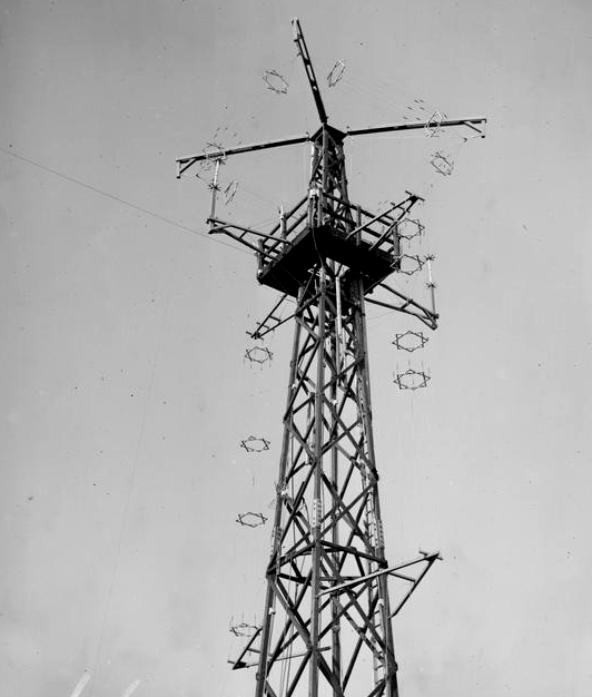 |
| October 24, 1944: Attached to the lattice mast at the Southwold station
were some vertically and horizontally polarized wire cage dipoles. A physical
characteristic of this antenna type are the wire spreaders which resemble
the 'Star Of David'. Horizontally polarized wire cage dipoles have
been installed on the ends of the topmost yardarms. (Imperial
War Museum photo # A 26123) |
 |
| This graphic illustrates the construction of a multiwire dipole antenna
which is horizontally polarized. At each end of the two segments, the conductors
are joined together. The outer ends are attached to support lines using
insulators while the inner ends connect to the transmission line.
The antenna can be fed with coaxial cable or open wire transmission line
and mounted in either a vertical or horizontal orientation depending upon
the desired polarization.. (Graphic courtesy ex-RAF Aerial Erectors) |
Maximum height of aerial was aimed at, and achieved by mounting
the dipoles on 20 foot masts clamped to chimney breasts on the roof of
the building. Chimney breasts are the brickwork or stonework from
the fire place up to the flat top on which is placed the chimney pot. As
many of the 'Y' stations were in old Coast Guard stations, the chimney
breast would be the strongest or easiest place on which to attach
the bracket for the mast/aerial. All through 1941, the enemy made
full use of R/T during his sorties, and in the absence of surface-watching
radar, the VHF stations were undoubtedly of great operational value. The
lack of accurate and sensitive DF equipment however, continued to be felt.Owing
to the heavy burden being shouldered by the Admiralty Signal Establishment
at that time, it was not thought practicable to ask for the development
of a special VHF DF system.
The DF Problem
Early in 1942, with the help of Dr. H. G. Hopkins at the National
Physical Laboratory, a survey of several Admiralty stations was undertaken.
This resulted in the development of a DF aerial system capable of an accuracy
of +/- 3 degrees.
The euiipment was housed in an octagonal wooden tower of Air Ministry
design. An open site near the main building was selected, the standard
aimed at being a field of 150 yards radius, clear of buildings, and other
reflecting objects. Every VHF station was thus equipped by the spring of
1943, but although the accuracy was greater than had been anticipated,
the sensitivity was considerably below that of the open dipole used with
the main interception receivers. The result was that on many occasions
when enemy signals were weak but readable on the intercept receivers,
they were inaudible on the DF receiver.
The loss was traced to the transformer in the aerial system, and a home-made
toroidal type was substituted as an interim measure with good results.
The problem was also submitted to the National Physical Laboratory once
more. Eventually a high efficient antenna transformer coupling, of the
screened loop type, was produced by Mr F. Horner, which incorporated a
remote controlled aerial tuning device easily accessible to the operator.
 |
 |
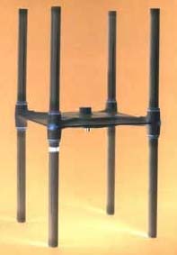
| This graphic shows the concept of an 'H'
Adcock attay. These were simply four, vertically polarized dipole
antennas. |
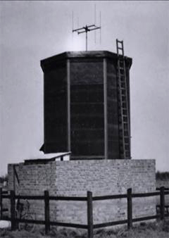
This is how the 'H' Adcock array looked in actual
practice. It was mounted atop an octagonal wooden tower of Air Ministry
design. The radio equipment was housed in the structure below. This was
the Beeston Hill 'Y' station installation (Image courtesy Wikipedia) |
Maintenance
The maintenance of the stations was carried out by experienced personnel
of the Civilian Shore Wireless Service. General supervision was undertaken
by technical officers on the staff of DSD who were also responsible for
the siting, building and equipping of new stations. In 1943, the efficiency
of the organization was greatly increased by the acquisition of suitable
signal generators, output meters and frequency measuring equipment.
Records were kept showing the sensitivity figures for all receivers,
which were re-aligned whenever necessary. Accurate frequency measurement
was an important requirement at all shore stations, because enemy aircraft
operating in separate groups used slightly different wavelengths. It was
necessary therefore to ensure that bearings at two or more stations were
taken on identical frequencies. The equipment used was a GEC crystal wave
meter which had an accuracy to within 0.1 MHz in the range 30 to
130 MHz. With all VHF aerials, low loss feeders were used. Their
attenuation was approximately 2 decibels at 200 MHz.
Masts
In order to simplify the erection and subsequent inspection and maintenance
of the dipole aerials, wooden lattice masts were erected at every station
in 1942. These were 70 or 90 feet high, and in the final design,
they incorporated a balcony some 20 feet from the top, which greatly facilitated
the fitting of aerials. The mast was sited as close to the watchroom as
possible in order to reduce the feeder length to a minimum.
Receivers
The standard VHF receiver at all stations was the Hallicrafters S 27D
(27.8 to 143 MHz). In 1941, a contract was placed with the Plessey Co.
for the design and manufacture of a VHF receiver, in order to avoid complete
reliance on the continued supply of American equipment. This resulted in
the production of the 13 tube Plessey RL 85 receiver (27 to 84 MHz in 3
bands), which was of robust construction, and which gave very good service.
Its measured sensitivity was slightly greater than the S27, but its overall
performance somewhat inferior. In particular, its RF circuits did not provide
such a high degree of discrimination as did those of the S27.
A few Marconi type RG 43 receivers were also used but
they did not prove to be as popular with operators as the Hallicrafters
or Plessey sets. This may have been due to the design of the main tuning
control, which was most tiring if used for a long period. There is no doubt
that the Hallicrafters S27 receiver won the prize on practically
all counts; it supported amplitude and frequency modulation and had an
efficient S meter. Its main tuning drive was practically faultless with
an exceedingly smooth action and an excellent vernier dial.
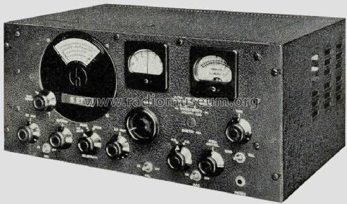 |
| The Hallicrafters S27D receiver was the standard
VHF receiver at 'Y' stations. The variant in the photo is unknown. (Courtesy
Radiomuseum.org) |
 |
| Plessey RL85 (27 to 84 MHz) receiver front panel. Click on the image
to download the service manual. Note that the schematic is missing. (Courtesy
Collingwood Heritage Collection) |
| Looking for a photo of the Marconi RG43 (Contact:
jerry.proc@sympatico.ca |
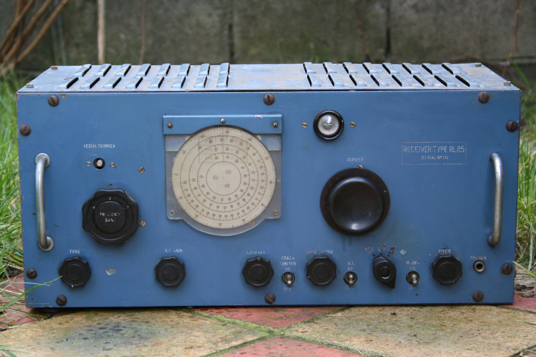 |
RL 85 in colour. Click on image to enlarge. (Provided
by Clive Kidd) |
HF Watch at VHF Stations
A subsidiary W/T watch was kept at most VHF stations, chiefly in connection
with transmissions from enemy coastal W/T stations and vessels concerned
with Harbour defence. The VHF stations were favourably placed for the reception
of these transmissions and in general special aerials were not necessary.
The receivers used were the National HRO, the Hellicrafters SX 28 and the
Admiralty Pattern B29.
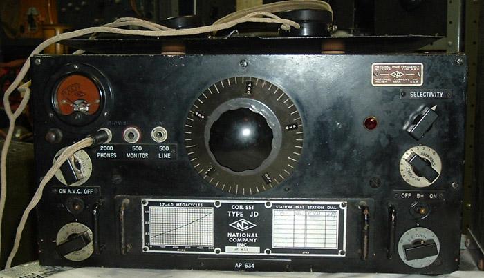 |
| HRO receiver (Photo by Andre Guibert) |
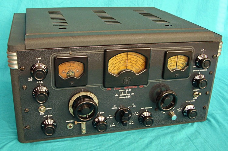 |
| SX28 receiver (Courtesy Western Historic Radio
Museum) |
 |
| B29 receiver (Photo by Ray Robinson VK2ILV) |
| Receivers used for the HF watch at 'Y' Stations |
Facilities Provided For Non-Morse Investigation
Although this history is mainly concerned with the reception of German
R/T, the technical record would be incomplete without a brief description
of the facilities provided at VHF Stations for noise investigation. This
equipment was serviced and maintained by the VHF technical staff at certain
stations which were of a dual purpose nature. Early in 1942 it became evident
that a Naval watch for signals of a non-Morse character was essential.
Included in this category were the following types of enemy signals:
Radar transmissions
Navigational beacons
High speed communications
Radio teleprinter links
IFF Transmissions (Identification friend or foe)
Electronic navigational aids
Jamming transmissions
Meteorological balloon transmissions
Guided missile transmissions
Noise investigation involves the use of a wide assortment of equipment
and presents many problems which are not encountered in Y work. A noise
station had to be equipped so as to cover the complete range of frequencies
from M/F to UHF. It should be able to DF any signal heard; and it
should be able to record and photograph any signal. Most of the identification
was done visually rather than aurally - i.e. by the use of a cathode
ray oscilloscope. In addition, it was essential that the audio frequency
be measured, and the polarization of the transmission determined.
A start was made at the Abbot's Cliff Y station, near Dover. A small
watchroom was equipped with the limited amount of gear available at the
time and operated by a few Wren W/T operators who were gradually trained
in their new duties by civilian representatives of the Admiralty Signal
Establishment. Aerials used at this time were plain dipoles and dipoles
with corner reflectors. A jacking system was employed to enable the DC
or AC output of any receiver to be viewed on an oscilloscope.
After some months it was evident that further noise stations were
necessary, and accordingly noise watchrooms were provided at the Ventnor
and Southwold Y Stations. Additional equipment was becoming available,
and it was possible both to make recordings and also to photograph any
transmission. These three stations, at Abbot's Cliff, Ventnor and Southwold
produced a mass of data for subsequent analysis, and eventually Admiralty
approval was given in June 1943 for the building of four Y and noises
stations. The sites chosen for these were at Southwold, Abbot's Cliff (near
Dover), Ventnor, IOW and Coverack, Cornwall. It will be seen that four
of the stations were suitably placed to provide coverage of the French,
Belgian and Dutch coasts.
The buildings and layout, designed in specification DSD9 were standardized
as much as possible. The accommodation consisted of:
* Noise Watchroom (approx 28 x 16)
* Main Building Y Watchroom (approx 20 x 16)
* Test and Maintenance room
* Photographic development room
* Office
* Toilet facilities
* Emergency supply power house
* D/F Tower - 30 to 100 MHz with vertical polarization of antennas
* Two D/F Huts - 100 to 600 MHz - with vertical and horizontal
polarization of antennas
Aerials
The standard VHF and UHF aerial system consisted of multiwire, centre-fed
dipoles . Four aerials provided coverage in the 30/60 MHz, 60/120 MHz,
120/240 MHz and 240/480 MHz bands These were vertically polarized.
In addition, four horizontal aerials covering the same ranges were also
used.
The H/F system was supported between four 70 foot lattice masts, and
consisted of four wideband, centre-fed dipoles covering the range 2 to
16 MHz. These were omni-directional. The UHF aerials were connected via
twin feeders to an aerial exchange board, then to the receivers. The HF
aerials were connected by underground coaxial cable which fed wide band
amplifiers and an aerial exchange board. Thus, several H/F receivers could
be used on the same aerial without cross-modulation.
Layout of Noises Watchroom
For ease of operation, it was found convenient to group two receivers
together so that one operator could use either at will. Associated with
each pair of receivers were a cathode ray oscilloscope, a Beat Frequency
Oscillator and a small jackboard. All the controls being in reach, the
operator could use either receiver and by means of the jackboard, either
audio output could be selected.
The bench wiring was designed to be as flexible as possible. Each bench
carried a master jackboard which enabled any desired combination of equipment
to be used. A connection from the jackboards to the telephone exchange
switchboard enabled a signal to be put out to the telephone line.
At Southwold, two long wire aerials were erected - one was aligned
to the North Dutch and German coasts while the other was aligned to the
Western coast of Norway. These HF aerials proved most efficient in practice.
Their directional properties greatly improved the signal-to-noise ratio
on weak signals.
ABBOT'S CLIFF
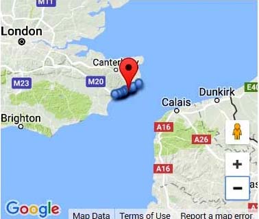 |
| Abbot's Cliff location. (Image courtesy Google Maps) |
COVERACK STATION
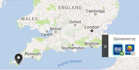 |
| Coverack station location. (Image courtesy
Google Maps) |
EASTON BAVENTS STATION
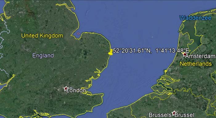 |
| The pin marks the actual location of the former
Y station. East Bavents is the nearest town. (Image courtesy Google
Earth) |
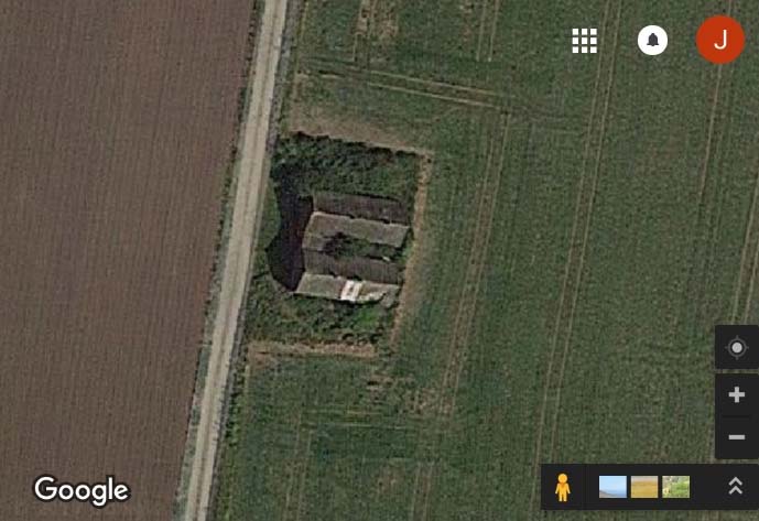 |
| At coordinates 52°20'31.61"N, 1°41'13.48"E , this is
all that remains of the Easton Bavents site as of November 2017. Just to
the right of the photo is the North Sea (Image courtesy Google Maps) |
SOUTHWOLD STATION
Researcher Stuart Rayner provides this information
about the Southwold station. "My interest is in the
Southwold 'Y' Station. It was located at the most Easterly
point of England. During WWII, a Naval 'Y' (W/T or R/T intercept)
station was set up in a big house overlooking the sea. It was part of a
string of 'Y' Stations along the UK East and Southern coasts. These stations
were manned by WRENS. Southwold was expanded in 1942 to include noise
intercepts. It was only one of four such stations The others were Abbots
Cliff (Dover), Ventnor (Isle of Wight) and Coverack (Lizard Peninsula).
In 1943, new watch rooms were built not far along the coast at Easton Bavents.
One watch room was designated 'Y' and the other 'N.
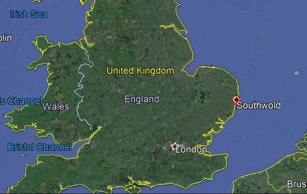 |
| Southwold station location. (Courtesy
Google Earth) |
 |
| Floor plan of the Southwold station as drawn
by Stuart Rayner. Download image to enlarge. |
At the Southwold station, the 'Y' hut contained the Y
watch room, the test/ maintenance room and an officers room. The huts were
linked with a single entrance having wash facilities between. The 'N' hut
contained just the 'N' watch room which was larger than the Y watch room
and another area which was a photographic room. There was also a
large hall in this hut. One interesting aspect is that the 'noise' watch
room had a Faraday Cage around it. It was the only room to be plastered
since the plaster held the wire mesh against the brick wall. It was the
only room to be plastered in this manner. When the asbestos sheeting was
taken off the roof, it could be seen that wire mesh was sandwiched
between the asbestos and the boarding underneath. There were also two loops
either side of the windows, where presumably the metal shutters over the
windows (confirmed metal by the hut owners) could be connected.
In a source document used for this web page (ie A History of the
R/T Y Organization Ashore and Afloat) one section says that aerial exchange
boards were avoided while another section says they were used. Stuart Rayner
believes that he can explain this apparent contradiction. " You can see
an aerial exchange board in the Imperial War Museum photograph of the Noise
watchroom, but not in the Y watchroom. I think the preference was to plug
the aerial directly into the receiver where they could, which was relatively
easy for the Y watchroom. In the Noise watchroom they would not have
been able to fit in the number of receivers for the number and type of
aerials, so it was simpler to have one or two workstations and an exchange
board, although this would have limited what they could monitor at any
given time".
There is also a series of Admiralty photographs taken in November 1944
when the Southwold station was operational. These twelve photographs are
held by the Imperial War Museum and can be seen at the following URL:
http://www.iwm.org.uk/collections/search?query=Southwold&items_per_page=10
As one can see, the interior photographs of Southwold are titled
by Watchroom and only one photo was taken of the Noise watchroom.
 |
| This is a photo of the 'N' hut at the Southwold station. The
deliberate fogging in the photo has been minimized as much as possible.
©
Imperial War Museum Photo #A 26125 |
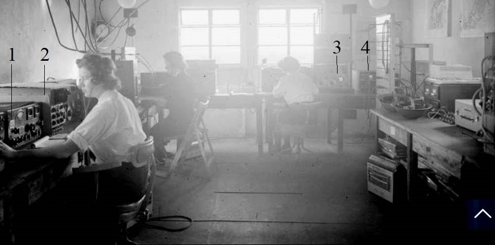 |
| Equipment identification in the N watchroom:
1- The receiver in front of the Wren is believed to be the Hallicrafters
S-27D. An S-27C manual
can be found here. (Courtesy Collingwood Heritage Collection)
2- Cossor Oscilloscope Type 3339.
3- G205 Oscillator. Commercially
known as a BSRL50A or BSR L50B . This oscillator could be used to
produce a signal to beat with and thus measure any modulation from the
transmitter of interest,
4- Not identified at this time.
© Imperial War Museum Photo #A 26125 |
 |
| October 24, 1944: The interior of the Test Room at the Southwold station.
(Imperial
War Museum photo # A 26129) |
The 'N' hut was the one closest to the tower with the more
complicated aerial sets, which were directly linked into the respective
huts through conduits in the walls. The experts are having difficulty with
what the different aerials were used for although the present opinion is
that the very top of the N tower could probably be rotated to enable direction
finding.
In addition to this, is that there are some recordings from a shellac
disc available on web sites of noise intercepts made at Southwold in 1943.
These can be found at:
https://www.youtube.com/watch?v=cLG1Q-z-1e0
http://www.cdvandt.org/fading-wartime-sounds.htm
They conclude that the recordings are of jamming and one of a radar
transmission, but they also think that voices can be heard in the background.
It is possible that the recordings were made from a tannoy (a sound-amplifying
apparatus used as a public-address system) in the room? When I was making
the survey, it was quite evocative playing these recordings in the room
they were probably recorded in."
VENTNOR STATION
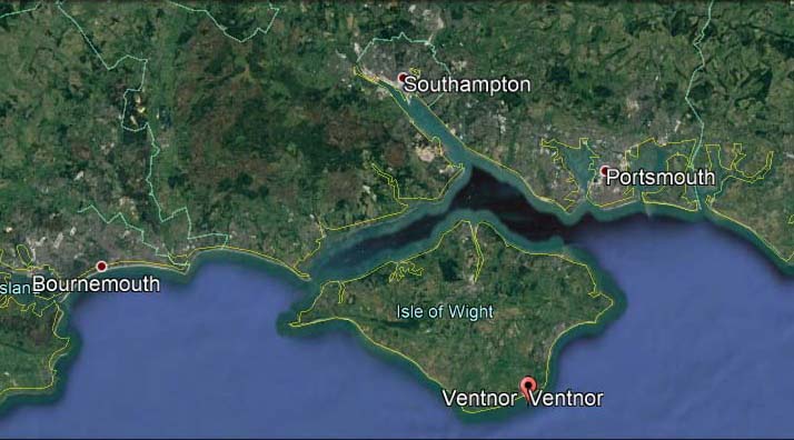 |
| Ventnor station location. (Image Courtesy
Google Earth) |
TRAINING INFORMATION FOR NOISE ANALYSIS
CAFO (Confidential Admiralty Fleet Order - see note [1]) 1907
issued on August 31, 1944 defined the additional training required
for personnel performing 'noise' intercept work att 'Y' stations.
In this explanation, the following terms apply.
Ldg Tel = Leading Telegraphist.
(S) = Special
Wren (S.O.) is WRNS Special Operator
(N) = Noise Duty qualified
Before additional training could begin, personnel had to meet the standards
set out in CAFO 1128/43 for Telegraphist (S) and CAFO 1182/43 for
Wren S.O. Personnel suited for additional training were selected
from a pool of volunteers . This advanced training was to be 2 months in
duration. People not suited for 'noises' work were to remain in the Telegraphist
(S) and W.R.N.S. branches. Personnel who qualified for 'noise"
work would continue to wear the same badges as Telegraphists
(S) and Wrens (S.O.).
These were the percentages required for a passing grade for
the listed examinations
| EXAMINATION TYPE |
Ldg. Tel (S) (N) and
Ldg. Wren (S.O.) (N) |
P.O. Tel. (S) (N) and
P.O. Wren (S.O.) (N) |
|
|
|
| Buzzer - receiving |
95% |
95% |
Buzzer - receiving in Japanese Morse;
200 message symbols in 3 minutes |
Nothing
indicated |
95% |
| British and foreign W/T procedure (paper) |
80% |
90% |
| Technical (paper) |
80% |
90% |
| Technical (practical) |
80% |
90% |
Organizational and duties of personnel
in charge (paper) |
80% |
90% |
The Buzzer receiver standard consisted of the followung minimums:
* Plain language English - 23 wpm
* Plain language foreign- 23 wpm
* 5 figure cipher - 14 wpm
* 4 letter code - 25 wpm
* Short messages - 20 wpm
CAFO 1907 also expands on the standards of knowledge. for the W/Y technique.
The following table rates knowledge levels into A and B categories.
A= Detailed knowledge of the subject
B = Good general knowledge of the subject, omitting details.
| KNOWLEDGE ITEM |
Ldg. Tel (S) (N) and Ldg. Wren (S.O.) (N) |
P.O. Tel. (S) (N) and P.O. Wren (S.O.) (N) |
|
|
|
| Knowledge sufficient for purposes of recognition
of Allied and foreign W/T procedures . Both of the fighting forces and
commercial. |
B |
A |
Knowledge of all kinds of receiving and recording
apparatus in the station which is doing the receiving. |
B |
A |
Knowledge of the method of investigation of signals,
analysis, treatment and disposal of material received. |
B |
A |
Operation and adjustment of all types of receiving
and D/F and recording apparatus in the station doing the receiving |
A |
A |
CAFO 1907 contains more detailed information about the level of knowledge
required to qualify for noise analysis. Only highlights have been extracted
and posted here.
LINGUISTS
In the book "They Listened in Secret, Edited by Gwendoline Page" oral
histories were derived from the the German linguists who had a lot of memoirs
of their time in the ' Y' Service. There are three sections written by
Freddie Marshall who ran the Special Duty linguist section from its inception
through to the end of the war. He identified how it was set up, the required
training and how it progressed throughout the war.
Freddie identified the need for Wren German linguists in early 1940
after the evacuation of Dunkirk, to take over from the male German linguists
at the 1st Y Station at Dover. Male linguists were required on vessels.
A Special Duties section was set up under the ultimate direction and
control of NID9 at the British Admiralty, growing up to be a private army
of NID9, almost without reference to Naval Commands. Local Wren commanding
Officers had no idea what went on at the Y Stations, nor did they have
any authority over them and were not allowed anywhere near the intercept
rooms. German intercept training started at the Royal Naval College Greenwich,
the first course starting 22nd July 1940. The attendees had to sleep in
the basement in hammocks during the air raids. After January 1942, the
course was held at RNTE Southmead at 22 Inner Park Road, Naval personnel
went through the same course at Southmead as did the Wrens. The Wrens were
taught the likely R/T traffic from E-boats and provided the Wrens
with German nautical terms and the English equivalents they were likely
to hear. Traffic was given in plain language and coded commands in German
phonetic alphabet.
There was a shortage of German speakers at the beginning of the war
and initially they were channelled into R/T intercepts, being the only
people who could complete this task. The Y Stations expanded as German
linguist Wrens became available. Wrens also served at the intelligence
centres where they translated the W/T intercepts. Later on, linguists became
W/T operators, as the German empire shrank, however the Southwold station
remained operational until 1945 as the S-boats were still operating up
until April that year.
RADAR COUNTERMEASURES (R.C.M.)
Noise operators were trained to recognize non-communications emissions.
Today we would call them ELINT operators. Their primary task was to find
hostile emissions and recover as much parametric data as possible from
them, so the data could be recycled for future use in identification .
(CAFO 91/45 para 3). Some of the Noise operators were also taught how to
use jammers - that is non-communications jammers - typically against radars,
German radio controlled bombs (missiles) and other emitters.
Noise operators served both on land (Wrens and Matelots) and at sea
(Matelots). Jammer operators served mainly on land because, with
few exceptions, ships did not have radar or comms jammers (CAFO 1569/44).
Such systems were too big as space on ships was limited. They were
power hungry, heat generating sources of RF which interfered with
ship's own systems. When not used, they would have also taken up valuable
space. There were a few exceptions to this.- the primary ones being J Ships,
specially selected and fitted with jammers in support of Operation OVERLORD.
There were also a couple that served in the Mediterranean with comms jammers,
to disrupt the Italian R/T air-to-air and control circuits.
The main land-based radar jammers involving Royal Navy personnel were
located in the Dover area. It is believed there were some on the Isle of
Wight, but there is no proof at this time. These are believed to have been
targeted at aircraft emitters and aircraft receivers and in particular
to interfere with the German guidance beam systems that were used to guide
the bombers to find their High Value Targets in the UK.
L/Tel(S)(N) and POTel(S)(N) were fully qualified in noises and RCM
and served both ashore and afloat. These ratings were already (S) trained,
so they were well aware of foreign Morse and R/T intercept techniques,
and with some limited language ability; they were aware of German (and
Italian) codes and cyphers) and capable of carrying out traffic analysis
when a new circuit was found. Noises and RCM requirements appeared rather
late in WWII mainly from around mid-1942 onwards
By 1945, candidates for Leading Telegraphist (S) (N) and Petty Officer
Telegraphist (S) (N) given a practical examination in Radar Counter
Measures (R.C.M.) on the following equipment.
* Type 78T was the predecessor to the Type 91 CFXR, however no details
are available at this time.
* Type 91 CFXR radar (350 to 800 MHz) was used in conjunction with
the P58 and Marconi 1147/A receivers. It was the Admiralty's intention
to replace type 91 CFXR with American type TDY, however, WWII ended before
this could be implimented.
* Type 650 series missile jammers [3] were not actually introduced
into service until 1944 Then came type 651.
* American type TDY jammer (90 to 800 MHz) per CAFO529 page 6.
In all of this, it was *not* the Admiralty's policy to jam German
communication circuits [2]
NOTES:
[1] These CAFOs and AFOs were the way that the naval hierarchy disseminated
info and management instructions to RN Personnel both ashore and afloat.
The instructions might be temporary or could be incorporated into Kings
Regulations and Admiralty Instructions or one of the mass of handbooks
and operating manuals that abounded (and still do to this date).
[2] Per CAFO 529 Page 6. As a rule, ships generally did
not have comms jammers. They took up too much room, ate too much power
and generated too much heat for very little use. There was more to be gained
by listening to a comms circuit than by jamming it. There were exceptions
to the general rule, mainly based on strategic grounds, such as Operation
Overlord.
[3] As a trial, the first ship fitted with a Type 650 radar jammer,
was HMS Woodpecker in 1944. The Type 650 comprised a 5AD and 5AE transmitter
and a P101 and B38 receiver using an APW dipole aerial. It is believed
that this trial was part of the proving process for Operation Overlord.
Webmaster's note: If anyone can contribute additional
content (ie noise analysis or RCM ) to this story, please contact: jerry.proc@sympatico.ca
Contributors, Credits and References:
1) Stuart Rayner <stuart.rayner(at)mac.com>
2) Extracts from A History of the R/T Y Organisation
Ashore and Afloat, July 1940 to May 1945, TNA HW8/99
3) Beeston Hill photo https://goo.gl/images/5o5nzd
4) https://www.radiomuseum.org/r/hallicraft_uhf_receiver_s_27_s27.html
5) http://www.iwm.org.uk/collections/search?query=southwold&items_per_page=10
6) http://www.hariggers.co.uk/odds.htm
7) CAFO 1907 Pages 12 and 13
8) Clive Kidd <cjckidd(at)waitrose.com>
9)
10) Imperial War Museum photos of the Southwold station
11) CAFO 91, Item 6
12) CAFO 529 page 6
Back to RFP/TINA document
May 3/24