 |
| The Maggie detector principle was based upon the effect of high frequencies on the magnetic characteristics of iron. (Photo via Le Musée Québecois de la Radio) |
The requirement for communication between ships and between ship and shore must be as old as the first time that early man floated down a stream on a log and discovered that he couldn't yell loud enough to get help. For thousands of years, communications consisted of simply two types - sound and visual. Bells, whistles and horns were used for sound signalling, while visual signalling employed flags, lights and later on, semaphore signalling. Naturally enough, this form of communication required the development of codes in order for the sound or visual signalling to have any meaning. It soon became evident that even a single flag in a prominent position could serve to transmit a clear and comprehensive message.In spite of all of the advances in technology that have been developed since the first introduction of wireless sets, visual and sound signals still form an important part of maritime communications today. Under the "International Regulations for the Prevention of Collision at Sea", ships in sight of one another are still required to communicate their intention to alter course by sounding a prescribed signal on their whistles or foghorns. Vessels proceeding in fog, are required to sound appropriate signals. Ships meeting each other at sea or vessels entering port communicate using signal flags and the INTERNATIONAL CODE.
Allied warships carry a code book containing thousands of combinations of one, two and three or more letters and numerals for administration, manoeuvring and combat. These codes can be signalled by radio telephone, flashing light, semaphore, flags or pendants. It is also sufficient to say that visual signalling using flags, flashing lights or even infra red is a simple, dependable and relatively secure means of communications between ships in certain situations.
Throughout the following chapter, there are many references to the Royal Navy. This is intentional, because the Royal Navy was quick to adopt new developments in radio technology and invariably, navies of the Commonwealth member countries tended to follow the technological lead as set by the Royal Navy. This of course, included the Royal Canadian Navy
During the 1830's and 1840's, land line telegraphy using Morse Code was developed and expanded to cover the British Isles, the European Continent and North America. For ships at sea, it was a totally different matter. Once they were beyond the horizon, they were totally isolated from communicating with the rest of the world until such time as they reached the next port or were able to pass messages via another vessel. The application of the telegraph to naval communications seemed new and very unwelcome when it was first introduced in the mid-nineteenth century. A major limitation to this system, was the fact that the ship had to come into a foreign port in order to communicate. A response from the home authority could be instantaneous or not. Although slow to incorporate this new technology, the Royal Navy eventually adopted the system in 1847 to replace the mechanical semaphore relay system linking London, Portsmouth and Gosport. Undersea cable service was expanded to Europe in 1850, trans-Atlantic in 1866 and worldwide by 1870. By 1878, the British Admiralty was connected to all of their major bases throughout the world.Royal Navy Communications Network - 1878 (Courtesy Electronics and Sea Power)
In 1888, a German scientist by the name of Hertz, published some experimental data which indicated that electromagnetic waves radiated in all directions and moved at the speed of light. Another scientist, Sir William Crookes, forecast in 1892, that electromagnetic waves (EM) could be used for communications. Captain HB Jackson, a scientifically minded officer at the Royal Navy's Torpedo School, constructed a wireless set in 1895 that would send signals from one end of a ship to the other end. The following year, he performed the same experiment from ship to ship within harbour. In each case, the object of the exercise was to ring an electric alarm bell. By September of 1896, Captain Jackson met Guglielmo Marconi at a demonstration on Salisbury Plains where a signal was transmitted 1.75 miles using an aerial system devised by the Russian scientist Popoff. Also included in the display, was the addition of a telegraph recorder.In July of 1897, Marconi successfully communicated from the naval dockyard in La Spezia, Italy to the armoured cruiser San Martino which was 11 miles away at sea. The equipment consisted of a spark gap transmitter, a wire antenna and 250 watts of power provided by a battery. Whenever the key was pressed, the result was an unmusical note similar to the background atmospherics over a very broad band of frequencies. There was no way to measure wavelength and tuning was in its infancy. The frequency of transmission was therefore dependent on the size and configuration of the aerial. As a result, there was only one wireless channel as the electromagnetic energy leaving the antenna would cover an extremely wide frequency band.
The receiver consisted of a similar aerial and the use of a "coherer" which detected EM waves. A battery operated circuit then operated a telegraph "inker" which displayed the signal visually on tape. There was no means of tuning the receiver except to make the aerial the same size as that of the transmitter. It could not distinguish between atmospherics and signals and if two stations transmitted at once, the result was a jumble of unintelligible marks on the tape.
There was a notable characteristic about the spark gap transmitter. On reception, each signal sounded just a little bit different than the rest. This signal characteristic was usually determined by electrode gap spacings, electrode shapes, and power levels inherent to each transmitter. With a little practice, one could attach an identity to the transmitting station based on the sound in the headphones. From a security viewpoint, this was not good for any navy, as a ship could eventually be identified by the tone of its transmitted signal. On the other hand, this signal trait was a blessing, otherwise, there would have been no hope of communication as 'spark' produced signals were extremely wide. By 1924, frequency and power limitations were applied to spark gap transmitters and they were totally banned in the United States by 1927. Many amateur radio operators actually gave up their licence, rather than convert to the new method of producing CW by employing a vacuum tube. For commercial and military usage, the arrival of newer technology was a godsend.
By 1899, Marconi was able to operate radio equipment at ranges of 30 miles or more. This demonstration enabled him to raise money and the British Marconi Company was formed. Two years later, an American subsidiary was born and it dominated the British and American marketplace until the formation of the Radio Corporation of America in 1919. Many different sets were being developed for communications, however, Marconi's sets proved to be superior and were by far, the most widely fitted sets on ships. At this stage, it should be noted that the Royal Navy was already looking at three distinctly separate uses for wireless communications.
The first use was to communicate from ship to ship with special emphasis on scouting and reporting on the position of the enemy. During the annual manoeuvres of 1899 and 1900, the value of wireless in this role was clearly demonstrated. As more and more equipment was installed aboard ships, the problem of mutual interference became critical as the sets lacked selectivity. The problem posed by the interception of messages by other than the intended addressee was soon recognized with the attendant requirement to use some form of secret code. These problems still exist today even with the proliferation of radio channels and the adoption of high speed fully automatic encryption systems.
The second use was to send and receive messages to a ship when it was within range of a land based station. Messages to and from the ship would be relayed to the telegraph network and then to their ultimate destination. A third use for wireless was to broadcast messages to ships at sea within a 1000 mile range of Poldhu, England.
On December 12 1901, Marconi established trans-Atlantic communications from Poldhu to St. John's, Newfoundland using a 25 kw alternator driving a spark gap transmitter coupled to an umbrella shaped aerial on a wavelength of 366 metres. The first transatlantic radio communication consisted of the single letter "S". In the following year, he maintained contact with the Cunard liner Philadelphia at ranges of 700 miles by day and 1500 miles by night.
Forced out of Newfoundland by the Anglo-American Telephone Company, Marconi persuaded the government of Canada to allow him to re-erect a radio station at Glace Bay, Nova Scotia. He soon realized that his company would not survive if it relied entirely on the field of international communication. Competition was too great in this business.It became apparent that the most promising field was marine installation, where he would not be competing with the cable and wireless companies. Marconi had the backing of Lloyd's of London and the Admiralty and in 1901 he obtained contracts to equip both naval and merchant ships. His plans for marine wireless were large and ambitious. He hoped to control all of the basic patents of radio and to equip the ships of all nations with his apparatus. Plans also called for the construction of a chain of shore stations around the world from which to control the ship-to-shore traffic. Marconi's plans almost succeeded, but the aggressive tactics aroused antagonism which eventually led to a reduction in business.
Marconi had two other developments during this period. The first of these was a transmitter equipped with a separate oscillator coupled by a transformer to the aerial. The resulting output was found to be on two separate wavelengths. TUNE A at 100 metres with a range to 50 to 70 miles and TUNE B on 270 metres with a range of 80 to 150 miles. It was also discovered that Poldhu, which was operating on 366 metres would not interfere on either of these tunes. In this era, the Royal Navy chose the term TUNE to express an operating wavelength.
Secondly, was the development of Marconi's Magnetic Detector or MAGGIE which replaced the coherer in the receiver and allowed the use of headphones. It was much more sensitive than the coherer and allowed CW transmission speeds to be raised from 10 to 20 wpm since the telegraph inker was no longer needed. Originally, Marconi only leased his equipment to ships and supplied his own trained operators. The Royal Navy, however, insisted on outright purchase. Eventually, competition from German and American firms caused Marconi to change his policy. The U.S. Navy in particular were violently opposed to Marconi dominating the marine wireless business and to ensure fairness, they subsidized Marconi's German and American competitors.
|
| The Maggie detector principle was based upon the effect of high frequencies on the magnetic characteristics of iron. (Photo via Le Musée Québecois de la Radio) |
In 2018, a pre-WW1 document surfaced which listed War Signal Stations on Canada's East coast. It has been included here since it was part of Canada's maritime history. Here is what this document tells us in order of importance.Prior to WW1, these War Signal stations were using the old Marconi Mxx call signs before the creation of the International call sign blocks at the London Radio Convention of 1912. After 1912, Canada was assigned call sign blocks VAA to VGZ and Newfoundland VOA to VOZ. Newfoundland was still under British jurisdiction at this time. It appears that the Newfoundland stations built by Newfoundland were assigned the VO prefix, and the Newfoundland stations built by Marconi were issued Canadian call signs. For example Cape Ray Newfoundland was VCR, Cape Race Newfoundland was VCE, Bell Island, Newfoundland VCM and so on. Bull Harbour, Newfoundland was VOH and there were others. Newfoundland still retained the VOA-VOZ call sign block even after becoming a Canadian province in 1949.
For the Barrington site, there was no power given. Instead the entry says 10 inch coil. This suggests that a spark gap transmitter was in use and it was probably the same for the rest of the stations. When applying LAT/LONG coordinates in Google Maps, some of the stations are placed over water instead of land. This is puzzling. Some of the stations operated for only part of the year. The reason for this is not known at this time.
In 1904 and 1905, the Royal Navy adopted transmitters fitted with alternators and accepted the use of MAGGIE and headphones. A wavemeter was developed to measure wavelength. Selectivity of receivers improved. Roof aerials or "flat tops" were introduced as well. All of these improvements permitted signalling speeds of thirty words per minute.From 1900 to 1910, there was little profit in the radio business. The tragic sinking of the Titanic in 1912 focused public attention on the importance of ships being equipped with radio and the necessity for maintaining 24 hour radio watch. After the Titanic sinking, many countries required that ships over 500 tons be equipped with radio. This caused the demand for marine radio gear to soar and the Marconi Company was able to declare its first dividend in 1913.
Royal Navy communication stations in the 1915-16 period. (Courtesy Electronics and Sea Power)
WAVELENGTHS AND INTERFERENCE
The main problem of the day was interference and congestion of the ether. Most countries could only transmit on one frequency and the A and B Tunes of the Royal Navy were also used by merchant ships equipped with Marconi apparatus. Some countries believed that the construction of high powered stations would overcome the interference problem by sheer brute force. Construction of some high powered stations actually started. A school of sober, second thought, believed that these stations would jam all communications within 100 miles of their location. Eventually most countries deferred the construction of those high powered stations and continued with the extension of their network of low powered coastal stations. The future development of wireless telegraphy clearly depended on tuning so that a number of wavelengths could be used simultaneously. During the first decade of this century, all of the major navies of the world embarked on experiments on the installation of wireless both ashore and afloat. Space does not permit the discussion of results, however, reference can be made to any authoritative account of the Russian-Japanese War of 1904. This was the first naval war in which wireless telegraphy played a significant role.
In 1906, an International Radio Telegraphic Conference was held in Berlin. It established two new wavelengths for public commercial radio service, namely 300 metres (1000 kc) and 600 metres (500 kc). Shore stations not used for public service were allowed to use any wavelength below 600 metres or above 1600 metres (187.5 kc).
The Royal Navy proceeded to establish TUNES as listed: below
| TU NE | WAVELENGTH
(meters) |
FREQUENCY
(KHz KHz) |
USE |
|---|---|---|---|
| A | 100 ( See table note below) | 3000 | Shared between Royal Navy and merchant ships. |
| B | 270 ( see table note below) | 1111 | Shared between Royal Navy and merchant ships. |
| C | 900 to 1200 | 333 to 250 | This wavelength is relevant to 1913. It was an experimental wavelength in 1905 |
| D | 212 | 1415 | For use by Royal Navy Destroyers |
| F | 1000 | 300 | Royal Navy use |
| P | 300 | 1000 | Commercial wavelength; |
| Q | 600 | 500 | Commercial wavelength |
| R | 788 | 380 | Reserve RN frequency in case of jamming by the enemy. |
| S | 1000 | 300 | Royal Navy - Keep in touch with detached ships. . |
| T | 1273 | 235 | Royal Navy - Used for ship to shore comm. |
| U | 1515 | 198 | Royal Navy - For communication with flagship. Also used to report enemy battlefleets. . |
| V | 1727 | 174 | See table below |
| W | 1970 | 152 | See table below |
| Notes about Tunes A, B and C. The wavelengths shown for Tunes A.and B in the table were extracted from the book "Electronics and Sea Power (1975)". The publication "Year Book Of Wireless Telegraphy and Telephony 1913" quotes Tune A as being 300 to 600 meters; Tune B as 600 to 900 meters and lastly, Tune C as being 900 to 1200 metres. Both set of values are shown here since it can't be determined which of the two are correct . | |||
As the need for ship to shore communications increased, the British Admiralty built more shore stations. In doing so they added more tunes and revised a few others.
| TUNE | WAVELENGTH | FREQUENCY | USE |
| (Meters) | (KHz) | ||
| U | 1527 | 190 | Communications with low power shore stations. |
| V | 1529 | 173 | Communication between Admiralty, Whitehall and Cleethorpes |
| W | 1987 | 150 | Communications between ships and medium power shore stations. |
| X | 2998 | 100 | Broadcast by Cleethorpes and North Front, Gibraltar |
| Y | 3660 | 82 | Communication between Horsea to North Front Gibraltar and Rinella, |
| Z | 4200 | 70 | Broadcasts by Rinella |
There is a contradiction with Tunes A and B. An article written by a Marconi operator in 1917 says that in 1911, Tunes A and B had a wavelength of 1000 and 2000 feet (304.8 meters and 609.6 meters)., These were later changed to 300 and 600 meters. In the book Electronics and Sea Power, Tunes A and B are shown to be 100 and 270 meters respectively. The discrepancy cannot be explained at this time.
In 1907, the new Destroyer Wireless radio was introduced into the Royal Navy. The associated receiver had coverage on TUNES D to W. At the same time, the first "INSTRUCTIONS FOR USE OF W/T SIGNALLING" were issued. This was standard in its day which allocated wavelengths for specific purposes such as broadcast, ship-to-shore communications, scouting net and guard.
Marconi's company was to remain dominant in the radio business for a number of years but its future was not bright. The rapid progress of CW telegraphy and the development of the vacuum tube were the main causes of decline. During the next decade, scientists worked hard to improve the performance of radio equipment. The invention of the triode tube by Lee DeForest encouraged the development of oscillators and amplifiers in transmitter design. These advancements eventually rendered the spark gap transmitter obsolete and for the Marconi Company, this meant the loss of a leading position in the field. At the same time, receiver performance continued to improve with the adoption of the crystal detector, a device called the Poulsen Tikker, and in due course the heterodyne receiver. The main challenges remained in accurate tuning and the limitation of bandwidth. Other ares of improvement lay in antenna design and the location of antennas aboard ship - a problem that continues to challenge naval architects and naval communicators to this day. Radio had very visible impacts on the shape of warships. Before 1914, many ships were given high masts because raising antennas made for greater radio range. It also made ships visible at greater distances and long wire antennas were particularity vulnerable to gunfire. Later, they tended to foul anti-aircraft arcs of fire. During World War II, the US Navy adopted much less efficient 'whip' radio antennas since they posed fewer problems in topside arrangements.Studying the operational history of communications during World War I is fascinating and several books have been written on the subject. Communications Intelligence involving intercepts and cryptology came into their own during this period. By 1914, naval signals were generally coded, but during the first war, the British managed to obtain keys to all of the German codes. Code breaking and other signals intelligence first revealed that the German fleet was at sea before Jutland. Long haul radio became so important during this period that the British made a goal for the destruction of the German radio stations in the Pacific. From a technical viewpoint, World War 1 brought little more than the spinning of an ever expanding radio web.
THE ROYAL CANADIAN NAVY IS ESTABLISHED
On March 29, 1909, a Member of Parliament, George Foster, introduced a resolution in the House of Commons calling for the establishment of a Canadian Naval Service. The resolution was not successful; however, on January 12, 1910, the government of Prime Minster Sir Wilfrid Laurier took Foster's resolution and introduced it as the Naval Service Bill. After third reading, the bill received royal assent on May 4, 1910, and became the Naval Service Act, administered by the Minister of Marine and Fisheries at the time. The official title of the navy was the Naval Service of Canada (also Canadian Naval Forces), and the first Director of the Naval Service of Canada was Rear-Admiral Charles Kingsmill (Royal Navy, retired), who was previously in charge of the Marine Service of the Department of Marine and Fisheries.
The act called for:
* a permanent force
* a reserve (to be called up in emergency)
* a volunteer reserve (to be called up in emergency)
* the establishment of a naval college.The Naval Service of Canada changed its name to Royal Canadian Navy on January 30, 1911, but it was not until August 29 that the use of "Royal" Canadian Navy was permitted by King George V.
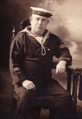
As a result of this act, the Royal Navy Canadian Volunteer Reserve (RNCVR) was established in May 1914 in Victoria, BC and undertook a strength of 1200 men from three distinct geographic areas: (1) Atlantic, (2) Pacific, and (3) Lake (representing inland areas). Following the general demobilization at the end of WWI, the RNCVR was disbanded on 15 June 1920. The need for a national economy and war weariness after "the war to end all wars," coupled with no apparent enemy or threat, led to even more drastic defence reductions.
Bill Weeks, a Stoker from the WWI era, is wearing the uniform of the RNCVR. The photo date is unknown. (Photo submitted by Gerry Sullivan) On 29 January 1916, a government Order in Council (P.C.162) was passed establishing a rank to be known as Wireless Operator in the RNCVR. There were six grades described.
Chief W/T Operator
1st Class W/T Operator
2nd Class W/T Operator
3rd Class W/T Operator
4th Class W/T Operator
LearnerThe Chief W/T Operator was to rank as a non-executive Chief Warrant Officer and the remaining grades to rank as non-executive Warrant Officers.
RANK BADGES
Chief W/T Operator Wings of Mercury and 1 RNCVR stripe without the curl below
1st Class W/T Operator Wings of Mercury with 3 stars below
2nd Class W/T Operator Wings of Mercury with 2 stars below
3rd Class W/T Operator Wings of Mercury with 1 star below
4th Class W/T Operator Wings of Mercury
Learner Wings of MercuryThe cap badges were to be the same as for non-executive Warrant Officers.
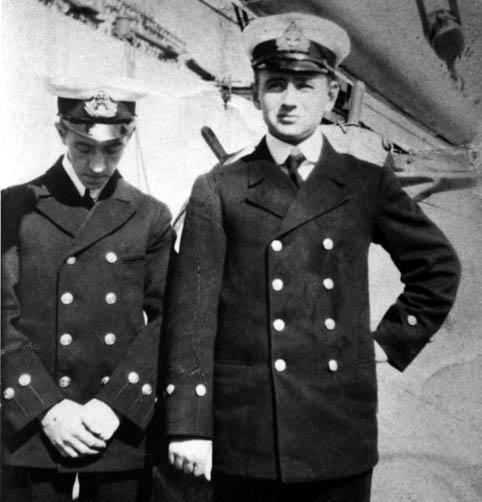
Ernie Wood (L) and Harris Brennan (R) as Wireless Operator Telegraphists RNCVR at HMCS STADACONA in August 1915. This photo shows the type of uniform worn by RNCVR Wireless Operator Telegraphists before the government Order in Council (P.C.162) was passed in January 1916. The naval radio operators were called Warrant Officer Telegraphist during WWI and held commercial radio licences.(Photo courtesy H.H. Brennan. Submitted by Spud Roscoe) As best as it is known, all Wireless Telegraphists held commercial licences and most if not all were operators before they joined the RNCVR. Some had been landline telegraph operators and passed their commercial licence and the Continental code just before joining. Some of these exams were held at Camperdown Radio VCS that eventually became Halifax Coast Guard Radio VCS.
From the Annual Report of the Department of the Naval Service, 1916, p. 20-1):
"On account of the confidential nature of the messages passing through the hands of radio telegraphy operators, and the secret instructions with which they must be entrusted during the present time, it was considered advisable to enlist in the Royal Naval Canadian Volunteer Reserve all the wireless operators in the employ of the department; for this purpose, the rank of wireless operator was instituted, and regulations were drawn up to meet the requirements in this connection. The operators have now been enlisted into the RNCVR."Coincidentally, the first such wireless operator in the Ledger Sheets for WOs, Mates and Commissioned Officers was: OFF VR-004, Harry Ambrose COADE. (The fourth entry!) Although Coade enlisted into the RNCVR on 1 Oct 1914 as a CPO Telegraphist, he was warranted as a Wireless Operator on 1 May 1916.With the navy facing drastic budget cuts after WWI, Rear-Adm Walter Hose proposed that the Navy be reduced to a single destroyer on each coast, and that the dockyards be reduced to the barest minimum necessary for maintenance and a small training base. To create national naval awareness, he suggested that the Royal Canadian Naval Volunteer Reserve, the RCNVR, now known popularly as the "Wavy Navy", be established in major cities across the country. On 1 March 1922, the day after Hose submitted his memorandum, it was initialled by the minister. On 31 January 1923, the Order-in-Council establishing the RCNVR was signed, and the first commission was given on March 14 to Lieutenant Frank Meade to establish a half-company in Montreal
The initial authorized strength of the RCNVR was 1,000 all ranks. Fifteen Canadian cities were earmarked for a division. Most were to be of Half-Company strength, which was 50, all ranks. These cities were Calgary, Charlottetown, Edmonton, Halifax, Hamilton, Ottawa, Prince Rupert, Quebec City, Regina, Saint John, Saskatoon and Vancouver. Three cities were ordered to man to a Company strength, which was 100, all ranks. These cities were Toronto, Montreal and Winnipeg. By the end of 1923, twelve units had been formed.
 |
|
|
BETWEEN THE WARS
Between the wars, a notable development in radio communications was the creation of the Naval Signals Branch in the RN. 'Bright Young Men' gravitated into this branch and discovered that one way to success was to be a Flag Lieutenant (ie - an Admiral's aide) specializing in naval communications and pursuit of the Admiral's daughters. This is not to say that they were not technically competent. One of the brightest of the BYM was Commander Lord Louis Mountbatten. As Fleet Wireless Officer for the Mediterranean Fleet, he organized monthly meetings of all Fleet Radio personnel. At one of these meetings, he casually mentioned the fact that he had been having his bath after polo and listening to his bathroom radio. (Having a radio in the 1920's was somewhat of a luxury). While listening, he heard a passing merchant ship ask the flagship for a time check. Suddenly he realized that the ship was a great distance away, and his curiosity made him ponder as to what was causing the radio waves to be propagated so far. He didn't know about skip at the time so he studied the phenomena to see how it could be applied to long haul strategic communications.In 1923, the Poldhu station began operating on 97 metres (3092 kc) with a power input of 1 kilowatt over ranges of 1,250 nm by day and 2,200 nm at night. The move into HF communications began in earnest in the years of 1926 and 1927 as the Royal Navy opened fixed services in the HF band to connect their worldwide strategic shore stations. This was done in order to supplement existing undersea cable services. Propagation research was basically trial and error as optimum frequencies were being determined for day and night conditions.
By the 1930's, broadcasts and ship to shore (S/S) nets had operated in the spectrum as high as 22 Mc and practical experience had also shown that high powered, low frequency broadcasts could be received to depths of 50 feet or more by submerged submarines. S/S traffic could be passed on five waves in the 4, 6, 8, 12 and 16 megacycle bands. Any ship could be answered by any station and the message relayed to its destination on the fixed services. At the outbreak of World War II, the Fleet Wireless organization was in a satisfactory state thanks to the ilk of Mountbatten, however, there was lack of voice radio in aircraft and poor communications with merchant ships.
Royal Navy Communications Network - 1938 (Courtesy Electronics and Sea Power)
HOW A "SPARKER" GOT HIS NAME
Spark gap transmitters were very rudimentary in the early days of radio. When the operator opened and closed the telegraph key, the apparatus produced an electrical spark at the both the spark gap and telegraph key. When the balls of the spark gap became sufficiently corroded, that caused the spark to fluff out and made the Morse signalling hard to copy. A transmission would then be sent from the receiving end - Clean Your Balls. The contacts on the telegraph key would also sustain pitting as as result of the interruption of current flow so they too had to be cleaned. So the radio operator who produced the sparks and the resultant radio waves acquired the nickname of "Sparker" .
When frustrated, spark gap operators frequently sent the acronym GTH which meant "Go To Hell". In this era, there were few company regulations or directive and no real policing of operator practices.
Select this link to see a generic diagram of a spark gap transmitter. Circa 1905 (Courtesy ARRL)
THE OBSOLESCENCE OF THE SPARK GAP TRANSMITTER
The radiation of damped wave trains from spark transmitters produced interference covering a wide frequency band. Owing to the limited number of available channels of communication in an ether already overcrowded, international regulations were devised to restrict and, gradually, almost eliminate the use of spark transmission.
Here is a comparison between the prevailing transmitter technologies of the post WWI era:
| THE SPARK SYSTEM | ||
| Advantages | Disadvantages | |
| (1) Robust and durable.
(2) Faults easily cleared. (3) Emits a wave, which forces its way well through interference. |
(1) Wasteful of power.
(2) Short range as compared with continuous wave generators. (3) Interferes badly. (4) Requires high insulation on account of initial peak voltages. |
|
| THE ARC SYSTEM | ||
| Advantages | Disadvantages | |
| (1) Robust and durable.
(2) Faults easily cleared. (3) Can be easily constructed to handle large powers. |
(1) Slow in starting up.
(2) Presents certain "keying" difficulties. (3) High-power sets radiate harmonics badly. (4) Unsuitable for use in a fleet, as it is not possible to " listen through" for Admiral's signals, messages of distress, etc. (5) High frequencies cannot be produced. The upper value is 250 KHz. |
|
| HIGH FREQUENCY ALTERNATOR SYSTEM | ||
| Advantages | Disadvantages | |
| (1) Radiates a wave which is very pure
(2) Easy to key (3) Very suitable for radiotelephony (4) Suitable for high power work. |
(1) Requires expert supervision and maintenance
(2)Iys frequency cannpt be varied as in other systems. (3) Its initial cost is high. (4) Only suitable for low frequencies. |
|
| VACUUM TUBE SYSTEM | ||
| Advantages | Disadvantages | |
| (1) Radiates a very pure wave.
(2) Easy to key. (3) Very suitable for radiotelephony (4) Transmits damped or undamped waves at will. (5) Quick in starting up. |
(1) Valves are fragile and require periodic replacement.
(2) If faults develop, they are not easy to trace as in other systems. |
|
QUENCHED GAP SPARK From S.G. Roscoe's "Radio History - Ship Shore":
The first wireless telegraphy signals were those of spark transmission, but before this type of transmission became obsolete, there was an improved version which was to be the last of this type of transmission. This improved version was known as the Quenched Spark System. This actually lasted until World War II when the majority of the Park class ships were fitted with these units for emergency use , although the laws had been changed making spark illegal for normal use. To this day the law clearly states that any means of transmission on any frequency may be used for distress communication or anything that will attract assistance.
A number of improvements resulted from the original spark signal. One was called the Quenched Gap Spark. Higher output was but one of the features. The ordinary spark signal radiated only 25 to 33 percent of the energy supplied by the transmitter, whereas this quenched signal radiated as much as 50 to 75 percent of the energy supplied by the transmitter. Another important asset was the smaller gap required for the spark. These units were much quieter than the ordinary spark transmitters. They actually radiated a 1000 Hz musical tone that made them much easier to copy through natural static and interference.
The Quenched Spark System (also known as Quenched Gap Spark) was discovered as early as 1903 but was not fitted in British merchant ships until 1911 when first fitted by the Siemens Brothers Company Limited".
At the International Radio Telegraph Convention of Washington, held in 1927, an agreement was reached in the following general terms:(a) The use of damped wave trains (Type B waves) employing frequencies below 375 kc/s were forbidden from 1st January, 1930, onwards.
(b) No new spark transmitting installation could be fitted in a land or fixed station or in shore station from the 1st January, 1935.
(c) No new installations for the emission of spark wave trains could be fitted in ships or in aircraft from 1st January, 1930. The only exception to this was the situation where the transmitters used 300 watts or less of power as measured at the input of the supply transformer.
(d) Use of spark transmission on all frequencies were forbidden from the 1st January, 1940, except for ship installations. In those cases, the transmitter, would have to meet the power criteria of article (c). In the Royal Navy, by the end of the 1930s, a radio installation employed a spark gap transmitter for emergency purposes only under the following conditions:
(e) A spark attachment, for use as a stand-by transmitter in the event of a complete breakdown of the tubes or essential components of the main tube transmitter(s).
(f) An emergency coil, designed for use when power from the ship's mains also fails. It consisted of an induction coil and an associated oscillatory circuit. It derived its power supply entirely from batteries. These emergency transmitters, while rarely ever used, were fitted only to provide a last line of "defence".
Contributors and Credits:
1) Spud Roscoe <spudroscoe(at)eastlink.ca>
2) http://en.wikipedia.org/wiki/Royal_Canadian_Naval_Volunteer_Reserve
3) http://www.royal-navy.org/rcn/content/view/2/3/
4) Gerald E. Sullivan <ahoygs(at)ca.inter.net>
5) RNCVR history: http://www.mnq-nmq.org/english/vivez/histoire.htm
6) Admiralty Handbook of Wireless Telegraphy Vol II. BR230. His Majesty's Stationery Office London 1938.
7) Glen R. Hodgins <glen.hodgins(at)sympatico.ca>
8) http://www.arrl.org/files/file/History/History%20of%20QST%20Volume%201%20-%20Technology/Kennedy%20N4GG.pdf
9) Admiralty Handbook of Wireless Telegraphy 1931. His Majesty's Stationery Office, London
10) Electronics and Sea Power by yVice Admiral Sir Arthur Hezlet. Stein and Day Publishers, NewYork 1975
.jpg)