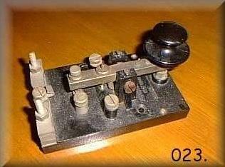
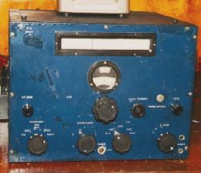
MAIN WIRELESS OFFICE - WWII ERA and POST WAR

What is known today as Radio 1 was originally called the "Main Wireless Office" during the WWII era and likely post war as well. This office would undergo at least two more major transformations before HAIDA was paid off in 1963.

1943_main_wireless_office_a.jpg
This is the layout of the Main Wireless Office at the time of HAIDA's commissioning. Port side is the top of the drawing and the right side is forward. According to Harold Dixon, a Telegraphist and part of the commissioning crew,  "there was no Coding Machine aboard. All Coding and Decoding was done by hand". At this time there is no evidence available to colloborate  that a Coding Machine was fitted in this office. (Via HMCS HAIDA Library) 

 
Jack Raine of Vancouver, British Columbia is at the controls in this self-portrait taken in HAIDA's Main Wireless Office in 1943. This starboard view looking aft shows the general arrangement on this side of the office. (Photo by Harold Dixon.  From the collection of the late Jack Raine)

 
1943rr1.jpg
This is how Jack Raine remembers Wireless Office #1. 
 
Jack also provides some operational information from 1943. "In the C/D (code/decode) area there was a black box (not shown) located under the bookcase. It was used by the POTEL for filing of confidential documents and reference material. The POTEL reported to the Signal Officer and was briefed regarding the level of secrecy prior to each operation. Telegraphists were given information only on a 'need-to-know' basis - information such as names of ships, radio call signs and frequencies. Whenever the ship was in harbour for more than 48 hours, we were required to make test calls to shore stations using one or more of the ship to shore bands. These calls were made using the 4TA or the TBL transmitters".
main_wt_office_1944a.jpg
Looking aft in 1944. By comparison to the 1946 photo, it is evident that the style of the chairs changed. The white objects surrounded by a frame are radio state boards (From the collection of the late David Fairbarns).

 
dobson.jpg
In this 1943 photo, Frank Dobson of Wolfville N.S. is tuning up the 250 watt TBL transmitter. (Photo by Harold Dixon.  From the collection of the late Jack Raine)

 
main_wireless_1943_raine_dixon.jpg
Telegraphists Jack Raine (L) and Harold Dixon (R) are at their positions in this July 1944 view which looks towards the forward bulkhead.  When compared to a similar photo taken in 1946, only the speaker in upper right had corner and the device with the three vertical meters above Jacks' right should remained in 1946. Everything else looks like it changed. (From the collection of Harold Dixon)


radio_dept_haida_1943.jpg
HAIDA's radio department circa 1943. This photo is of significance, since it indicates the crew complement in the department for the WWII era. That's Telegraphist Harold Dixon sitting on the gun barrel at the right. (From the collection of Harold Dixon)

MAIN WIRELESS OFFICE - RADIO MANIFEST IN 1944

ITEM REFERENCE  SERIAL 
NUMBER
INVENTORY 
DATE
TBL-12 HF Transmitter CAY 52248 3 January 14, 1944
60FV Transmitter 
          Absorber Unit
          Rectifier 
          Multiplier Unit 
AP 4807
AP W236
AP 4890A
AP W6260
A1054
SB23
39A
CN9
January 14, 1944
4TA Transmitter 
         Freq. Multiplier Unit 
         Generator 
         (Suspect 4TA this is part of 60FV)
AP 4807 
AP W6260
AP 1789
A1047
CN39
MT 10598
January 14, 1944
RECEIVERS [See note 1 below table]
       CDC (AC Supply)
       CDC (AC Supply)
       CDC (AC Supply)
       CDF (AC Supply) 
       CBB (Battery Supply)
       Battery Control
       Coil Box 

AP W2835A
AP W2835A
AP W2835A
AP W2698
AP 4046
AP 4707
AP 4320

MC 203535
MC 204945
MC 203500
MC 194273
PZ 353
RP 107
RA 319

January 14, 1944
TV5 Transmitter  A/P W5846 MC 216365 January 14, 1944
Type 86 VHF radio set
          Rectifier Unit 
          Motor Generator
Type 1133C 10D/388 
A/P 4208
10A/11914
3907; Being up
graded to 86M
--
July 12, 1944
Buzzer Oscillator  AP 2207 A315 July 12, 1944
B28 Receiver  AP W2835B -- July 12, 1944
Aerial Exchange Board (5/6 Receiving) AP 4036 50 July 12, 1944
FM12 MF/DF Receiver 
           FMB internal receiver

AP 5483

A361

July 12, 1944
SDO (Headache) Receiver  AP RL85 Type QD PL190 July 12, 1944
QH3 Receiver (GEE MK II Navigation
                       in Chart Room)
         Indicator 
         Power Unit 285
         RF Unit Type 24
         RF Unit Type 25
         RF Unit Type 27

R1426 Ref 101/999 
Ref 10/Q16
Ref 10K/905
10D/1015
10D/1016
10D/1054

--
845
791
11047
11896
3141
July 12, 1944
GJ Wavemeter Oufit
      with G35 oscillator,  G61 HF 
      and G62 MF wavemeters
      Two ovens 
      Rectifier.
AP 4809A
 

AP 3190 
AP 1204B

A993 July 12, 1944
Type 53 Portable Tx/Rx AP 6694A PR143 January 14, 1944
[1] CDC is an Admiralty B28 (CR100/4). CDF is an Admiralty B29 (CR200) while CBB is the Admiralty B19 which is rack mounted and part of the 60 series transmitter.


HAIDA'S RADIO EQUIPMENT - Mid 1940's

In 1993, an equipment manifest belonging to HAIDA was discovered in the National Archives of Canada. The entries relating to radio equipment were collated in the undated table shown below.
RADIO EQUIPMENT MANIFEST
(Believed to be from the mid 1940's )
QTY
FUNCT
DESIG. 
ORIGINAL
EQUIP 
DESCRIPTION
1
Loran DAS2 Loran 'A' position finding receiver
1
MF/DF FM12 MF/DF receiver; 42 to 1060 KHz
1
HF/DF FH4 HF/DF receiver; 1 to 24 MHz
1
HF/DF B28 Receiver; 60 to 420 kc; .5 to 30 Mc
1
W/T Tx TV5 Transmitter; CW / MCW / RT
1
W/T Tx TBL12  Transmitter; 175 to 600 kc; 2 to 18 MHz
1
W/T Tx 4T Frequency Multiplication Unit  100 to 17000 KHz; 
1
W/T Tx 60FR Transmitter; 100 to 17000 KHz ; CW / MCW / RT
1
W/T Tx 60EM Transmitter; 100 to 17000 KHz ; CW/MCW/RT
2
W/T Tx/Rx 53 Portable Rx/Tx; 3 to 6 MHz; battery powered.
1
W/T Tx/Rx TBS Transmitter/Receiver; 60 to 80 MHz; 50 watts
1
W/T Tx/Rx 86M Transmitter/Receiver; 100 to 156 MHz; 9 watts
1
W/T Rx B29 Receiver; 15 to 550 kHz 
7
W/T Rx B28 Receiver; 60 to 420 kc; .5 to 30 MHz
2
W/T Rx B19 Receiver; 40 to 13,500 KHz (Part of 60 series Tx ?)
LEGEND

QTY  = Quantity installed on board.
FUNCT DESIG = Functional designation as per manifest.
EQUIP = These are the model numbers as fitted.
 

MORSE CODE COMMUNICATIONS


ap7681key.jpg
This type of key or similar models would have been used aboard HAIDA during WWII. This particular example is an Admiralty Pattern No. 7681. (Photo courtesy of Meir Ben-Dror).

 
BUZZER OSCILLATOR

According to manual BR-222, buzzer oscillators were introduced into RN ships for internal signal communications. They were available in four different variants:

1) Signal Communication Buzzer outfits (vibrating buzzers)
2) Signal Communication Buzzer Outfits (vacuum tube buzzers)
3) Instructional Buzzer Outfits.
4) Remote control circuits.

With the availability of voice pipes and sound powered telephones, it is puzzling to figure out why Morse would be used for internal communication.
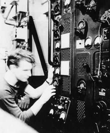
 Harold Dixon, one of HAIDA’s WWII Sparkers,  indicates the A/P 2207 buzzer was used to maintain code proficiency. 

This is is seconded by Fred Jones who served in the RN. He recalls. "In 1946 I spent a few weeks aboard HMS Tartar ,built by Swan, Hunter at Wallsend-on-Tyne. She was moored in the Devonport Naval Docks. The Wireless Office had a buzzer type oscillator and also a vacuum-tube type. They were used by the P.O. Tel., or Leading Tel., for improving the Morse capabilities of the junior ratings, when there wasn't a lot of signals traffic.  
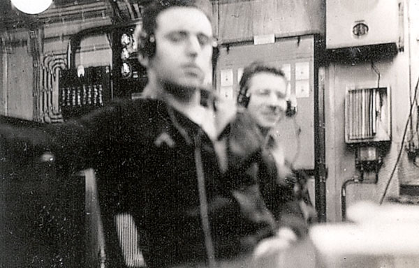
Connected to a pair of headphones, they could be used in a quiet corner of the Office, since phones  were used for all receiver outputs.  Very rarely were the loudspeakers used.  I myself used this facility to get my Morse up to 18 wpm from 12 wpm, listening in on a spare set of phones.! The buzzers were never used for communication purposes, only training".

Harold also goes on to describe Morse proficiency exercises. "We always did a little CW practice when in port in order to check the on the ability of the junior Telegraphist. Our transmitters were turned down to the lowest power setting - about 10 watts. The practice consisted of clear text of some sort usually about twenty lines long. This was followed by 5 letter groups then repeated using numbers. When all messages were copied, the Telegraphist would then send them back and from that, the Sparker was rated. The exercises were usually sent at twelve words per minute".

Harold Dixon also remembers his action station on the bridge. "I was on the bridge during all action stations and  positioned myself in a little hole just behind the glass shield .There I used a spit earphone with VHF traffic in one ear and CW in the other ear. I could operate VHF from there and optionally send the audio to a speaker. Also fitted there was a remote CW key. All orders for the alteration of ship's course came by CW from the group leader and the execute order was sent as a long dash.

Haida and other ships of the 10th Destroyer Flotilla departed Plymouth just about every night around six o'clock
to patrol the French coast. As we approached the French coast, our orders would arrive if there was any German activity observed from the French side. These were coded numeric messages for the most part. There was very little plain text. Harry DeWolf preferred to have operators on the bridge who could copy 20 wpm versus the 12 wpm requirement of the Signals School.

When destroyers were leaving on convoy or any other duty, the command destroyer would contact each ship by CW as a signal check. We were instructed to reduce power on the transmitters as low as we could make it - usually around 10 watts.

When in port there was a daily CW proficiency session directly aimed at the junior operators. Shore radio would sent out groups of numbers and also clear text. After they finished transmissions, the operator composed a similar type message and would send it back to shore radio. The shore station would then provide a proficiency report back to Capt. Harry DeWolf "

Coders, who encrypted plain text messages and decoded enciphered messages, messed together on the same deck. While on duty and when they weren't at action stations, the Coders had their own room for coding and decoding messages. When a radio operator received a ciphered message, he would bring the to the Coding Office for further processing. The only time the Coders were in the Main radio office was during actions stations. By being there, messages could be decoded much quicker before being sent up to the bridge".

Aboard HAIDA,  a Coders Office has never been located so it's presumed that the Coding functtion was intergral with the Main Wireless Office.

clock1_07071348.jpg
This is an a genuine clock made by Smith and Day. It was fitted in the forepeak and it is assumed that other areas of the ship would have been fitted with the same type of clock.  (Photo by Jerry Proc) 
.
1946 PHOTOS
1946_main_wt_office_1749_61.jpg
1946 -Starboard view of the Main Wireless office. The Marconi (UK)  FM-12 MF/DF set is at the left. In evidence are British Admiralty B-28 and B-29  receivers. There was only one typewriter in the office. (RCN photo #1749-61)
1946_main_wt_office3_1749_62.jpg
1946 - Aft view. Right foreground is a cupboard with the Westinghouse TBL and Admiralty 4TA transmitters behind it. Next to the voice pipe is a Hallicrafters HT-11 HF radiotelephone. (RCN photo #1749-62)
1946_main_wt_office4_1749_63.jpg
1946 - Aft view featuring the Westinghouse TBL transmitter. The "Man Aloft" sign has been hung. In the background is the Admiralty 4TA transmitter (RCN Photo #1749-63)
1946_main_wt_office1_1749_60.jpg
1946 - Forward Bulkhead. Power supply and distribution boards for 230 volt, 50 cycle AC. Total capacity of this outfit was 5 KVA. (RCN photo # 1749-60)
1946_main wtoffice5_1749_64.jpg
1946 - Port Bulkhead. Fitted on the middle and top shelf of the rack is the TBS-7 transmitter/ receiver. The bottom shelf contains the 86M (SCR-522) VHF transmitter/receiver. Somewhere in  there is a battery charging board for the 86M radio, and AC distribution board. On the forward bulkhead (right side), was the TBS speaker and DC Distribution Board. (RCN photo #1749-64)
The RCN  photos in the this table were provided from the collection of the late John Rouey of Ottawa, a former Electrical Officer. 


Contributors and Credits:

1) Harold Dixon <n9hoh(at)juno.com>
2) Fred Jones <g2ivsenoj2(at)talktalk.net>
3) Manual BR-222 , first published in 1932.
4) Meir Ben-Dror  <wf2u(at)ws19ops.com>
5) John Roue, Ottawa (deceased)
6) Unlucky Lady, The Life and Death of HMCS Athabaskan by Len Burrow/Emile Beaudoin. Canada's Wing's Inc. 1982.
7) Library and Archives Canada file 7400-DDE215-V1 provided by Robert Langille <ewcs(at)ewcs.ca>
8) Jim Brewer <snack.235(at)sympatico.ca>
9) John Wise <jaceywise(at)apple15.freeserve.co.uk>

Back to Table of Contents
Aug 5/16