RADIO ROOM 1 DESCRIPTION - 1957/1962 FITTING
1.1 - MAIN AREA
LOCATION: After of the upper mess deck, port passageway.
YEAR OF INSTALLATION : 1943. Modified in 1950, 1957 and 1962. Restored
in 1985. Enhancements to
the basic restoration continue as of Oct 1992.
CREW COMPLEMENT: 5 radio operators plus a watchkeeper
Staffing could consist of the following ranks:
P1RM - Petty Officer 1st Class Radioman
Dayman P2 - (did not stand watches. He would be a Petty Officer 2nd
class)
LSRM - Leading Seaman Radioman
ABRM - Able Seaman Radioman
Watchkeepers 3 OS - Ordinary Seamen
PURPOSE OF THIS ROOM: It was the main receiving and transmitting office
for the ship. It had LF (receive-only) , HF, VHF, UHF receive and transmit
capabilities.
TELEPHONE CONNECTIONS: Telephone D23 connects with Radio 4, the OPS
room and the bridge.
HISTORY:
1957
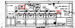 |
1957: Radio 1 as it appeared in 1957.
It is very close to the 1962 configuration. Two notable differences are:
1) The RAK receiver was moved from atop the operators console and
placed on its own shelf. It was used to guard the international distress
frequency of 500 KHz. 2) The FR12 xmtr-rcvr was sitting atop a stand on
the operators desk. Later, it was moved to its own shelf. Click on image
to enlarge (HAIDA archives drawing) |
1962
 |
| June 2007: Starboard side view of Radio 1 looking forward.
Click on image to enlarge. (Photo by Jerry Proc) |
 |
| June 2007: Port side view of Radio 1 looking aft. Click on image
to enlarge. (Photo by Jerry Proc) |
1962
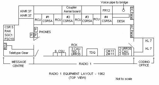 |
| 1962 Equipment Layout Diagram of Radio 1 - Top view.. The Desk was
the Message Filing Area. (Graphic redrawn by Jim Brewer) |
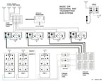 |
This pictorial illustrates the entire CW system
aboard HAIDA. Not counting the FR12, three HF CW circuits could be flashed
up if ever required. The two CW circuits in Radio 2 were remotely controlled
from Radio 1. Click on image to enlarge. Select
this link for a PDF version of the file. (Image drawn by Jerry
Proc) |
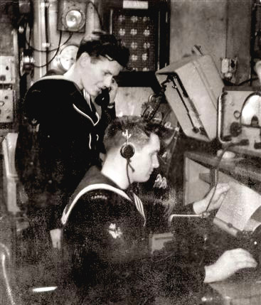 |
| Stew Patterson (standing) and ABRM Colin Blackburn at one of Morse
consoles around 1962. (Photo via Colin Blackburn) |
STAFFING
Although there were four operating positions in Radio 1, the
normal complement was one or two positions. According to Al Goodwin, HAIDA's
POTEL in the early 1960's, " I don't recall having all four positions filled.
If we had a new radioman on copying the broadcast, I might have someone
else double up with him until he got the drift of the job.
During a fleet exercise there were possibly three on watch. Once the
ship departed port we would operate around the clock, usually in
three watches. I had approximately six Leading Seamen and below ,
a PO2 and myself (PO1). I did not stand a watch".
DESCRIPTION OF EQUIPMENT
1.1.1 - Aerial Exchange Board
This was a matrix board composed of a grouping of SO-239 RF connectors
which permitted the interconnection of different receiving antennas to
the various receivers located in Radio 1. There are four antennas connected
to the coax connectors in the Y axis on the very left of the board. Each
of these connectors has additional parallel connections in the X axis.
At the bottom of the board, there are six connectors which attach to the
various receivers. Antennas were attached to receivers using one foot long
patch cords. The antennas connected to the Aerial Exchange Board were only
used for receiving.
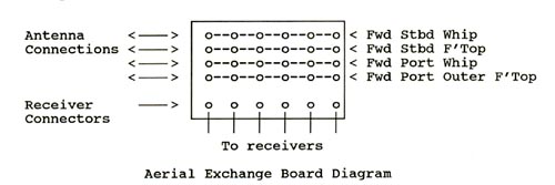 |
| Aerial Exchange Board Diagram |
Why were there two receiving whip antennas installed? The first
reason would be redundancy - in case of damage. Secondarily, the radio
operators discovered that by having two whip antennas to choose from, it
gave them the ability to select the antenna which provided the best quality
of reception.
Sometimes, it was case where one whip would simply receive a little
better than the other so the better of the two would be selected. The overall
antenna architecture aboard ship was to have all of the high frequency
receiving antennas mounted forward and all transmitting antennas mounted
aft in order to provide maximum separation. HAIDA's four whip antennas
were painted white up to the first knuckle joint and black for the remainder.
The original reasoning for this may be obscure but logic dictates that
the lower part was white to conform to an overall colour scheme which dictated
that masts, derricks, etc., would be white. The upper part was black because
the antennas were exposed to funnel smoke and got very dirty. On a black
surface, the dirt wasn't as conspicuous.
Flattop (wire) antennas were rigged to a pulley system that was used
to raise and lower them. Very often when the ship was "dressed" the
lines from the foremast carrying the lights or flags or pennants interfered
with the flattops and so they had to be lowered out of the way.
 |
This is a detailed view of the forward port whip
sponson aboard HAIDA . The ship was fitted with four 35 foot whip
antennas when she was in service. For unknown reasons, the two aft whips
were removed by the navy when HAIDA paid off. Eventually, 28 foot whip
antennas from paid off HMCS Mackenzie were located and installed on the
ship. Click on image to enlarge. (Photo by Jerry Proc) |
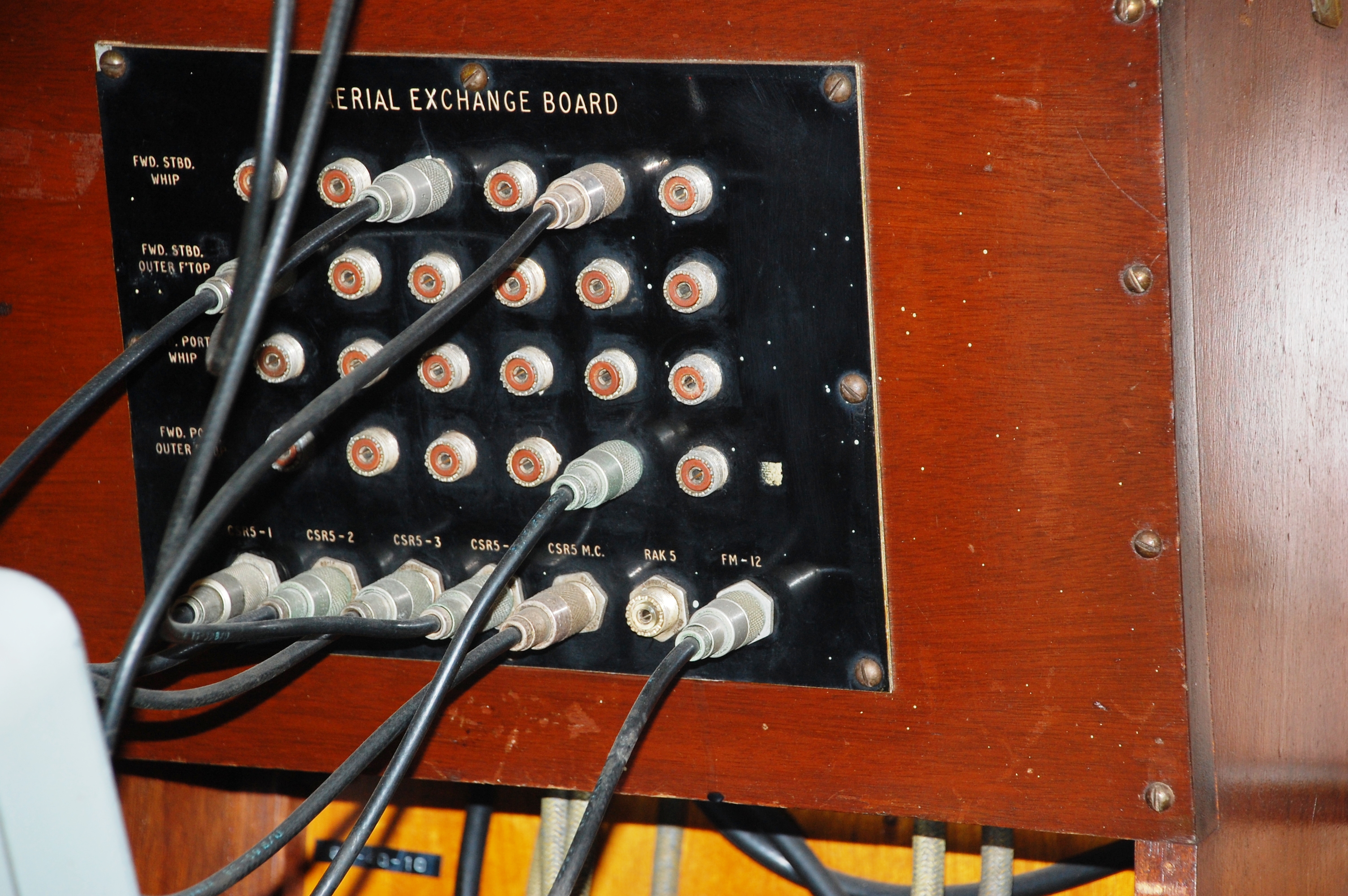 |
| Horizontally speaking, each row of SO-239
connectors are daisychained. Each row is connected to one of four antennas.
. (Photo by Jerry,Proc) |
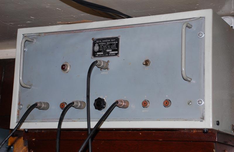
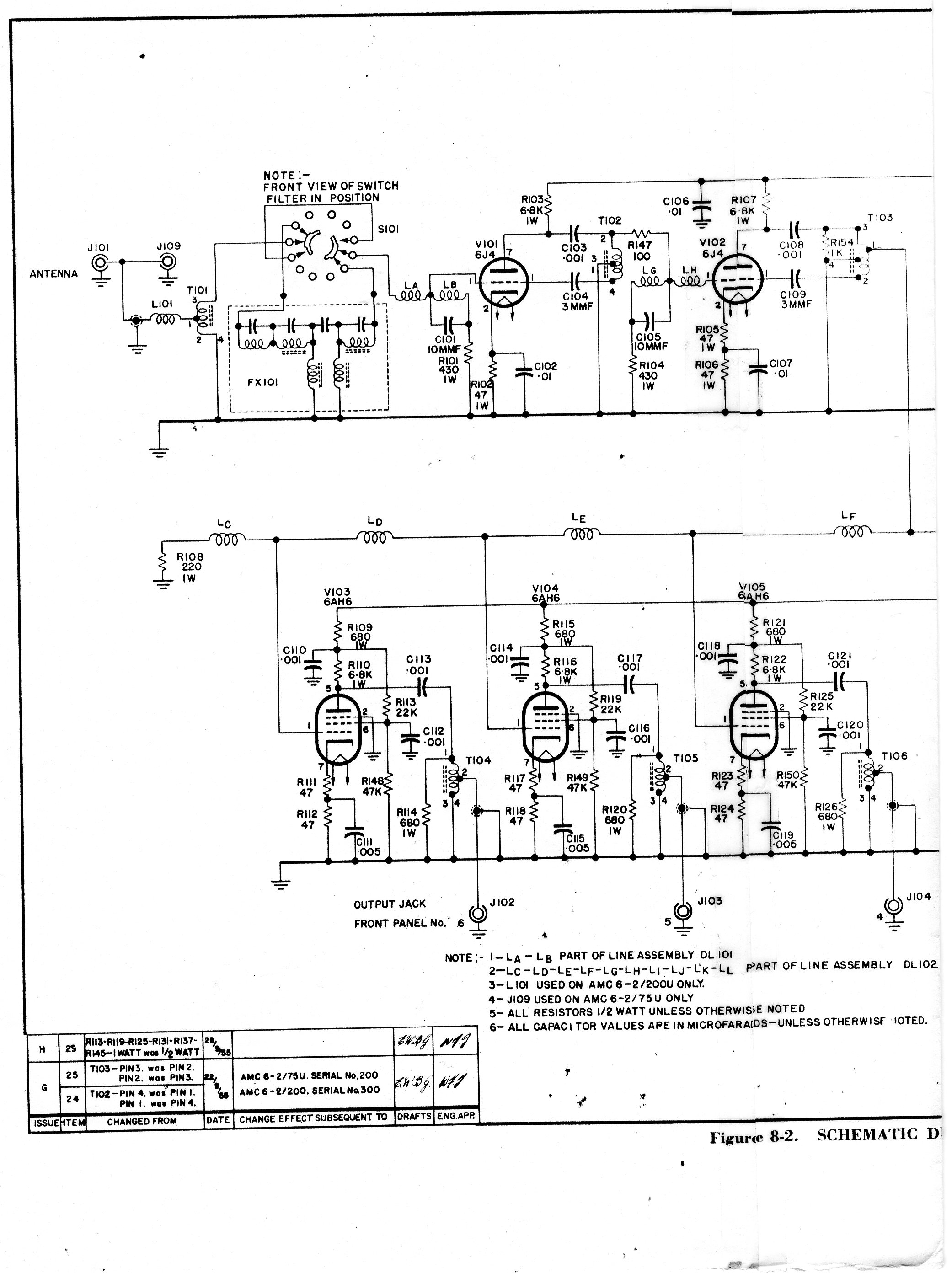
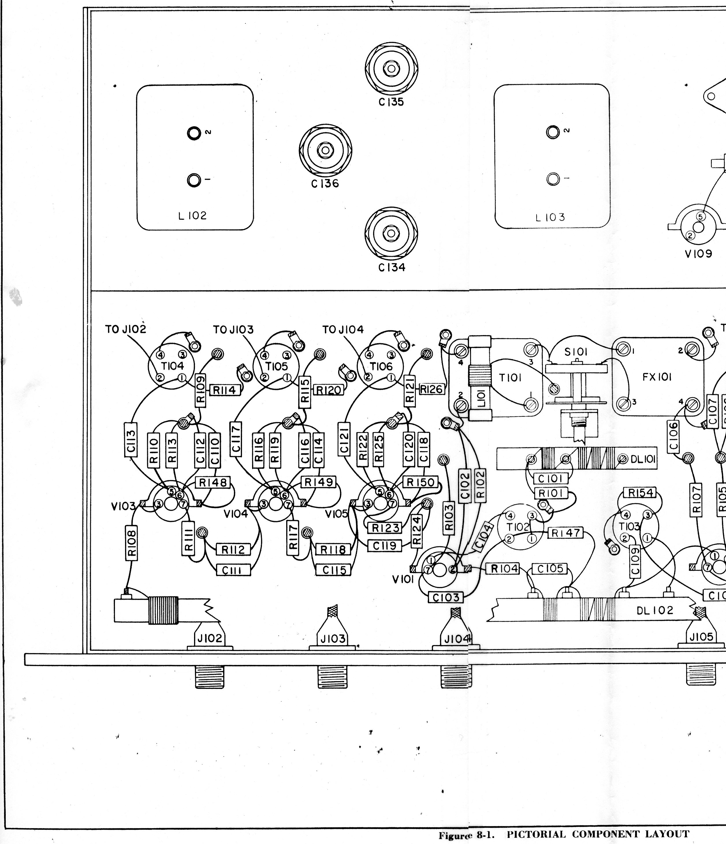
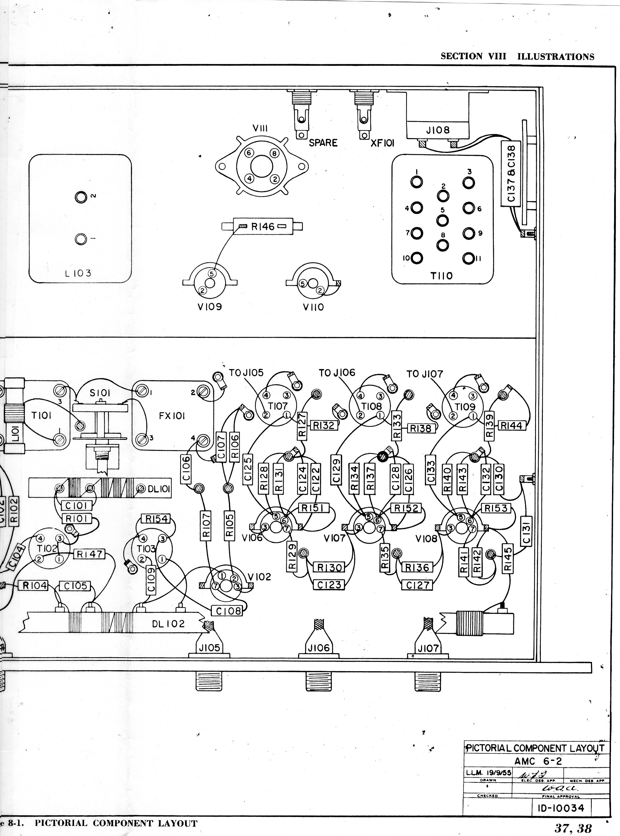
| 1.1.2 - AMC-6-2 Antenna Multicoupler
 As the requirement for additional radio channels grew during the 1950's,
it was important that each ship had separate receivers operating on many
different frequencies. Space had to found for all of the their respective
antennas so as to avoid mutual interference or interference from the ships
radar. One solution to this problem was the installation of an antenna
multicoupler.
As the requirement for additional radio channels grew during the 1950's,
it was important that each ship had separate receivers operating on many
different frequencies. Space had to found for all of the their respective
antennas so as to avoid mutual interference or interference from the ships
radar. One solution to this problem was the installation of an antenna
multicoupler.
Manufactured by TMC Limited (Ottawa) in 1953, this device is a broadband
RF amplifier which allowed a common antenna to drive up to six different
receivers in the range between 2 and 30 Mc. A switchable filter would provide
35 db attenuation against interference from signals below 1.5 Mc and each
output port provides 10 db gain when the filter is switched in. The unit
currently installed on HAIDA is not the original T164D type but it's authentic
enough for display purposes. (Photo by Jerry Proc)
|
1.1.3 - AN/URR35A Receiver
 |
This was a double conversion, UHF, superheterodyne
receiver designed to receive AM or Modulated CW (MCW) signals in the 225
to 400 Mc band. The first intermediate frequency (IF) stages operate at
18.6 Mc while the second IF functions at 1.775 Mc. URR35's were always
slaved to the same TED3 transmitter, as the transmitter contains the antenna
changeover relay. Click on image to enlarge. (Photo by Jerry Proc) |
Receiver tuning was normally crystal controlled, however, a capacitor
could be used in lieu of a crystal under emergency conditions. To tune
the receiver under crystal control, the main tuning control was coarsely
set to match the frequency of the crystal. The tuning control would be
swept back and forth and left and locked in the position where the loudest
background noise was heard. There were four variations in the URR35 receiver
family:
URR35 and URR35A - Same except for minor changes in the value of two
resistors.
URR35B - This variant was fitted with a new blower and a plug/jack connector
in order to facilitate replacement. The value of the IF Gain control was
increased to provide better control.
URR35C - In this version, the scanning circuit and the SCAN connector
on the low pass filter were eliminated along with test cables included
with previous equipment. A few resistor values were also changed. All parts
were interchangeable with previous versions except for the low pass filter
assembly at the rear of the unit. There is no evidence at this time to
suggest that the RCN used the B or C variants.
AN/URR-504 was the designator applied to the receivers sold to the RCN
and made by Cossor Canada.
These receivers were of robust design both mechanically and electrically.
They had a tube count of twenty two and weighed 57 pounds.
The following standard RCN crystal frequencies
were available for the AN/URR-35 receiver.
|
| 1.1.4 - Channel Amplifier Unit - CAU
 A bi-directional amplifier and control unit which amplified a remote audio
source and fed this to the audio input of a transmitter. In addition, it
would amplify audio output from a receiver and then feed it to a remote
location on the ship. CAU's were always used in conjunction with Channel
Switching Units and Remote Control Units. The model number of the CAU installed
on HAIDA is AM-5143/URA-501V(A). These are solid state (integrated circuit)
units which incorporate voice compression and were directly interchangeable
with the vacuum tube versions that were originally fitted on HAIDA.
A bi-directional amplifier and control unit which amplified a remote audio
source and fed this to the audio input of a transmitter. In addition, it
would amplify audio output from a receiver and then feed it to a remote
location on the ship. CAU's were always used in conjunction with Channel
Switching Units and Remote Control Units. The model number of the CAU installed
on HAIDA is AM-5143/URA-501V(A). These are solid state (integrated circuit)
units which incorporate voice compression and were directly interchangeable
with the vacuum tube versions that were originally fitted on HAIDA.
As originally designed, the CAU connects to a 32 post terminal board
located behind the unit and HAIDA is fitted with this terminal board system.
In later installations, the terminal board was replaced with a bulkhead
mounted, Amphenol Series 26 connector. As the CAU was slid into it's operating
position, the male connector on the CAU chassis would mate with the female
connector mounted on the bulkhead plate. When the CAU was withdrawn on
its runners for maintenance, a patching cord would be used to provide a
connection between the CAU and the rest of the system.
There was one internal CAU setting which needed to be changed and was
dependent upon the type of radio connecting to that CAU. Plug P511 is inserted
into socket S511 when the CAU is used with a LF/HF gear. This action causes
the audio input to be attenuated to the same level as that from a VHF/UHF
receiver. This same plug is inserted into S512 when the CAU is used with
VHF/UHF equipment. The audio to the transmitter was boosted by 10 db, while
the audio from the receiver was amplified by 30 db. When CAU's were attached
to CW or RATT transmitters, keying speeds were limited to 100 cps due to
cable length. (Photo by Jerry Proc) |
1.1.5 - Channel Switching Unit - CSU
 |
| Informally, the CSU was known as the "Bread Slicer"
and was the heart of the Shipborne Radio Remote Control System. This device
allows up to ten different Remote Control Units to be switched or shared
between five different transmitter/receiver pairs. By moving a slide switch,
any RCU could be connected to any available radio channel. Once a slide
switch was set to a particular position, the RCU could only communicate
with one transmitter/receiver pair. Click on image to enlarge. (Photo
by Jerry Proc) |
 |
| This is one of the CSU's in the swung down position.
There are 10 complex wafers in each of the six CSUs . Click on image to
enlarge. (Photo by John Paszkat) |
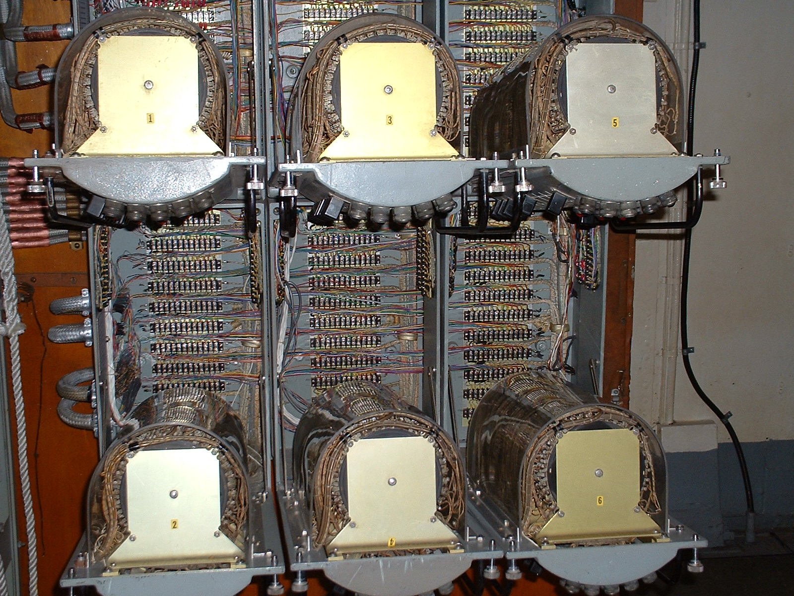 |
| This is how it looks with the six CSU's in the
open position. Click on image to enlarge. (Photo by Jerry Proc) |
The number of RCU connections or radio channel connections
to the CSU could be expanded through the use of an intermediate cable harness.
If more than ten RCU connections are required, a vertical intermediate
cable harness can be installed in order to daisy chain vertically adjacent
CSU's. This would allow additional RCU's to be shared with five radio channels.
Similarly, the installation of a horizontal intermediate harness could
be used to increase the number of available radio channels.
Mounted across the top of the CSU's are green and red lamps. Each green/red
pair provides channel status. RED means 'ready for transmission' while
GREEN indicates that the channel is 'transmitting'.
Another component of the remote control system was the Receiver Switching
Unit (RSU). This unit provided a means of switching any one of six receivers
to any one of five radio channels. When fitted, there could only be one
RSU for the whole system. RSU's were not used on HAIDA and are only mentioned
here for the sake of completeness. The CSU/RCU/CAU remote control system
was a Canadian development that worked very well and was admired by our
contemporaries in the Royal Navy and the United States Navy. All of the
radio remote control system was manufactured by Beaconing Optical and Precision
Materials Company (BOP) in Granby, Quebec. (Photo by Jerry Proc)
There are a total of fourteen RCUs connected to the CSUs. RCU's
1, 2, and 3 are on the Bridge. Units 4, 5, 6, 7 and 8 are in the Ops Room.
No. 9 is in the Message Centre. Nos 10, 11, 12 and 13 are in Radio
1 and lastly, No. 14 is in Radio 4. The Bridge and Ops Room are fitted
with four channel RCUs with the remainder being single channel units. Some
of the RCU are hardwired together. The following labelling appears on the
front of the CSUs:
9, 10, 11, 12, 13, 14
178-1, 17-2, 17-3, 17-4
26-1, 26-2, 26-3, 26-4,
345-1, 35-2, 35-3, 35-4
Here is a decode for two of the designations.
Example #1 178-1 means Channel 1 of RCUs 1, 7 and
8 are hardwired together.
Example #2 345-1 means that Channel 1 of RCUs 3,
4, and 5 are hardwired together.
Using slide switches on the CSU, any radio channel of interest can be
connected to single channel RCUs or the hardwired combinations on
the four channel RCUs.
 |
Here, Jerry Proc (L) and Jim Brewer (R) are restoring
HAIDAs Radio RemoteCcontrol systen as featured in The Canadian Amateur
Magazine in Febryary 1996. It woul be a project that spammed
nime months of Saturdays to complete.
When HAIDA paid off, the navy severed all the cables which terminated
on the Channel Switching Units and the Remote Control Units. This was dome
to expedite the removal of the equipment. To get the system operational
again, it took some 4,000 wire splices and connections. The
best part was that it all worked when the system was flashed up. Click
on image to enlarge. (Photo courtesy Radio Ammeters of Canada) |
| 1.1.6 - CM11 Transmitter/Receiver
 First built in 1942, the CM11 was a transmitter/receiver that was capable
of operation in the 375 kc to 13.5 Mc range. There were two distinct bands
of operation: 375 to 515 kc on low frequency and 1.5 to 13.5 Mc on high
frequency. In the high frequency band, the CM11 could be used with crystal
or master oscillator frequency control. For low band operation, only the
master oscillator could be used. The RCN labelled CM11 crystals with two
additional frequencies besides the fundamental - the second harmonic and
the third harmonic. The transmitter could be tuned to operate on any of
the three frequencies. Modes and power levels were: CW - 100 watts; MCW
- 70 watts; AM - 30 watts. The Signal Electric R63 was the key provided
with the CM11 - RCN pattern number 3M/103.
First built in 1942, the CM11 was a transmitter/receiver that was capable
of operation in the 375 kc to 13.5 Mc range. There were two distinct bands
of operation: 375 to 515 kc on low frequency and 1.5 to 13.5 Mc on high
frequency. In the high frequency band, the CM11 could be used with crystal
or master oscillator frequency control. For low band operation, only the
master oscillator could be used. The RCN labelled CM11 crystals with two
additional frequencies besides the fundamental - the second harmonic and
the third harmonic. The transmitter could be tuned to operate on any of
the three frequencies. Modes and power levels were: CW - 100 watts; MCW
- 70 watts; AM - 30 watts. The Signal Electric R63 was the key provided
with the CM11 - RCN pattern number 3M/103.
Inter-connection between the transmitter, receiver and antenna tuner
was provided by snatch plugs. These connectors operate on the same principle
as knife switches. Each of the three slide out units in the CM11 are equipped
with female snatch plugs. When slid into place, the antenna tuner, transmitter
and receiver interconnect through a wiring bus that is fitted with male
snatch plugs. When withdrawn for maintenance, patch cords had to be installed
between the transmitter or receiver and the bus. The CM11 antenna tuner
was a very versatile device, since it could match antennas that were 5
to 750 ohms resistive and supported operation in the range of 375 kc to
13.8 Mc.
The following standard RCN crystal
frequencies were available for the CM11 transmitter.
Keith Kennedy ex-C2NET(s) of Surrey BC notes that "the CM11 was notorious
for generating harmonics and spurious emissions and HMC Ships would routinely
receive harmful interference reports from the Department of Transport monitoring
station located at Wetawaskin Alberta. We had little in the way of test
equipment and certainly nothing as fancy as a spectrum analyzer so we just
followed the CM11 tuning instructions and filed the reports away. The CM11
was also known for its chirpy CW signal when controlled by the master oscillator
but it behaved properly under crystal control. CM11's also had a bad habit
becoming detuned as the ship rolled. It was the result of changing capacitance
between the antenna and the surface of the sea".
Gerry Taylor was a former RCN radio operator. He recalls his experiences
with the CM11 transmitter.
"My memory of the use of the CM-11 is pretty well limited to a only
a couple of ships that I served in. I mainly used it for sending and receiving
but I did have to know how to tune them up for the desired output
mode and frequency. I preferred to use it mostly on CW 100
watt output. The transmitter that we used the most for Navy Traffic
at sea was the PV500, which had a much higher wattage output.
The ship that I used the CM-11 on the most was HMCS Fort Erie,
in 1962. On that ship, we were on a three month cruise up and down
the West Coast of Africa, from Dakar Senegal to Lagos Nigeria. There
were two ships on that Cruise - the Fort Erie and the New Waterford.
We were supporting three Canadian Trade Fairs up and down the Coast. The
ship was licensed for ham radio, and the call sign was VE0NR. Not
a lot of military stuff going on during this cruise, and the CM-11 met
the legal limits for ham radio operation. A few times
we were able to connect with Ontario stations who made phone patches for
us to family members.
As I recall, the quality of the CM11's phone mode was not that
great. The reliability of the set seemed to be good. I can't remember
having any technical issues occurring during use. I liked the
tone of the CM-11 on CW output. On Modulated CW output, you got a
totally different tone as I recall. They clunked and made a lot of
noise. I cannot recall using anything other than the Master Oscillator
on the CM-11. The Main Radio Room had about 3 or four work stations
in a row. We would use one of the work station receivers to listen
to the CW conversation..
On HAIDA's bridge, a SM11 remote radio telephone control unit can still
be seen. It was abandoned after the RCU/CSU/CAU radio remote control system
was installed. All of the CM11's fitted on HAIDA were connected to the
Shipborne Remote Control System and were keyed or controlled by the RCU's.
The power supply for the CM11 was very versatile, as it could operate
on 120/220 VAC or 24/36/220 VDC power sources. A fifteen second time delay
circuit prevented power from being applied to the transmitter in order
to protect the mercury vapour rectifiers. There was an emergency mode which
decreased the time delay to 4 seconds but at the expense of shorter mercury
rectifier life. Weighing in around 478 pounds, the CM11 just wasn't portable!
Eventually, the CM11 was superseded by the AN/URC32 transceiver. (Photo
by Jerry Proc)
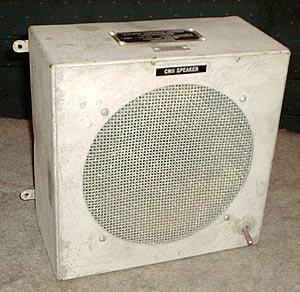 |
| CM11 speaker. (Image source unknown) |
|
| 1.1.7 - CPRC-26 Transceiver
 Designed by the Canadian Signals Research and Development Establishment
and manufactured by Rogers Majestic starting in 1951, this was the first
Canadian developed and built post World War II military radio.
Designed by the Canadian Signals Research and Development Establishment
and manufactured by Rogers Majestic starting in 1951, this was the first
Canadian developed and built post World War II military radio.
The CPRC-26 was a self-contained, battery operated, transceiver (walkie
talkie) which operated in the frequency range of 47.0 to 55.4 Mc. Its 300
milliwatt input is frequency modulated using a deviation of +/- 15 KHz.
Six, crystal controlled channels were available for communication. Power
was provided by a dry battery and a fresh unit would provide about 20 hours
of service. Normally, the CPRC-26 would be used with a 47 inch collapsible
whip antenna. It was a unique set for its time since it had replaceable
modules.
All RCN ships carried three CPRC-26 transceivers which were usually
kept in the main radio office. A communicator would carry one in a lifeboat
and with landing or boarding parties. Other uses included short term communication
between ships for such jobs as jack-stay transfers, underway fuelling and
shoots. It was an excellent means of communication between the bridge and
the emergency conning position during times of crisis. In total, there
were around 4,500 of these units built for NATO forces by Philips and Canadian
Rogers. By 1969, the RCN declared this gear as obsolete, dangerous or unreliable
depending on the source of information.
The following standard crystal frequencies
were available for the CPRC-26 :
Select this link for photos of the CPRC-26. |
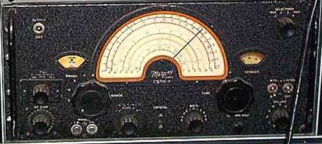
| 1.1.8 - CSR 5A Receiver
 First built by Canadian Marconi in 1942, this general coverage receiver
was capable of receiving AM and CW signals between 80 kc and 30 Mc with
the exception of the broadcast band. It had a tube count of thirteen and
weighed in at sixty eight pounds without power supply. CSR 5A's spent most
of their working life receiving the Fleet Broadcast or guarding the International
or marine distress frequencies. Each receiver was connected to its own
wall mounted speaker, but headphones were the order of the day. Loudspeakers
were used when one Radioman had to guard more than one frequency. This
was known as a loudspeaker watch.
First built by Canadian Marconi in 1942, this general coverage receiver
was capable of receiving AM and CW signals between 80 kc and 30 Mc with
the exception of the broadcast band. It had a tube count of thirteen and
weighed in at sixty eight pounds without power supply. CSR 5A's spent most
of their working life receiving the Fleet Broadcast or guarding the International
or marine distress frequencies. Each receiver was connected to its own
wall mounted speaker, but headphones were the order of the day. Loudspeakers
were used when one Radioman had to guard more than one frequency. This
was known as a loudspeaker watch.
A modification was made to this receiver by the RCN. The "F" band (80
to 200 kc) was adjusted 10 kc low to enable the reception of the broadcast
frequency of 73.6 kc. This frequency is still assigned to Maritime Command
as of 1994. The RCN also labelled CSR- 5A crystals with two additional
frequencies besides the fundamental - the second harmonic and the third
harmonic. The receiver could be tuned to operate on the fundamental or
the other two frequencies. One of the noted quirks of the CSR 5A was the
habit of going off frequency in rough weather when continuous tuning was
used. If a large wave hit the ship, it would overcome the friction of the
tuning gear assembly and knock the dial off frequency. There were no such
things as frequency synthesizers or phase locked loops in those days. The
vernier control would be used to retune the frequency.
In the CSR 5A, the band-switch assembly has been wired into a sub-chassis
which can be detached from the main chassis. This operation should be never
be attempted by the inexperienced. First, you extract the receiver from
its case and detach the bottom cover plates - do not be concerned over
the 30 screws that secure the plates. Next, desolder 29 connections as
outlined in the manual. Following that, there are another 20 screws to
remove in order to physically detach the RF turret. Do not go insane in
the process, or you won't be able to get the pieces back together. This
brief glimpse of 1942 radio maintenance has been presented for those readers
who have complaints about 1990's manufacturing methodology. (Photo by
Jerry Proc)
 Much rarer, is the Marconi CSR5Y, a variant adapted for diversity reception.
Rather than having a toggle switch for the AVC, a three position rotary
switch is used. It is marked DIV, OFF and INT. The Send/Rcv switch is eliminated
since the receiver is intended to be in receive mode all the time. There
is also a terminal strip on the rear of the chassis marked AVC. The AVC
was probably derived from an external comparator when in Diversity mode.
In all other respects, the Y variant is identical to its more common cousin.
The CSR5Y would mostly likely be found in a shore installation. (Photo
courtesy Meir Ben-Dror, WF2U)
Much rarer, is the Marconi CSR5Y, a variant adapted for diversity reception.
Rather than having a toggle switch for the AVC, a three position rotary
switch is used. It is marked DIV, OFF and INT. The Send/Rcv switch is eliminated
since the receiver is intended to be in receive mode all the time. There
is also a terminal strip on the rear of the chassis marked AVC. The AVC
was probably derived from an external comparator when in Diversity mode.
In all other respects, the Y variant is identical to its more common cousin.
The CSR5Y would mostly likely be found in a shore installation. (Photo
courtesy Meir Ben-Dror, WF2U)
In July of 1992, there was only one functioning CSR 5A receiver
in Radio 1. During the winter of 1992/1993, four of the receivers were
repaired, refinished in the original colour of 50 years ago and refitted
with shock absorber assemblies. One receiver in particular, had ten faults
which required correction.
The VP3 power supply for the CSR 5A was designed to operate from 120/220
volt 50/60 Hz AC power or 12 VDC. When operating on DC power, some changes
had to be made. Marconi designed two power interlocks to ensure that no
damage could be caused by inadvertent operation on the wrong power source.
To switch from AC to DC operation, a five pin interlock plug had to be
moved from one socket to another. Subsequently, the AC line cord had to
be disconnected from the wall socket and inserted into a special chassis
mounted receptacle. VP3 power supplies also acquired a reputation for fusing
the contacts on the vibrator and frying the primary winding on the power
transformer. By 1969, the CSR 5A was considered obsolete and was taken
out of service.
In July of 1992, there was only one VP3 supply among four CSR 5A receivers.
Another VP3 was found in storage but was completely deteriorated and had
to be rebuilt from bare metal. Since three other VP3 power supplies were
missing, near replicas were constructed in order to restore operation to
the receivers.
The following standard RCN crystal
frequencies were available for the CSR5 receiver.
|
| 1.1.10 - RCK Receiver - AN/URR21
 Weighing in at 117 lbs, the RCK was a 'low radiation' VHF receiver built
by E.H. Scott Radio Laboratories during the 1940's. Copious use of RF shielding
helped contribute to its hefty weight. The RCK had four crystal controlled
channels and operated in conjunction with the TDQ transmitter in the 110
to 160 Mc radio band. Also, there were nine sockets for storing additional
crystals.
Weighing in at 117 lbs, the RCK was a 'low radiation' VHF receiver built
by E.H. Scott Radio Laboratories during the 1940's. Copious use of RF shielding
helped contribute to its hefty weight. The RCK had four crystal controlled
channels and operated in conjunction with the TDQ transmitter in the 110
to 160 Mc radio band. Also, there were nine sockets for storing additional
crystals.
One unusual feature of the design was the tuning system. Normally, when
a receiver is under crystal control, the main tuning dial must be set to
the same frequency as the crystal. This is accomplished by sweeping the
dial back and forth across the operating frequency until the loudest background
noise is produced. In the RCK, there was a mechanical tuning mechanism
that could be preset so the main tuning dial hits a 'detent' position at
the exact frequency of operation. When this happened, a red channel indicator
light came on to show the channel number being received. If any of the
crystals were changed, and you wanted the use of the 'lamp on frequency'
feature, then a mechanical tuning assembly would have to be re-adjusted
with an internally mounted Allen key.
The RCK manual of 1944, lists a number of standard VHF frequencies for
which crystals were available.
Frequencies (in Mcs) listed are as follows:
116.10 117.90 119.34 121.50 123.66 124.02 124.38
126.18 128.70 140.58 140.76 140.94 141.12 142.02
142.56 142.74 143.28 143.64 144.00 144.36 146.16 147.96
149.49 151.20
The following standard RCN crystal frequencies
were available for the RCK receiver. (Photo by Jerry Proc) |
In summary, HAIDA's VHF system is comprisesd of
a four channel RCK receiver paired up with a 45 watt TDQ transmitter and
a Channel Amplifier Unit. The transmitter is connected to a
vertical dipole on the end of the 'H' shaped yatdarm, foremast.
It was missing so a replica antenna was fabricated when HAIDA
was in Toronto. Arrangements were made with the Toronto Fire Department
to install the antenna. Over the years, the wind has managed to bend the
antenna elements out of shape in spite of using ¼ inch steel rod
in its construction.
| 1.1.9 - FR12-TH Transmitter/Receiver
 Made by Canadian Marconi in the early 1940's the FR12 was a three mode
transceiver - CW, MCW and radio telephone. Power input was 15 watts on
CW, less on MCW and even less on phone. It was capable of transmitting
on low wave (375 to 580 kc) or short wave (1700 to 4200 kc) depending on
the model type. On low wave, the set had a range of about 20 miles. On
receive, it was capable of continuous tuning from 300 to 4200 kc. The letter
H in the model number indicates that the remote control option was installed,
however, it was not compatible with HAIDA's Radio Remote Control System
and was not used.
Made by Canadian Marconi in the early 1940's the FR12 was a three mode
transceiver - CW, MCW and radio telephone. Power input was 15 watts on
CW, less on MCW and even less on phone. It was capable of transmitting
on low wave (375 to 580 kc) or short wave (1700 to 4200 kc) depending on
the model type. On low wave, the set had a range of about 20 miles. On
receive, it was capable of continuous tuning from 300 to 4200 kc. The letter
H in the model number indicates that the remote control option was installed,
however, it was not compatible with HAIDA's Radio Remote Control System
and was not used.
The following standard RCN crystal frequencies
were available for the FR12 transmitter/receiver.(High frequency)
The following standard RCN crystal
frequencies were available for the FR12 transmitter/receiver.(Low frequency)
Under normal use, the FR12 would be used to communicate with merchant
ships or the Naval Administrative Net. Pictures taken in the 1950's show
the handset installed, so it was definitely used on voice. Emergency communications
could be provided by this unit if all else failed since it only operated
from a 12 volt DC power source. The receiver section consisted of a five
tube superheterodyne design with the ability to continuously tune the range
of 300 to 4200 kc in three bands. To simplify the overall design, there
was no direct frequency readout for the receiver. Instead, a circular logging
scale dial was provided. It was necessary to calibrate the dial, and record
the readings in advance.
In the transmitter section, there was an oscillator, a modulator and
a dual power output stage. One of four, selectable, internally mounted
crystals determined the operating frequency. In order to activate the modulator,
one simply inserted the handset plug into the front panel socket. The microphone
in the handset provided the interlock for the modulator. If this was done
while the Dynamotor was running, a noticeable slow down of the Dynamotor
could be heard.
Power for the FR12 could be provided by one of two modes. In standby
mode, the filament circuit for the transmitting tubes gets disabled. Filament
power for the receiver would be provided from the main battery. The 180
volt B+ line for the receiver would be furnished from four, external, 45
volt dry batteries wired in series. Standby mode would dramatically increase
the life of the main battery. In normal mode, all power for the receiver
and transmitter was provided by the main battery. An internal Dynamotor
produced high tension for the transmitter but it had to be inspected after
every 500 hours of operation. Input power to the FR12 was 12 volts DC at
6 amps on receive and 13 amps on transmit when used in normal mode. On
HAIDA, the antenna for the FR12 was a sloping, twenty seven foot vertical
wire designated as the PORT OUTER VERTICAL.
Al Goodwin of Dartmouth N.S. did some range experiments with the FR12.
"It was sent away in a sea boat on a couple of occasions. In those days,
we didn't have commercial mobile antennas available to us, so we rigged
up a 35 foot whip antenna. The exercise was not deemed a success as we
lost communications around five miles. On HAIDA, we used this set for both
AM and CW communications. For CW operation, we would have to attach a key
with a very long lead. In an unusual case, the late Keith Lake (VE1PX)
used the FR12 to modulate the Marconi PV500 thus giving it AM capability
for use on the amateur bands. He put out quite a strong signal compared
to the 30 watts of the Marconi CM11". (Photo by Jerry Proc) |
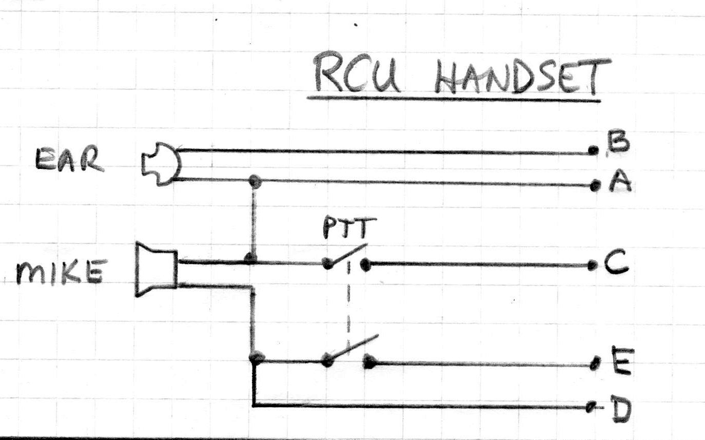
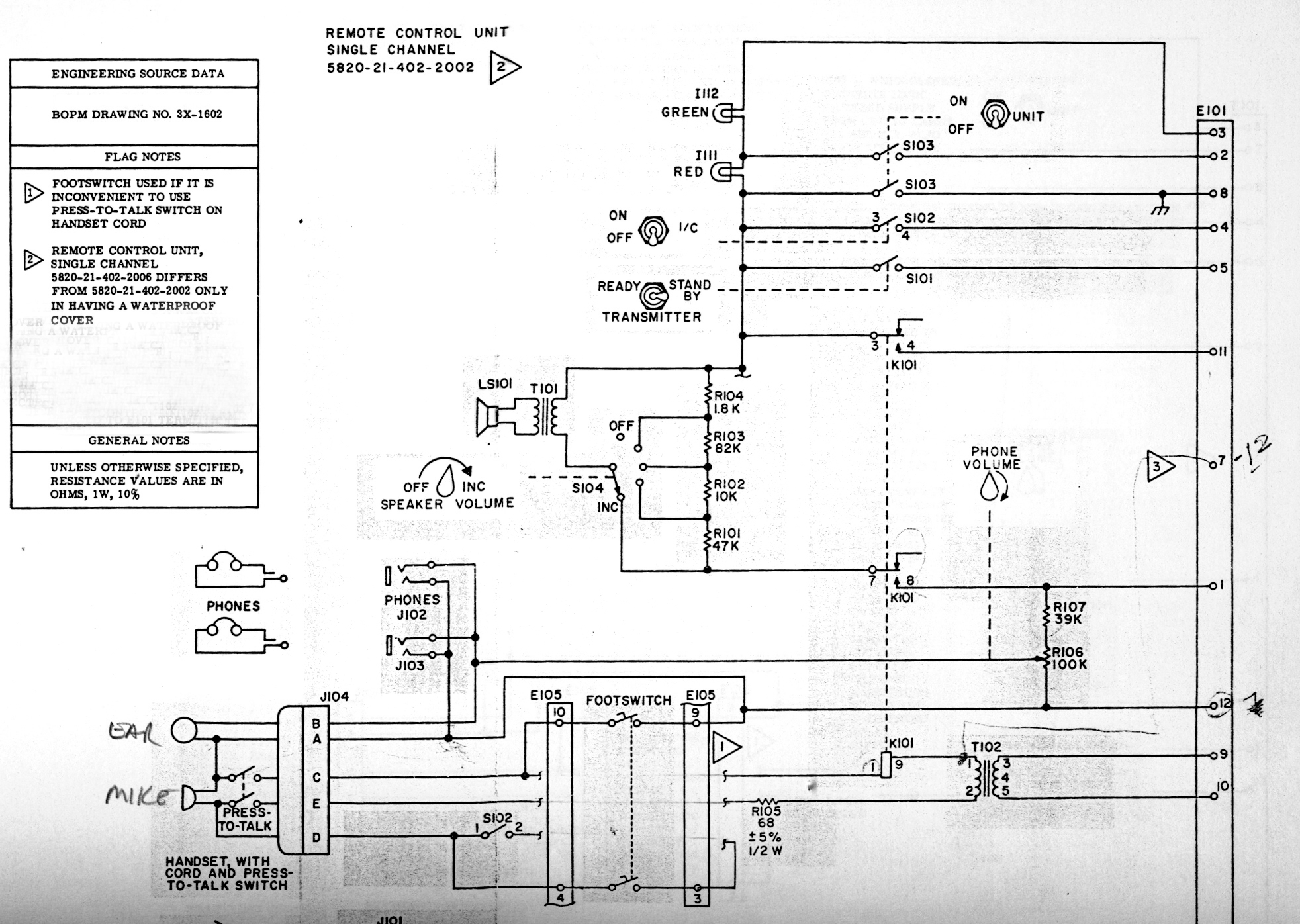
1.1.11 - Remote Control Unit (RCU)

|
 |
| RCU with clamshell closed up. |
RCU with clamshell open. |
| This was a device that allowed a radio channel to be controlled
from a remote location on the ship. RCU's come in single channel and four
channel versions, with and without weatherproof covers. A single channel
unit only had the capability of controlling one radio channel, while the
four channel unit could switch between, and control, up to four radio channels.
An RCU supported both voice and CW operation and provided the functions
of an intercom.
The RCU also keys the transmitter via the Channel Amplifier when sending
Morse code. . The maximum Morse speed is 100 characters per second depending
on cable length from the RCU to the transmitter. .
Every system has limitations, so the Radiomen had to observe some operating
precautions. In normal operation, the manufacturer suggested that a maximum
for four RCU's be connected to any given radio channel. Intercom functions
were limited to those RCU's connected to the same radio channel. It was
also possible to connect more than one RCU to a radio channel. Despite
these minor restrictions, the system worked very well. (Photo by Jerry
Proc)
A wiring diagram for the RCU handset can
be found here,
RCU schematic is here. |
 |
| This RCU to CSU interconnect diagram shows
the locations of the RCUs. Select
this link for a PDF version of the file. (Drawn by Jerry Proc) |
| 1.1.12 - TDQ Transmitter
 First built for the U.S. Navy in May of 1943, this unit was capable of
voice or MCW transmissions in the 115 to 156 Mc band running 45 watts continuous
power. Any one of four selectable crystals determined the frequency of
operation. The following standard RCN crystal
frequencies were available for the TDQ transmitter.
First built for the U.S. Navy in May of 1943, this unit was capable of
voice or MCW transmissions in the 115 to 156 Mc band running 45 watts continuous
power. Any one of four selectable crystals determined the frequency of
operation. The following standard RCN crystal
frequencies were available for the TDQ transmitter.
Before the days of UHF equipment, destroyers were fitted with a pair
of TDQ/RCK sets. These were used for operations circuits such as "Plot
Primary". When the RCN followed the United States Navy to UHF voice, the
TDQ/RCK was left behind as the only VHF set capable of monitoring and communicating
with aircraft, other ships, yachts and harbour facilities. The basic role
for this set became that of 'guard' for the VHF distress frequency of 121.5
MHz. The TDQ could be remotely operated through the shipborne radio remote
control system. Weighing in at 285 pounds, it was extremely heavy by today's
standards. (Photo by Jerry Proc) |
 |
| VHF System Diagram. Select
this link for a PDF version of this drawing. (Drawn by Jerry Proc) |
| 1.1.13 - TED3 (AN/URT-502) Transmitter
 The TED3 was a low power UHF transmitter capable of AM or MCW operation
in the 225 to 400 Mc band. TED transmitters were designated as AN/URT-502A
by the RCN and were built by Westinghouse in Hamilton Ontario and the RCA
Victor Company, Montreal. Nevada Air Products and RCA Victor produced URT502B's.
Each TED3 in Radio 1 was connected to a separate, weatherproof, UHF dipole
antenna located on the lower yardarm of the foremast. The designated model
number for the antenna is AT-150/SRC. TED3's were introduced into service
in 1952.
The TED3 was a low power UHF transmitter capable of AM or MCW operation
in the 225 to 400 Mc band. TED transmitters were designated as AN/URT-502A
by the RCN and were built by Westinghouse in Hamilton Ontario and the RCA
Victor Company, Montreal. Nevada Air Products and RCA Victor produced URT502B's.
Each TED3 in Radio 1 was connected to a separate, weatherproof, UHF dipole
antenna located on the lower yardarm of the foremast. The designated model
number for the antenna is AT-150/SRC. TED3's were introduced into service
in 1952.
A TED3 was always used in conjunction with a Channel Amplifier Unit
and a URR35 receiver. This combination of equipment provided a "UHF communications
channel". Radio 1 provided three out of the seven UHF communication channels
aboard HAIDA, while Radio 3 provided the other four. Surprisingly, TED's
were routinely used in MCW mode on the intership Task Group Common circuit.
TED's had small, axial crystals which fit into a four position crystal
holder located behind a hinged door. Radiomen had to carry out frequency
shifting drills which consisted of quickly changing the whole set and it
could become very frustrating if a crystal was dropped. It would invariably
disappear under an equipment rack and would never roll back out!
The following standard RCN crystal frequencies
were
available for the TED3 (AN/URT-502) transmitter. Frequencies
marked with an asteriskare for use by the CNEL. (Canadian Navy Electrical
Laboratories) |
1.1.14 - Frequency Measuring Equipment
 |
| BC221 photo courtesy RCN. |
BC-221
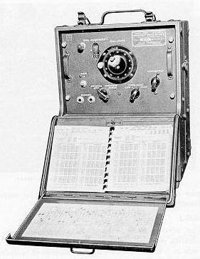
The BC221-M Frequency Meter was designed to provide a means of accurately
calibrating transmitting and receiving equipment within the frequency range
of 125 kc to 20 Mc where no crystal was available for a radio channel.
This meter is a portable heterodyne type with a built in crystal calibrator.
A unique calibration book was prepared for each unit and it could not be
interchanged with other BC221 meters. Power was provided by a dual voltage
dry battery.
AN/URM-32
Eventually the BC221-M was superseded by the AN/URM 32 Frequency Meter.
This unit was used to calibrate transmitters in the frequency range of
125 kHz to 1000 MHz when crystals were not available. Unlike the older
BC221, the URM 32 could be powered from 120 VAC or batteries. In addition
to its use as a frequency meter, this unit also had the capabilities of
a signal generator.
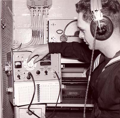 |
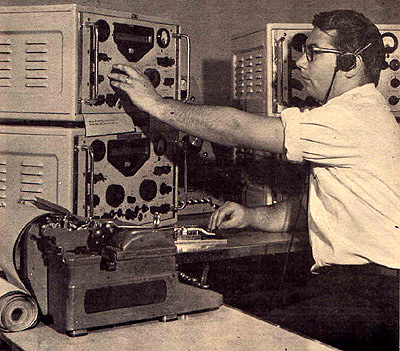
| Dave Blais, RCN radioman at the time, adjusts the URM-32 frequency
meter aboard HMCS Restigouche in 1959. (RCN photo from the collection
of Dave Blais) |
Click on photo to enlarge
|
MORE RADIO 1 PHOTOS
|
 |
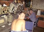
Forward view in March 1961: LSSG Harold
Stratton has a chokehold on Ronald Yaschuk (foreground). At the left of
the photo is the the bulkhead partition which was extended in 1962 to enclose
the Message Center. It must have been very noisy back then with the Teletype
machines chattering away and without sound isolation. (Photo submitted
by Ronald Yaschuk e-mail: ronlynn(at)rogers.com) |
 |
A starboard/forward view in 1960: This
entire area was reconfigured when the navy fitted crypto equipment aboard
the fleet in 1962. The rack at the back was the radioteletype (RATT) bay
and looks very similar to the way it does today. The big black box on the
starboard bulkhead was the LF receiver used to copy the broadcast to submarines.
(Photo
by Ronald Yaschuk) |
 |
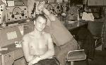
A starboard/aft view in 1960: ABRM Ron
Stebner. He passed away in 1971 at age 27. (Photo by Ronald Yaschuk) |
 |
A starboard/aft view in 1960: ABRM Ron
Stebner and LSSG Harold Stratton in a lighter moment. There were
additional modifications made to this corner after 1960. The Marconi FR12
transmitter receiver (barely visible) was moved to its own shelf, affixed
to the starboard bulkhead and a storage area was fitted to the top-rear
of the desk. Note the stateboad affixed to the power panel. (Photo
by Ronald Yaschuk) |
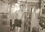 |
Aft view in March, 1961: ABRM Ron
Stebner poses next to the Marconi CM11. The section of the room remained
unchanged until HAIDA paid off. (Photo by Ronald Yaschuk) |
OTHER EQUIPMENT
AID Speaker
Radio 1 is fitted with one AID speaker and fitted to it's right is a
boom mounted, AID microphone. The 1962 drawing does not show a microphone
fitted, so this one remains a mystery.
Amateur Radio
Al Goodwin of Dartmouth N.S., served aboard HAIDA as the POTEL (senior
radio operator) from May of 1960 until she was paid off in October of 1963.
Al recollects some memories from this period. "I operated the amateur radio
station from early 1962 when I first received my ticket until we paid her
off. At one time, we had five operators working the bands and that was
probably a record number for one ship. For a receiver, I removed the Hammarlund
SP600 in Radio 4 and used it with either a Marconi CM11 or PV500 transmitter.
A VE0 call was very rare in those days and one CQ brought back a 'pileup'.
One thing still sticks out from this period. The CO thought that operating
an amateur station was really neat. He used to bring his guests into Radio
1 and show them the QSL cards that were displayed on the aft side of the
message centre bulkhead. One day, he noticed a QSL card from Russia and
asked - 'What would you talk to him about?' I replied 'Crypto codes - of
course', a remark that I passed during the height of the Cold War".
Clocks
AC power to the radio room was notoriously unstable and the cyclic
output of the alternators was even worse. This prevented the use of electric
clocks whose synchronous motors depended on precise regulation of the frequency
of the input power. Although marginally better, Seth Thomas mechanical
clocks were used, but they too were somewhat erratic. These clocks had
to be set to time stations WWV or WWVH daily.
With reference to radio room clocks marked with the red silent periods
for 500 kHz distress ( as above), some ships did have clocks with the markings
while others did not. Some also included the black silent periods for 2182
kHz AM distress on the hour and half hour. These markings were not universal
and in some cases the clocks had no silent period markings at all. Fred
Ware , a WWII era Telegraphist could not recall a single ship that he served
in where the radio room was fitted with a clock with the silent periods.
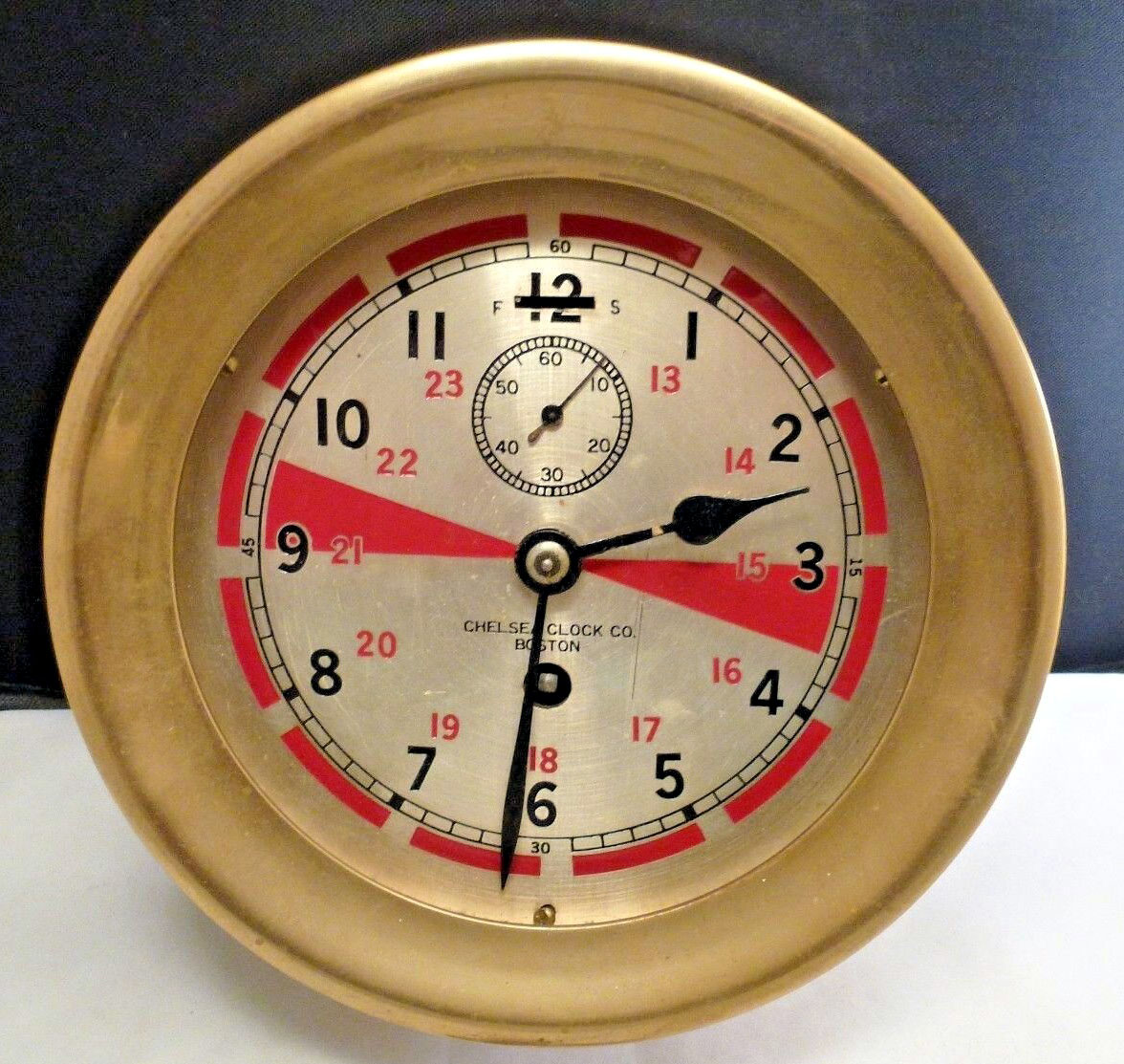 |
| This is a typical example of saship's radio room clock before
1947. In that year, 2182 KHz was added to become the International
voce distress frequency, so "green" three minute silent periods were
added at the hour and half hour intervals. Wedges could also be found
in red/green, red/blue (Scandinavia) and red/pink (USSR) colours.
(Photo via E-bay).
Those red bars are 4 seconds long and are separated by spaces of 1 second
in length to assist the radio operator in sending an automatic alarm signal
by using a hand key if the automatic key failed to work. |
 |
| This radio room clock (?/) sports a Roman numeral face. There
are two red lines to denote the 500 KHz silent periods. It is not known
if these are original or if they were added by some radio operator. Sestral
of England built this clock for HMS Chatham and one of the
distributors was "R.F. BOVEY -VANCOUVER B.C." (Photo and copy
via E-bay) |
CLOCK SPECS
These were the specifications for a ship's radio room clock as dictated
by Maritime law.
80.828 Radiotelegraph Station Clock.
A working clock equipped with a sweep seconds hand and having a dial
not less than 12.7 cm (5 inches) in diameter, the face of which is marked
to indicate the silence periods prescribed for the radiotelegraph service
by the International Radio Regulations, must be provided. It must be securely
mounted in the radiotelegraph operating room in such a position that the
entire dial can be clearly observed by the radio officer from the normal
radiotelegraph operating position, from the operating position where the
international radiotelegraph alarm signal would ordinarily be transmitted
by hand, and from the position used for testing the auto alarm (if installed).
If a separate emergency radiotelegraph operating room is provided, the
requirements of this section apply to it also.
[51 FR 31213, Sept. 2, 1986, as amended at 58 FR 44953, Aug. 25, 1993]
 |
If anyone wishes to create their own radio room
clock, this PDF file might be suitable. The face is 4.5 inches in diameter.
Click on the graphic to launch the file.The drawing can be scaled with
software such as Inkscape for any size. The pdf file contains vector
art not bitmap art which means that the clock face can be scaled for any
size from a watch face to an outdoor clock face.
For 500 KHz., silent periods were always a quarter and a quarter
after the hour for a 3 minute duration. For 2181 KHz, it for 3 minutes
past the hour and half hour. The silent periods can be marked in different
colours depending on the manufacturer of the clock. (Drawn By David
Ring Jr. N1EA) |
COAX CABLE
With the exception of CM11#3 in Radio 2, all the CM11s and UHF
transmitter/receivers are connected to their respective antennas with RG-18
coax cable. RG-18 is about 1 inch overall diameter. The centre conductor
is solid copper, about 1/8 inch in diameter. Surrounding it is the dielectric
and the electrical braid. The coax itself is covered with a protective
braid to resist damage from shrapnel. RG-18A/U has an impedance of
52 ohms and has been replaced by RG-219/U whose voltage rating is 11 KV.
Crystal Cabinet
The crystal cabinet, mounted above the TDQ transmitter, was used to
store all of the crystals that would be required to fulfil any Communications
Plan. Keith Kennedy of Surrey B.C recollects details about the cabinet.
"Physically, the cabinet was of wood or aluminum construction, and was
as wide as the TDQ transmitter and two thirds of its height. When the ship
was in harbour, the front doors were secured with a bar and combination
lock. Internally, there were six to eight slide out plywood shelves or
trays with numerous felt lined pockets approximately two inches square.
Each pocket contained two crystals - one for service and one was a backup.
The transmitter and receiver crystals were kept on separate shelves to
prevent them from getting mixed up. For the most part, the cabinet was
used to store crystals for TED/URR type equipment, but some CM11 transmitter
and CSR5 receiver crystals were also stored here ".
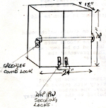 |
The crystal cabinet aboard HAIDA is missing.
Radioman Keith Kennrdy provides this sketch of how it looked physically
and the approximate dimensions. The section of the bulkhead where the cabinet
was mounted has not discloured at the same rate as the remainder of the
bulkhead. The lack of discoloration thus provides for the actual
width and height dimensions of the cabinet. If a replica cabinet were to
be built, the dimensions of the non faded area would need to be followed.
Click on image to enlarge. If anyone with woodworking skills wants to build
a replacement cabinet, contact : Jerry.Proc@sympatico.ca |
CW Keys
Two types of straight keys were used for CW transmission. One was the
Speed-x square, chrome based type. The other was the tear- drop shaped,
black wrinkle finish base variety. Keys were mounted on a clear plastic
plate which straddled a rectangular hole located in a bay, at the right
side of the operating desk. Electrical connections were made to the KEY
input of the Remote Control Units next to the CSR 5A receivers. In HAIDA's
case, it's suspected that the keys were hardwired into the RCU.
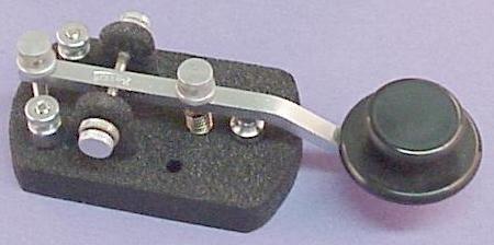 |
| This key is the Speed-X Model 320-001 made by the E.F. Johnson Company
and was used by the RCN during the 1950's and 1960's. The example in the
photo was made in 1967 and the RCN part number was 114-320. (Photo courtesy
of Morse Express ) |
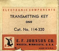 |
| This is the box end for the above key. (Image courtesy Spud Roscoe) |
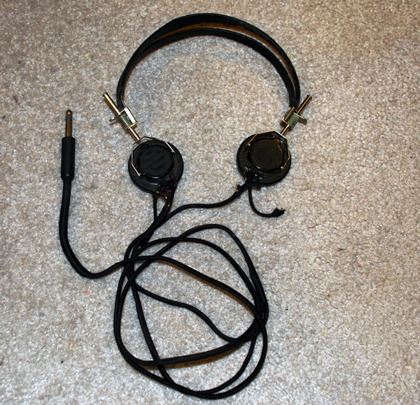
Headphones
Headphones that were in general use in the 1950' had bakelite earpieces
cushioned by soft rubber coated pads. The two spring bands connecting the
two earpieces was covered with stitched, tan coloured leather Each
headphone assembly bore two markings: MX- 41/AR and ANB-H-1. It is not
known who manufactured these two specific models. By the 1962, the RCN
switched over to headphones made by the TRIMM company. These did not have
earpiece cushions.
 |
| These Headphones, made by TRIMM, were in use
by the RCN in 1962 and would have been used specifically aboard HMCS HAIDA.
(Donated
by: Wayne Blenkhorn VE1BAB. Photo by Jerry Proc)
Spud Roscoe adds: "We did not wear the TRIMM headphones over the ears.
Rather, they were placed on the head just slightly forward of the ears
and because we were also copying fast Russian operators, we kept the audio
gain up so one and all could hear it. Some had it so loud you could hear
it a mile away" |
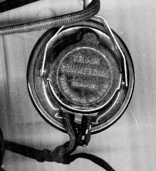 |
| Headphone markings: TRIMM Commercial
Libertyville Ill. (Photo by Jerry Proc) |
Metal Desks and Chairs
Metal desks that were used for the operating consoles were supplied
by Eaton's of Canada but it is not known whether they could be purchased
by the general public. The original colour is a metallic flake green finish
as evidenced by looking underneath some of the sliding typewriter trays.
Over the years, the desks have been repainted in the routine colour of
navy grey. On HAIDA, all of the slide out drawers in the desks are missing
the locking latches. These would be essential to have in a rough sea.
Gregory McLean of Abbotsford B.C. recalls, with great detail, the furnishings
and the some of the routines in Radio 1. "The chairs used in some radio
rooms of the 1950's were swivelling arm chairs. They were of robust construction,
with padded backs and tubular sides. The bases of these chairs were bolted
to the deck and a pivoting steel shaft was affixed to the underside of
the seat. This shaft was fitted into the base, thus giving the chair firm
support and allowing the operator to swivel 360 degrees. This type of seating
arrangement persisted in some ships and is still in use today.
To a great extent, it was felt that the swivel chair was superior to
the 'chair and chain' technique which was used on HAIDA at the time of
her de-commissioning. The tubular sides and the anchored base gave firm
support in rough seas and was easy to use. On the chained chairs, the chair
did not move once the chain was secured making it difficult to get ones
legs out from under the desk.
Decks on ships were scrubbed every day, but special house cleaning was
done for Captain's rounds. Radio 1 "scrub out" was in the middle or morning
watch when the radio traffic volume was least. At that time, the swivel
chairs were pulled from their bases and set to one side. The 'broadcast'
chair was left to last in case traffic resumed".
When seamen were not on radio watch, spare hours were filled with maintenance,
book amendments, cleaning stations and working part ship (painting, scraping
etc).
 |
| 1950s and 1960s: These were the style of chairs that would be
found aboard Radio 1 in HMCS HAIDA What is there today came from
a post 1963 ship. In the fireground is ABRM Ron Stebner. (Photo via
Ronald Yaschuk) |
POWER
Mounted on the aft bulkhead, starboard side of Radio 1, is the DC power
distribution panel for the equipment in the room which was capable of operation
from a DC power source in case of emergency. Emergency power was provided
by a large battery bank positioned in the starboard passageway aft of the
bulkhead in Radio 1. This battery could be re-charged by the ship's electrical
system.
Adjacent to the DC panel, is the wood and glass encased AC distribution
panel. AC power for the equipment in Radio 1 was supplied from here. HAIDA
was originally fitted with a 225 VDC electrical system. Power was supplied
by two 200 kilowatt generators that were steam driven and two diesel driven
60 kilowatt units. As more and more American equipment was fitted in the
ship, it became necessary to produce 120 VAC 60 Hertz power. Lead case
cable was used in Canadian ship construction post-war as evidenced in the
four Canadian-built Tribals. Probably the first use of armoured cable was
in the 3"50 gun system (including gun drives, Mk63 GFCS and AN/SPG34 radar)
installed in Tribals around 1950
 |
| The glass and wood panel at the right is the AC distribution panel
for Radio 1 and Radio 3. Feeding the panel is a 3 phase, 440 volt
Delta source which originates from the forward AC switch board in
the Electrical Workshop. The AC feed is at the lower left corner.
Power is then then distributed to the various branch circuits in
Radio 1 and Radio 3. Near the left top are two pilot lights
which indicate that the panel is live, however, only one of the lights
is visible in this view. (Photo by Jerry Proc) |
 |
| This is the low voltage DC distribution panel It distributes
emergency DC power to whatever Radio 1 equipment had the capability to
operate from a low voltage DC source. The batteries that fed this panel
were located inside an enclosure which was affixed to the deck on the the
opposite side of the bulkhead. They would be recharged from the ships 220VDC
grid, This 220 volt feed is at the top of the panel. Note that the two
voltmeter switches atop the manel are missing. Click on image to enlarge.
(Photo by Jerry Proc)
From the markings on the tally plates, it appears that one CSR-5 receiver
and the FR-12 transmitter/receiver were connected to separate 12 V batteries.
There are markings that show the CM-11 being connected to a 24 battery
, however there is no motor -alternator set for the CM-11 in Radio 1. It
is suspected that the 24 V source for the CM11 may have been provisioned
from the low power room one deck below Radio 1.All the 24 volt wires are
cut with no loose wires underneath. |
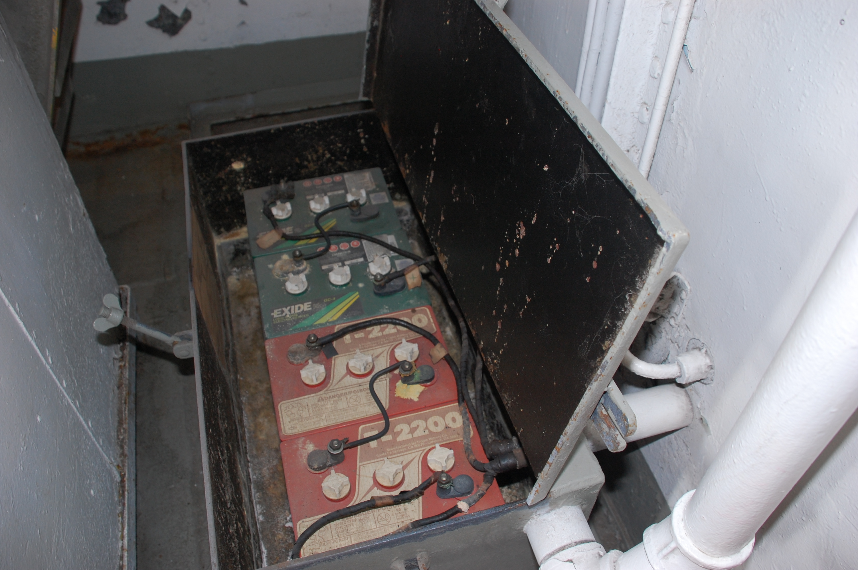 |
| The batteries which fed the low power panel in Radio 1 were situated
in this enclosure. There are four 6 volt batteries.here. Each pair is wired
in series to produce 24VDC. Click on image to enlarge,. (Photo
by Jerry Proc) |
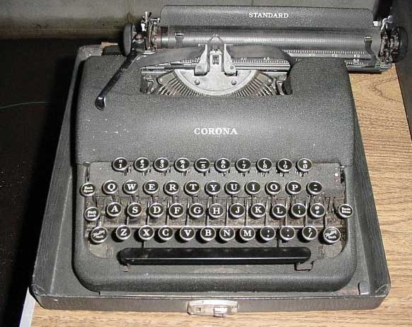
Telegraphic Typewriters
The typewriters used at the operating consoles were Royal or Remington
Telegraphic typewriters which could only print capital letters and some
special symbols. Two keys away, and to the right of the letter L was a
"dead" key which would print a line and then, without the carriage moving,
the operator could type an accented or Tiddley" (special) letter.
They were of the closed frame variety and painted in wrinkle finish
grey. The typewriter itself, was bolted to a sliding tray which was located
in the middle bay of the desk. Radiomen often referred to the typewriters
as "mills". In those days, the Royal or Remington typewriters looked sleek
and modern.
 |
| Cpl B.A. Kelly of St. John's Nfld., operates a CW position at Canadian
Force Station Mill Cove N.S. in 1970. The typewriter in the photo was typical
of those used to copy CW in that period. (Photo courtesy Maritime Command
Trident, Nov. 1970) |
Often, an operator would spend long hours in continuous copy.
In order to make life more comfortable, he would pull the pins that restrained
the typewriter tray and move the tray out and slightly down. Everything
worked fine until a large wave hit the ship and in turn, it would cause
the typewriter to jump forward and unto the operators lap, often with undesirable
results. The unfortunate operator might be talking with a slightly high
pitched voice for a while. The paper supply for the typewriters consisted
of rolls which were mounted on a separate assembly within the centre bay
of the desk. Each roll of paper had metal caps inserted into the cardboard
core. Metal caps were saved as some of the paper rolls issued by the navy
did not come supplied with these. A thin steel rod was passed through holes
punched in the metal caps. The rod was then placed into slots on an angle
iron bolted inside the middle bay. This assembly allowed the paper to unroll
easily and kept the roll stable as the ship moved about in the sea. The
paper holder assembly was not part of the original desk and was added as
the need arose.
Generally speaking, one or two ply paper rolls were used for CW copy
but usually one. Teletype circuits, particularly broadcast, used two or
three ply but usually two. When supplies of one ply paper ran short, a
three ply roll would be rewound into individual two and one ply rolls.
These techniques were used because storage space on board was always at
a premium. Having 'stores' carry multipurpose items was most desirable.
Teletype ribbons were rewound onto typewriter spools because the ribbons
supplied for teletypes lasted much longer than the typewriter ribbons that
the navy purchased.
Three copy paper was used when the ship was the designated guard ship
in the group and copying the broadcast. The main problem with custom wound
rolls was the tendency for the paper to loose alignment. During a busy
watch, the operator had to align the sheets frequently. It was both the
fault of the platen pressure and the type of paper being used. This problem
became very critical when receiving a long message and the machine could
not be stopped to fix the paper. Needless to say, using more than two ply
paper was not popular.
Fanfold paper with perforations was tried at one point, but the paper
was difficult to set at the perf line. One message might be three lines
long while the following message might be three pages long. Some Radiomen
were accustomed to tear-off rolls and would tear off the sheet at the point
where the message ended. Trying to line up the perforations before the
next message started proved somewhat difficult.
Spud Roscoe offers this comment on typewriter installations. "A typewriter
in a ship had to be mounted so that the carriage ran fore and aft. A typewriter
with the carriage athwartships was more or less useless. When the ship
rolled you had to hold on to the carriage and move it with each letter.
When the typewriter was mounted so its carriage was fore and aft, it rarely
needed assistance unless the ship was really pitching badly".
Ronald Yaschuk describes a typewriter trick used in his era. "We attached
a heavy duty rubber band (of which we had plenty) to the carriage return
handle and the other end was fastened to the side of the typewriter bay.
This tensioned the platen to the left and offset the force of gravity when
the ship pitched. It served the purpose adequately".
In an effort to improve typing efficiency, the RCN evaluated telegraphic
typewriters whose keyboard layout resembled that of a teletype machine.
HMC Ships St. Croix and Swansea were among those who were chosen to receive
the initial batch of evaluation units. It was the intent of Canavhed (Canadian
Naval HQ) to standardize the "typing skill" of the Communication Trades
into one keyboard - basically that of the Teletype keyboard.
It was also intended to introduce a type of electro-mechanical typewriter,
which would eventually supersede the existing telegraphic typewriters in
copying or transcribing morse. As typewriters became unserviceable, they
would be replaced with the improved models. However, there was no intention
to use the new typewriters in the Communications School because the presence
of an on-site Queen's Printer typewriter repair shop made it virtually
impossible for a typewriter to require replacement. Training would continue
on the current type but, when new typewriters were encountered, it would
be up to the operator to make the keyboard conversion on his own time.
The new keyboard was to look like this:
Line 1
1 2 3 4 5 6 7 8 9 0
Line 2
Q W E R T Y U I O P NR
Line 3
A S D F G H J K L GR
Line 4 (Upper) " : ;
x ? , . /- (a dashed slash)
Line 4 (Lower) Z X C
V B N M / BT
NR = Station serial number
GR = Group
BT = Long pause
Dashed slash = ?
Sea trials indicated that some of the new typewriters were not standing
up. It is assumed that this initiative to develop a common keyboard
was ultimately abandoned.
 |
| This telegraphic typewriter used by US Navy illustrates the upper
case only keyboard with the slashed zero character. (E-bay photo) |
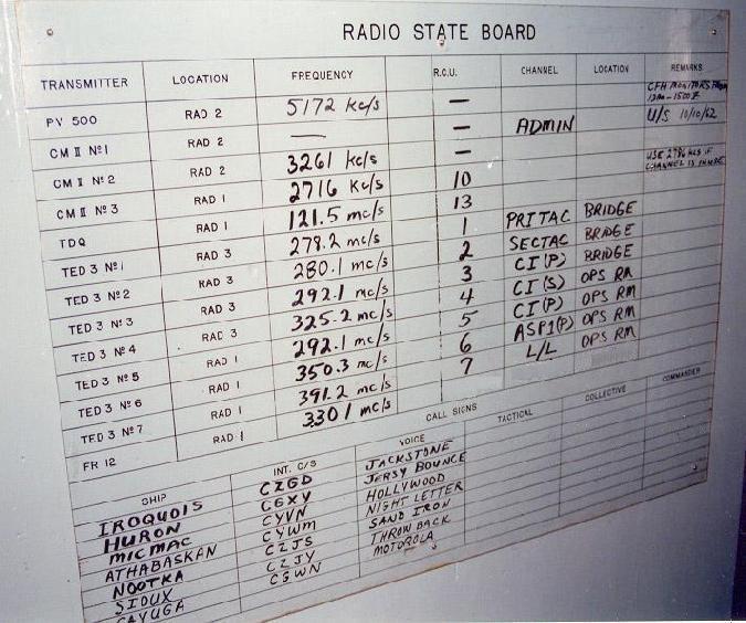
Radio Stateboard
Ron Yaschuk describes the rudimentary radio state board used in Radio
1 in 1960. "The stateboard was affixed to the front of the AC power panel
with metal clips. Templates were drawn up on white cardboard sheets which
were then sandwiched between two pieces of plexiglass. This enabled
the operators to keep track of the connections between Remote Control Units
and the radio circuits. An example of the makings would be:
Pri Tac - 273.6 MHZ - CAU# - OPS Room
Hbr Com - 283.4 MHZ - CAU# - Bridge etc., etc.
Each time a change in frequency was made or a Channel Amplifier Unit
changed position or designation, the stateboard would be wiped with paper
towel and the new designation, frequency and remarks would be updated
with grease pencil".
 |
| This is an example of a typical radio stateboard. The board has
been marked up to be as authentic as possible to an early 1960's radio
environment. The actual stateboard in HAIDA was affixed to the main
fuse panel in Radio 1 bur it didn't resemvle this example.(Photo by
Jerry Proc) |
 |
| This was the actual radio state board used
in HAIDA's Radio 1. It was attached to the AC distribution panel. |
Shielding and Woodwork
Under the panelling, Radio 1 is encased with sheet copper which becomes
visible around the door frame for the Coding Office door. The purpose
of the copper shield is to minimize radio interference that is produced
from different parts of the ship and to ensure that radio frequency interference
generated within Radio 1 does not affect sensitive equipment in other parts
of the ship.
The air duct which spans the entire length of Radio 1 is comprised of
1/4 inch plywood only. There is no metal beneath. Besides being aesthetically
pleasing, it is believed that the duct was fabricated from wood to help
reduce the noise level of the airflow.
 |
| In this example, the copper shielding peeks out on the door frame to
the Crypto office and the door itself. Radio 2 iand the Message Center
are shielded in a similar manner. Radio 3 and 4 did not need shielding
because they were surrounded by the steel in the bulkheads. |
| Sound Powered Telephones
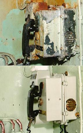 Installed throughout the ship are numerous sound powered telephones. Unlike
a regular telephone which needs 48 VDC to operate, these telephones convert
the energy of sound waves into electrical energy which powers the sets.
Installed throughout the ship are numerous sound powered telephones. Unlike
a regular telephone which needs 48 VDC to operate, these telephones convert
the energy of sound waves into electrical energy which powers the sets.
The actual efficiency of a sound powered link is about 25 db lower than
that of a regular carbon microphone system. This limits the sound powered
equipment to point-to-point applications and limited party line applications
where the line loss does not exceed 15 db. Because of the resonant characteristics
of the microphone and receiver units, the frequency response of the telephone
falls off sharply for frequencies above 2000 Hz.
There are two types of telephones installed on HAIDA. One type is the
single line set and the other type is a selectable, six line unit. To originate
a call on a single line set, the user turns the crank on the phone. This
sends a ring voltage down the line which powers a buzzer and illuminates
a neon lamp on the remote unit. The remote user than picks up the handset
and communication can be established with the use of push-to-talk switches.
Phones can be wired as party lines, so rotating the crank on one phone
makes all of the other phones ring. By using ringing codes, only a certain
phone will get answered. On a party line, the recipient of a call listens
for the correct ringing code then selects the proper line with a rotary
switch. The telephone system uses three wire, armoured cable for communication.
White is common, black is voice, and red is ring.
The photo illustrates a sound powered telephone in a badly deteriorated
state. After 6 to 8 hours labour, the phones were restored back to their
1960's condition. (Photo by Jerry Proc) |
 |
 |
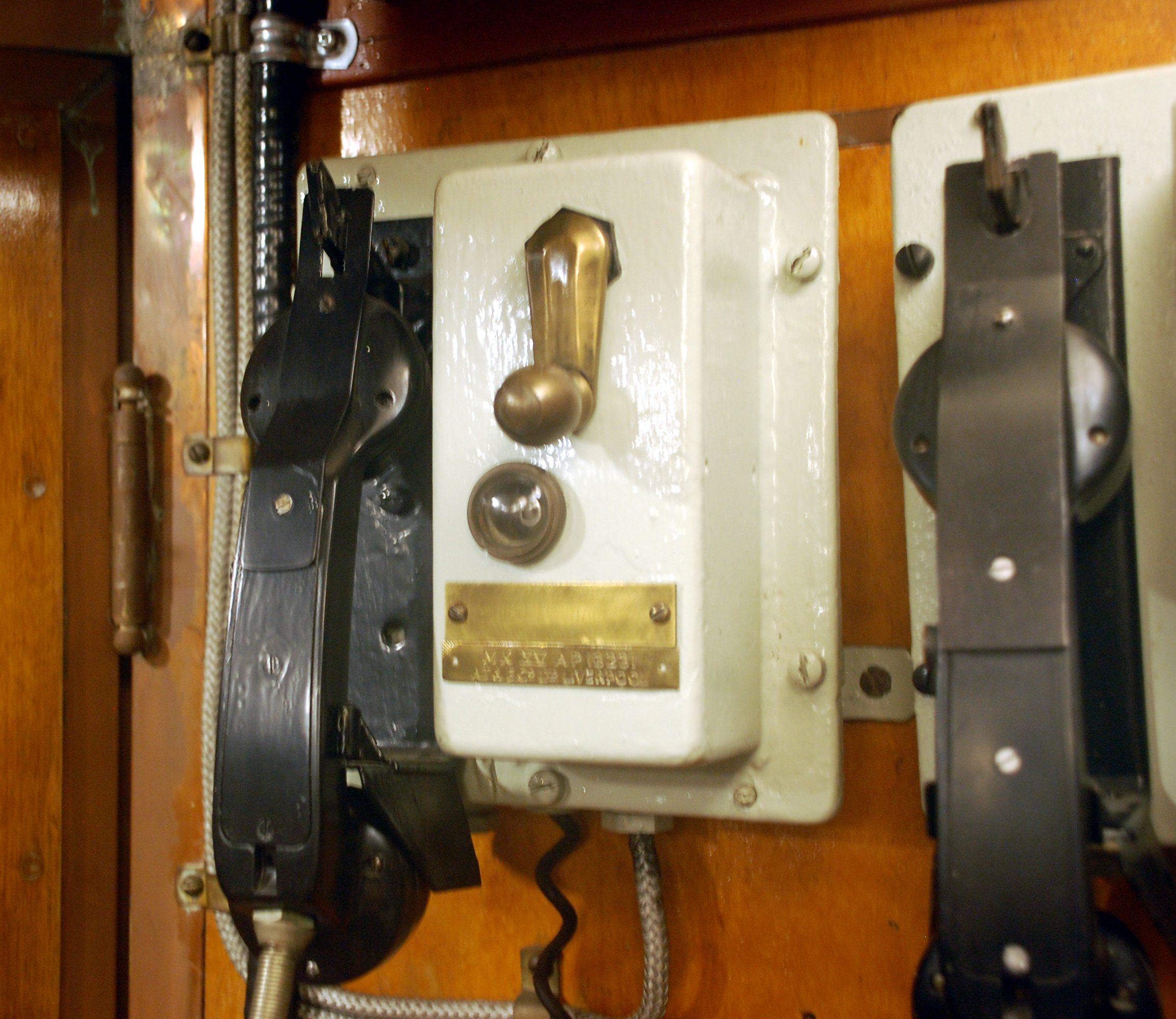
| HAIDA's original telephones were Mk XV A/P 13231
manufactured by the Telephone Mfg. Company in London England.and also AT&E
in Liberpool./ These telephones stowed the handset by using a metal strap
over a hook. This is an example of a single line phone. (Photo by Jerry
Proc) |
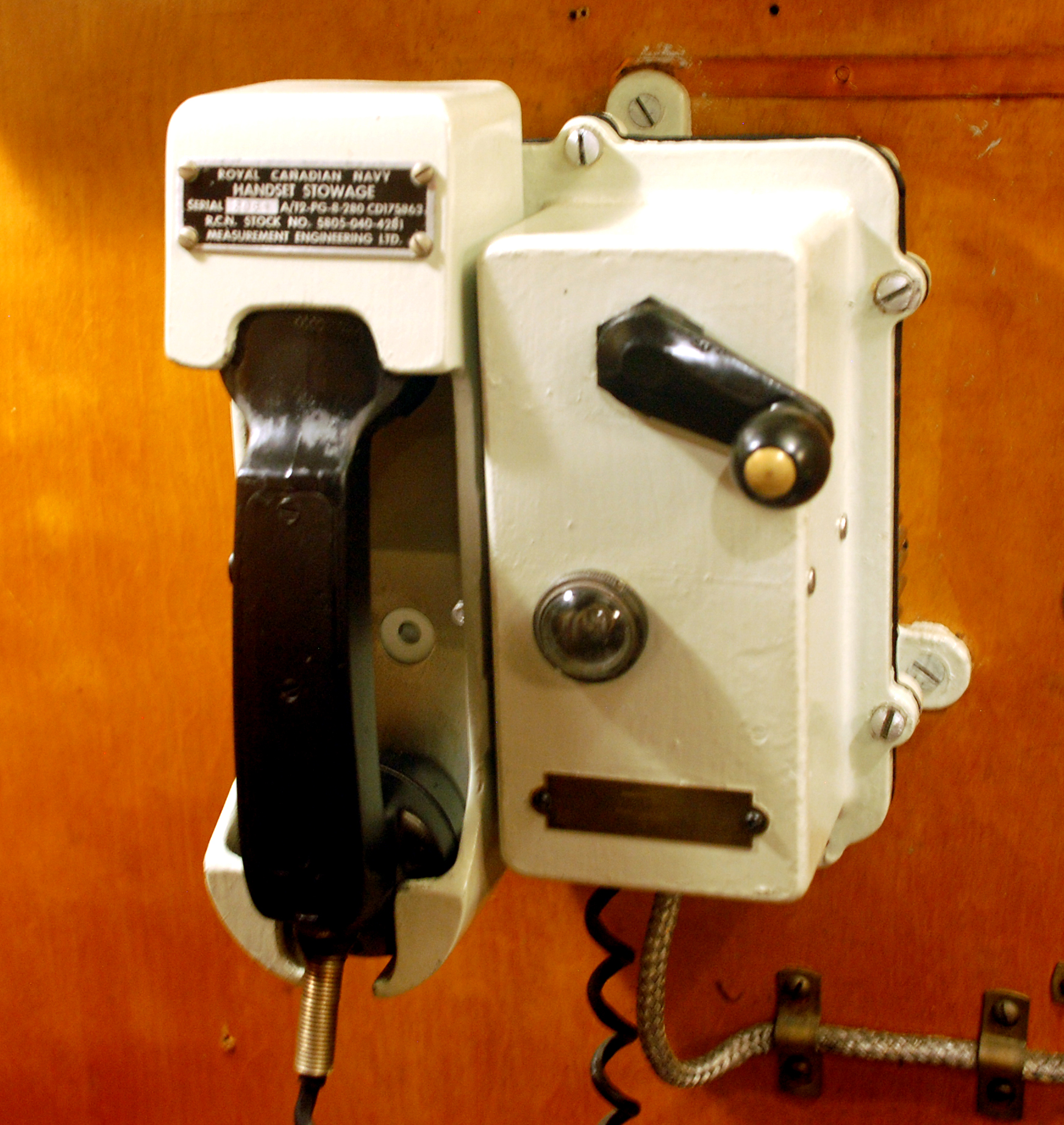
At some later date , the navy modernized
the telephones by the addition of a handset stowage assembly It was made
my Measurement Engineering part number 5905-040-4281. Not all of
the telphones were modernized as shown above.. (Photo by Jerry
Proc) |
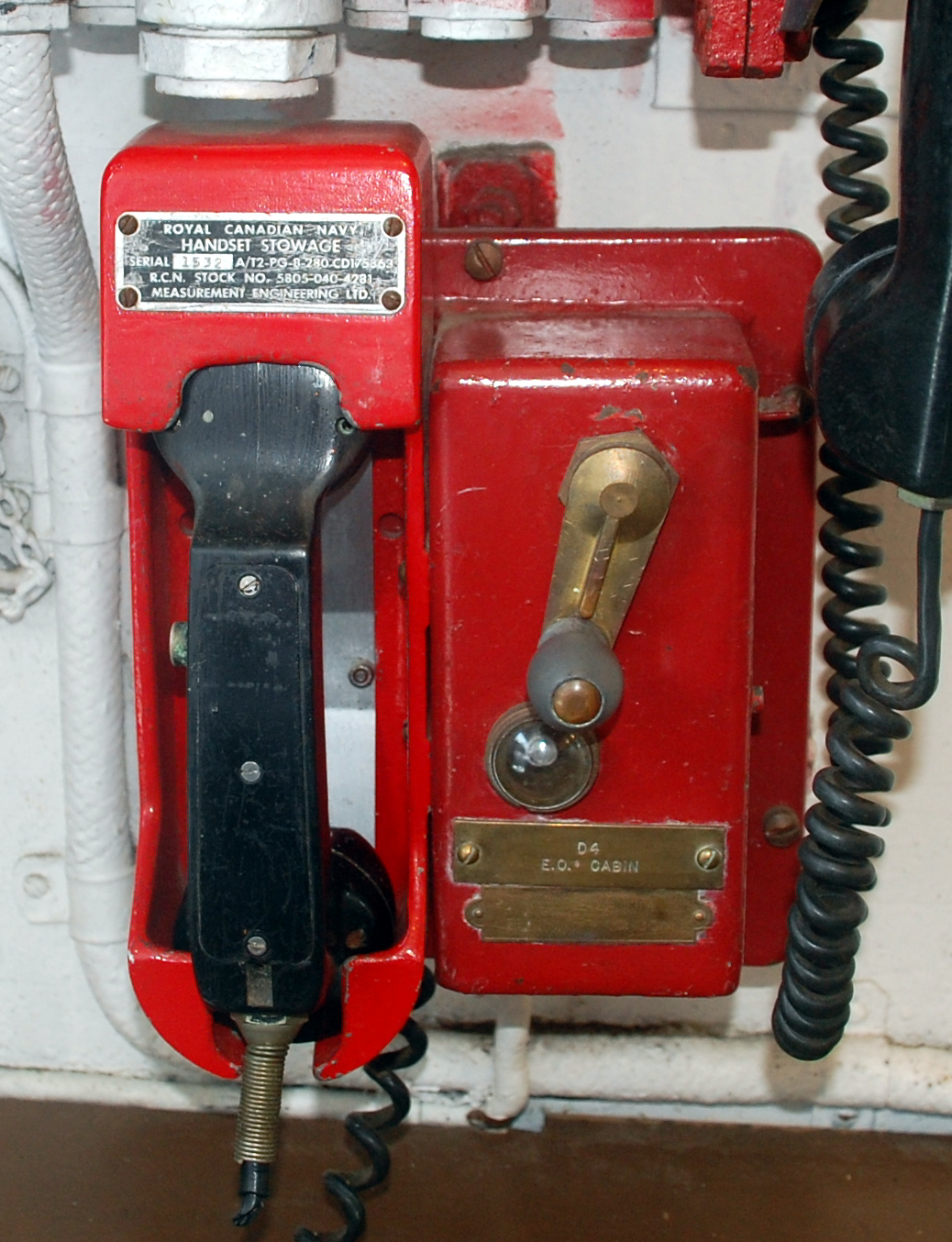 |
| All damage contols phones in HAIDA
were painted red. All of them would terminate on a panel in the Damage
Contol Office, (Photo by Jerry Proc) |
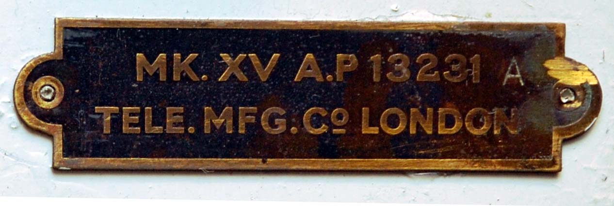 |
This is the nameplate for The Telephone Manufacturing
Company of London Eng;amd. |
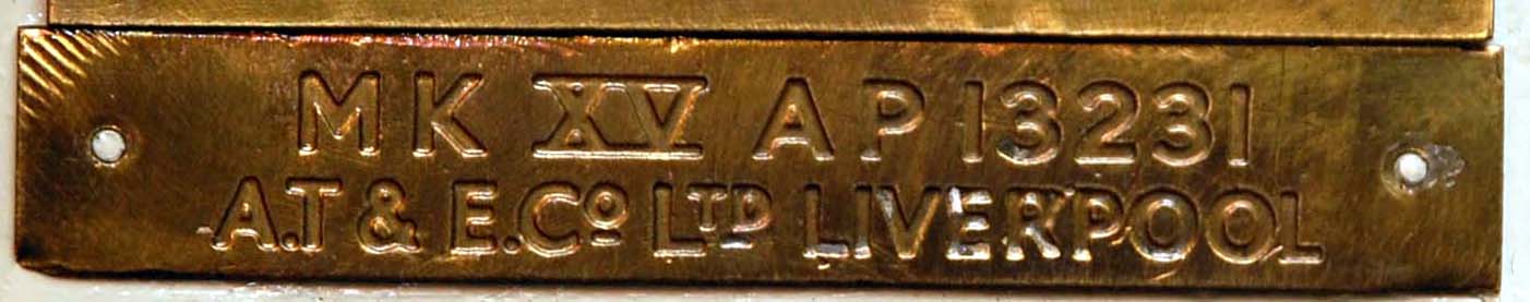 |
This is the nameplate for the AT&E company
in Liverpool. |
Sound powered telephone schematic
(Mk 15)
Voice Pipe
Besides being used for the transmission of voice traffic, the voice
pipe in Radio 1 was also used to move paper messages between the bridge
and radio room. Messages were placed in a small canister known as the 'bucket'.
This was raised and lowered from the bridge using a string known as Coston
Gunline. When there was a message destined for the bridge, the Radioman
signalled the bridge by pressing a switch next to the voice pipe. The party
on the bridge would then haul up the message. On occasion, the string would
break and the bucket became a 'bullet' which would then provide the 'receiver'
with a great surprise. Very strange items were known to travel through
those voice pipes.
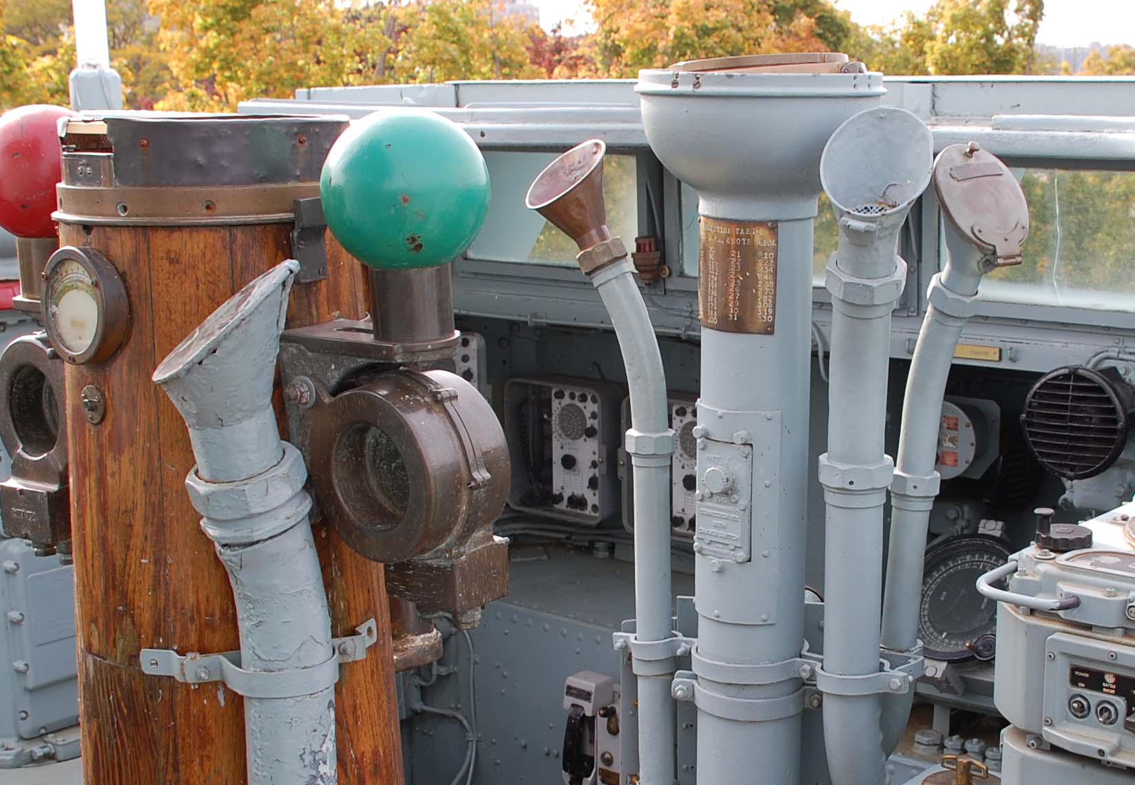 |
| Voice pipe examples on HAIDA's bridge. The
voice pipe over the desk in Radio 1 is missing the flared section. (Photo
by Jerry Proc) |
A log of restoration activities
for HAIDA's Radio 1 can be found here. .
Credits:
1) Morse Express http://www.morsex.com/ccorner
2) Spud Roscoe <spudroscoe(at)eastlink.ca>
3) Dave Blais <brodger0131(at)rogers.com>
4) Colin Blackburn <acblack(at)shaw.ca>
5) David J.J. Ring, Jr. N1EA. Former radio officer
<n1ea@arrl.net>]
6) Wayne Blenkhorn VE1BAB <wayne(a)blenkhorn.ca
7) D.J.J. Ring, Jr. n1ea@arrl.net
Back to Table of Contents
Jan 16/25


