 |
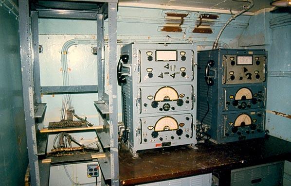
| Radio 2 - Top View |
2.0 LOCATION : On the lower deck, below the main mast on the port side.
YEAR OF INSTALLATION : 1943. Reconfiogured at least three times during HAIDA's service life. The restoration of this compartment was completed on August 27, 1994.CREW COMPLEMENT : 2
PURPOSE OF THIS ROOM : Main transmitting room for high frequency radio teletype and CW transmissions. This was also a backup to Radio 1 if it was put out if action. Radio 2 also provided additional radio circuits if Radio 1 was overloaded. When HAIDA was first commissioned, this was the HF/DF office.
For RATT transmissions, messages originating on Baudot paper tape were read on a Model 14 Transmitter-Distributor (reader) in the Message Centre. This keyed a Channel Amplifier unit in Radio 2 which then applied the keyed signal to the input of a frequency shift keyer. That, in turn , produced the 850 Hz FSK signal needed for the PV500 transmitter.
TELEPHONE CONNECTIONS: Connects with Message Centre and Radio 3.
HISTORICAL COMMENT: A radio tech who served in HAIDA in 1954/55 said the PV-500 was still in Radio 1 at the time His work shop was Radio 2 and his bench was positioned where the PV-500 is situated today. The two CM-11's were there and so was the equipment rack.
|
| Radio 2 - Top View |
 |
|
|
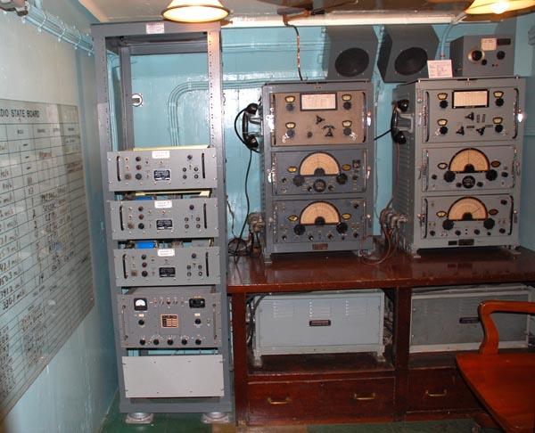 |
| Radio 2 after restoration. (Photo by Jerry Proc) |
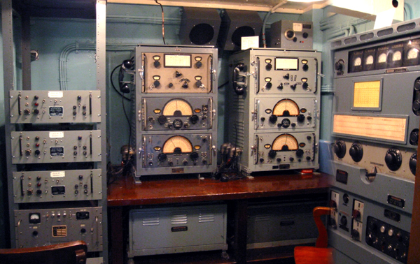 |
| Wide angle photo of Radio 2. (Photo by John Paszkat) |
DESCRIPTION OF EQUIPMENT
2.1 - Channel Amplifier UnitsSee description in Radio 1 Section.
2.2 - CM11 Transmitter/Receiver
There were two units installed in this room. Neither unit was fitted with a CW key since they were remotely controlled from Radio 1. An operator was still required to switch crystals and tune up the equipment. One CM11 #3 was connected to the 35 foot whip antenna on the port side while the other connected to a flattop antenna.
The CM11 on the right is #2 unit and the one on the left is the #3 unit. Al Goodwin HAIDA's POTEL in 1962 indicates that CM11#2 was tuned up for the 500 KHz distress frequency.The following standard RCN crystal frequencies were available for the CM11 transmitter.
The following standard RCN crystal frequencies were available for the CSR5 receiver..2.3 - PV500 Transmitter and Variants
PV500-HM2. Click on thumbnail o enlarge. (Photo by Jerry Proc) The Canadian Marconi PV500 HM was first built in 1943 and it was a high powered, CW/ICW only transmitter, capable of operating in the range between 3 to 19 Mc. Power input was 500 watts over this frequency range. Break-in keying could also be used. The HM2 variant of the PV500 operated up to 28 Mc, however, power input was reduced to 300 watts above 19 Mc. There were four, switch selectable, master oscillators that could be preset to the most often used frequencies. Alternately, four crystal controlled frequencies were also available. In addition, Interrupted CW (ICW) could be sent and tones of 400, 700 and 1000 cycles per second could be selected from the front panel. In talking with former telegraphists, there is no evidence to support the use of ICW.
Physical Dimensions: 63" H x 37" W x 25.25" D
Weight: 620 to 695 pounds depending on variant.
An additional 285 pounds if used with a rotary converter.
Power requirements : 120 VAC, 60 Hz, 1800 watts or rotary converter.
Antenna Impedance : 5 to 200 ohms resistive.The PV500 was used as both a CW and RATT transmitter for naval traffic. In the 1962 time frame, it was used on the amateur bands as station VE0NV when there was no naval traffic. The following standard RCN crystal frequencies were available for the PV500 series transmitters. .
When used in RATT service, the PV500 was keyed by a frequency shift keyer which was connected to the teletype distribution panel in the Message Centre. Normally, the T-D was the input device, however, the Teletype could have been used for that same purpose, but with less efficiency. As with the majority of the equipment, the PV500 was attached to the remote control system, but someone still had to manually change frequencies and tune it up.
Keith Kennedy, of Surrey B.C., states that "PV500's were notorious for ground loop problems and one made sure that you kept one hand in your pocket while tuning them. Placing your hand on the cabinet to brace yourself against the ships roll could result in a really fine 'attention grabber' in the form of an AC buzz. Many Radiomen tuned the PV500 HM2's by watching the power amplifier through the front panel window. When the plate was cherry red but not white, the final stage was considered to be tuned. As an additional tuning aid, a small fluorescent bulb was taped to the antenna feed line and the final would be tuned for maximum brightness. On some PV500's, the front bottom left power supply cover panel can be found somewhat dented. This was normal and was caused by having to kick it there in order to ensure that the power supply interlock engaged.
Since there was no drive level control on the PV500 HM2, there was excessive drive at lower frequencies and insufficient drive at high frequencies. Multiplier stages had to be detuned to obtain the desired drive levels. To reduce chirp on CW, the multiplier stages were keyed while the oscillator was held on for the duration of a 'word'. This reduced chirp to the first letter of each word sent and permitted the use of break-in operation. In the PV500 HM3, there were design changes to overcome deficiencies of the previous models. A driver stage and drive level control were added. Frequency shift keying capability was added. In the previous models, there was a large power loss in the trunking to the antenna, so the antenna tuner was removed from the transmitter and was re-designed for remote operation".
The PV500 HM currently on display was acquired from HMCS Griffon Naval Reserve Division in Thunder Bay Ontario, but HAIDA was fitted with the PV500 HM2 when she was paid off. To see the internal construction of the PV500, select this link. (Photo by Jerry Proc)
2.4 - Transmission Line Tuner - E886
This unit was fitted to CM11 #3 on Oct 29/62. Internally, it contained several fixed and one variable inductor which could be switched in or out. Also installed, was transformer-rectifier assembly whose purpose is not known. At this time, it is not known how the E886 operated in conjunction with the CM11. The unit which is on display is a mockup and was carefully crafted by Jerry Proc .The original unit was built by the Canadian Navy Electrical Laboratories (CNEL) (Photo by Jerry Proc) E886 document is here.
2.5 - XFK107 Frequency Shift Keyer
The Frequency Shift Keyer converted the 60 milliampere current loop from Radio 1 into control signals which would then frequency shift key the PV500 transmitter. With frequency shift keying, mark and space signals, in essence, cause the transmitter to be FM modulated with a fixed frequency deviations.
A frequency shift keyer was used in lieu of the oscillator stage in the PV500 transmitter. The keyer produced an RF carrier of constant amplitude and frequency which would be shifted 850 Hz depending upon whether a mark or space condition was being sent. For low frequency operation, the frequency shift was 200 Hz. Keyers used by the navy produced a carrier signal in the range of 2 to 5.5 Mc with selectable shifts of up to 1000 Hz. In later variations, keyers could operate in the 1 to 6.7 Mc range. (
The following standard RCN crystal frequencies were available for the XFK107 keyer when paired with the PV500 series transmitter: (Photo by John Paszkat)
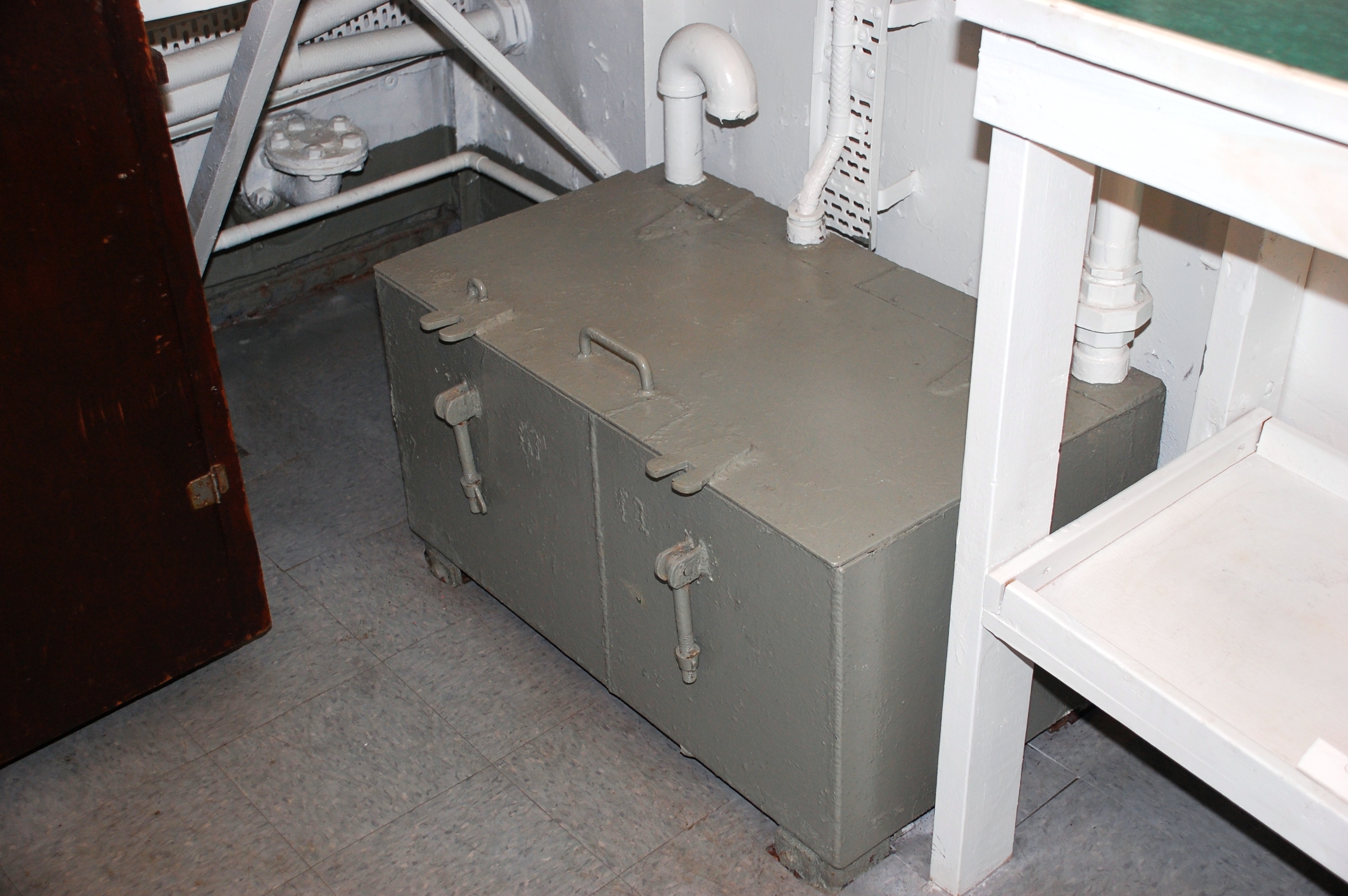
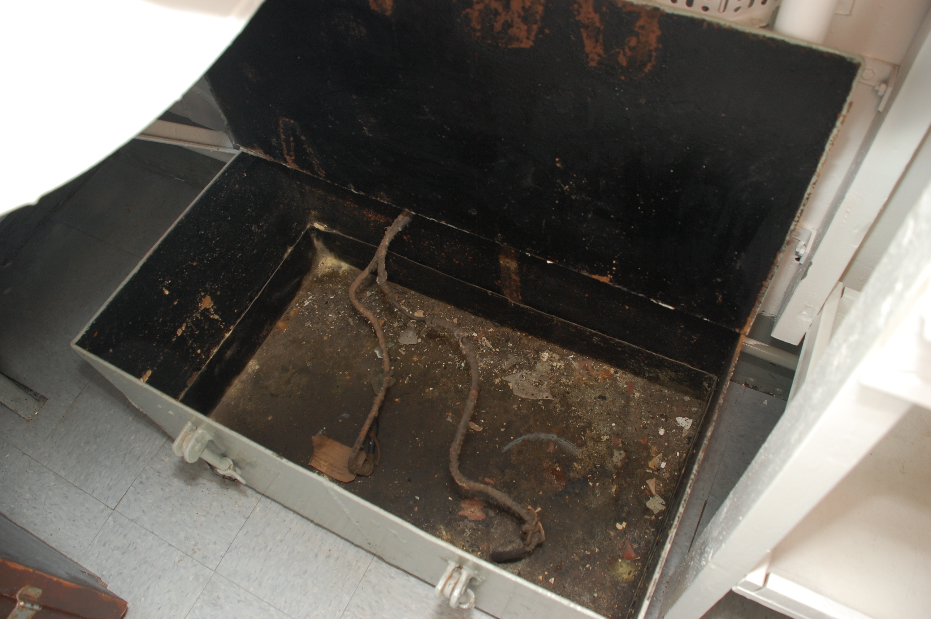
This is the motor alternator for one of the CM11's in Radio 2. It converts 24 VDC to 115 V 60 Hz. Behind it is the starter unit. The knife switch to the left is the battery charging panel . In one position the battery is connected to the charger. In the other position, the battery is connected to the motor-alternator input. Click on image to enlarge. . (Photo by Jerry Proc) This is the battery enclosure for one of the CM11 transmitters in Radio 2. The box is about 2 feet high by 18 inches deep and 1 foot high. Emergency power from the batteries fed a motor-alternator set just outside of Radio 2. ( Photo by Jerry Proc) Due to the amount of debris at the bottom of the battery enclosure, it was not possible to see any battery "footprints". (Photo by Jerry Proc) 2.6 - Other Information
Just like Radio 1, this room is lined in sheet copper to reduce radio frequency interference both inbound and outbound. In order to realize the full benefits of shielding, the door to Radio 2 would have to remain closed when operating. It was not a place for a Sparker who was susceptible to claustrophobia.
In 1984, a Korean war vet had indicated that there was a false compartment on the port side of Radio 2 where spare tubes and parts had been stored. Perhaps they were still there. Unable to contain his curiosity, HAIDA's Electrical Officer, Lt. Frank Moore disassembled the panelling and did indeed find the hidden niche. Unfortunately, there were no treasures to be discovered.
CM11 #3 was fitted with a hybrid transmission line. From this CM11, a bare, 5/16 diameter copper tube was suspended on standoff insulators. A feed through insulator passed the RF signal from the ceiling of Radio 2 to the exterior of the lower deck. Attached there was a length of RG 18/U coax, stripped, so only the dielectric jacket remained. Finally, this co-ax connected to the port aft whip antenna. (RG 18/U coax is one inch in diameter using a #6 solid copper wire centre conductor).
Prior to Radio 2 being repainted in 1994, there was evidence of a shelving unit which was affixed to the aft bulkhead of Radio 2. Care was taken to record the "fingerprint" of the unpainted area. prior to it being covered with a fresh coat of sky blue paint, If anyone is inclined to build a replacement shelving unit, please contact Jerry.Proc@sympatico.ca. A plan, showing the dimensions, can be found here.
Whip Antennas
Canadian Forces Fleet Technical Bulletin # O 03/1 (ORD) dated 30 June 1970, details the part numbers of 35 foot whip antennas. This bulletin supersedes FTB O 03/1 dated 5 February, 1969.
1 The new Canadian-made fibreglass antenna replaces the 35-foot sectional aluminum whip antenna.
2 AS-5061/SRT fibreglass whip antenna, NSN 5985-21-856-0312 is being brought into service to replace the sectional aluminum whip antenna NSN 5985-21-401-2016, and its base insulator, NSN 5970-21-324-1980.
3 Replacement is to be made as an existing whip antenna or insulator, of a particular installation, becomes defective. This is not an 'across-the-board' replacement.
4 There will be no further procurement of components or spares for the sectional antenna.
Sometime around the mid 1990,s HAIDA's four whip antennas were refurbished. This entailed the removal of the copper bonding straps between antenna sections, a thorough cleaning of the connection area for the new copper straps, the stripping of the old paint, an application of zinc chromate primer and finally a black and while enamel finish.
The reason for this black/white paint scheme is simple. The bottom third of each whip antenna is painted black so that any soot emissions will land near the bottom portion of the whip and not be seen. The white portion is just to make it look spiffy. On a cloudy day, the white portion of the whips disappear when viewed against clouds. This creates the illusion that the black portion of the whips are suspended mid-air.
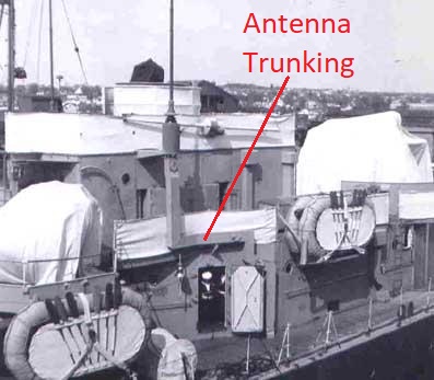
Taken in May 1957, this aft, port side view of HMCS Iroquois illustrates the trunking from Radio 2 to the aft. port whip antenna. Originating at deck level to the right of the door, it traversed the exterior bulkhead and mated with the bottom portion of the antenna sponson. HAIDA's trunking was identical in appearance. An enclosure of 9 inches by 11 inches would produce a characteristic impedance of 180 ohms. (Photo courtesy of Lawrence Redman)
 |
| Closeup view of the aft sponson . One whip was for the PV500 transmitter while the other was for one of the CM11s. (Photo by Jerry Proc) |
On many older ships, open wire transmission line was commonly used because coaxial cable was rather new and had not been produced in a type that would handle the required power levels. Open wire line had its advantages in that the radio operator could tune the transmitter over a wide frequency range. Among the disadvantages, were safety and the difficulty of preserving watertight integrity. In many instances, it was within handy reach of the unsuspecting seamen even though there were 'Danger - WT Transmitting Antenna' signs posted in the appropriate spots. This hardly constituted sailor-proofing. In other circumstances, the open line was fitted with a metal enclosure (trunking) or a wire mesh screen which took up space, a resource which was always in short supply on a ship. Open line also had the potential to cause mutual interference to other wiring within the ship.
 |
This schematic shows how CM11 #3 in Radio 2 connects to the port aft whip antenna using bare copper transmission line called trunking. . Unfortunately, the trunking was razed decades ago to prevent water seepage. Click on image to enlarge. |
Once suitable coaxial cable was developed, most of the open wire transmission line was removed. The ease of installation, the saving of space, maintenance, and improved watertight integrity were advantages which could not be dismissed. Co-ax cables were also manufactured with armour which among other advantages, prevented or severely retarded the spread of fire.Stew Patterson of Dawson Creek, B.C. relates a humorous anecdote while he served aboard HAIDA. "I remember Radio 2 very well as it was my cleaning station and I spent many hours polishing brass in there. The PV500 was a very fickle piece of equipment and at times you would get zapped while trying to tune it. Peter Foote (alias - Panic Pete Feet) was the P2 at that time and was very nervous around that beast.
John Ovens and myself were sent down to clean up Radio 2. While we were down there, the P2 came down to tune up the PV500. Meanwhile, John started to mischievously glance at the tool box in which he stored his diving weights. John then glanced at me, then back to the tool box. Without a word, he picked up the toolbox and dropped it behind the P2. Peter almost went through the deckhead but we made a quick exit through the door and up the ladder. Thank goodness he stayed airborne long enough for us to get a head start or we would have been tuned up much better than the PV500".
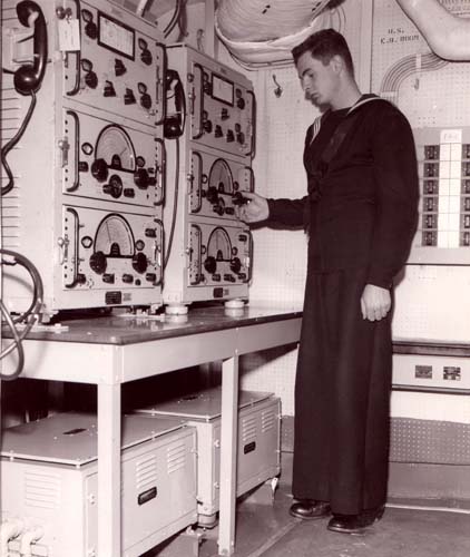
Dave Blais, RCN radioman at the time, adjusts one of the two CM-11 transmitters in this dual CM-11 installation aboard HMCS Restigouche in 1959. (RCN photo from the collection of Dave Blais) TRANSMITTER to ANTENNA CONNECTIONS
CM11 #2 connects the port after flattop.
CM11 #3 connects to the port after whip.
PV500 connects with the starboard aft whip.CM11 #3 used to be connected to its whip antenna via bare copper tubing (aka antenna trunking) but that was stripped out decades ago.
It should be noted that the aft whip antennas aboard HAIDA are 28 feet in length rather than the old standard length of 35 feet. The 28 foot antennas were donated from HMCS Mackenzie to substitute for the original ones. The forward 35 foot whip antennas are the original ones.Here are the dimensions f or the five section, 35 foot whip. Each section is 83 inches.
The base section is 3 inches in diameter.
Next up, that section is 2.75 inches in diameter.
Next up, that section is 2.0 inches in diameter.
Next up, that section is 1.75 inches in diameter.
The topmost portion is 1 inch inch in diameter.At each joint, there is a copper braid bonding strap which ensures connectivity to all sections of the whip antenna.
A log of restoration activities for Radio 2 can be found here.AMATEUR RADIO
After a very long absence, a permanent amateur radio station has been established aboard HMCS HAIDA using call sign VE0NV. This is the same amateur radio call sign that was used when HAIDA was in service.
Now housed in Radio 2, is an ICOM 7300 transceiver running 100 watts into a LDG Electronics remote antenna tuner and connected to the 28 foot aft port whip antenna. Preliminary testing had indicated favorable operation on the traditional and WARC bands allocated to the amateur radio service. It even works on 6 meters with a very low SWR.
The station was officially launched during the "Museum Ships On The Air" event held on the weekend of June 6 and 7, 2026. Rick Bialachowski made the first contact at 10 :00 on Saturday, June 6 with a contact in Wisconsin.
On day one of the event, the sun emitted a Coronal Mass Ejection which completely shut down high frequency communications. Conditions recovered and by Sunday June 7, a total of 54 contacts were made. Currently, the plan is to operate the station whenever the ship is open, provided that volunteers are available.
By establishing VE0NV in Radio 2 , it gives radio volunteers the opportunity to contrast old and new radio technology to the ship's visitors.
Many thanks go out to Rick Bialachowski who was instrumental in repatriating call sign VE0NV for HAIDA , to Friends of HAIDA who provided the funding to buy the amateur radio hardware, to Chris Cuthbert who installed the station and to Jerry Proc who provided counsel.
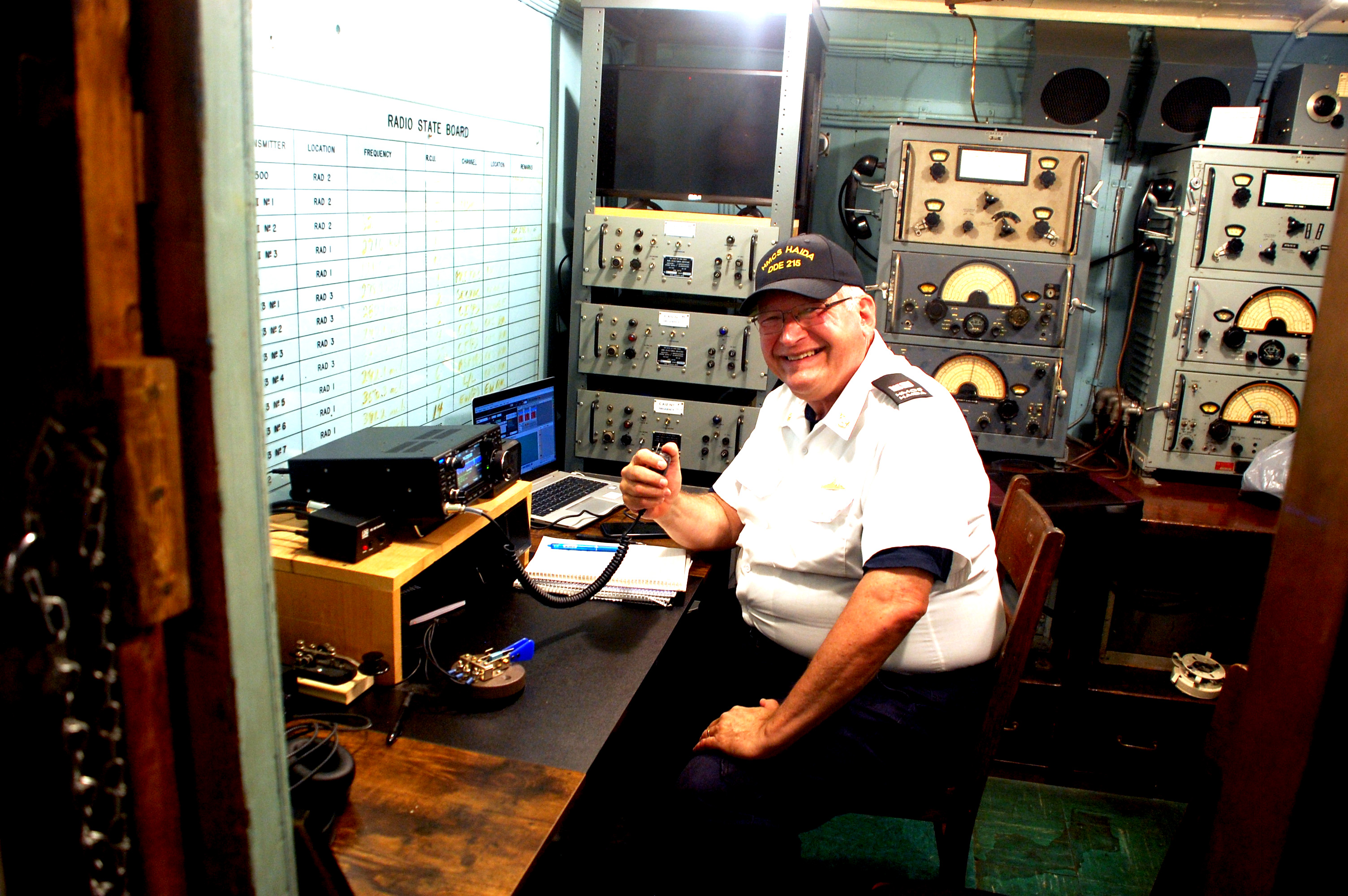 |
| Chris Cuthbert, VE3PKY at the controls of VE0NV. In the background is equipment native to HAIDA when she paid off in 1963 |
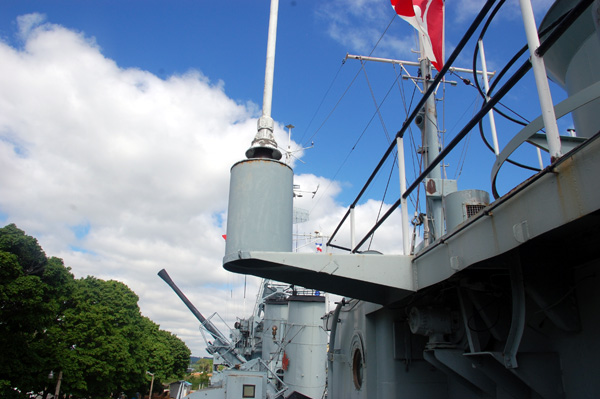 |
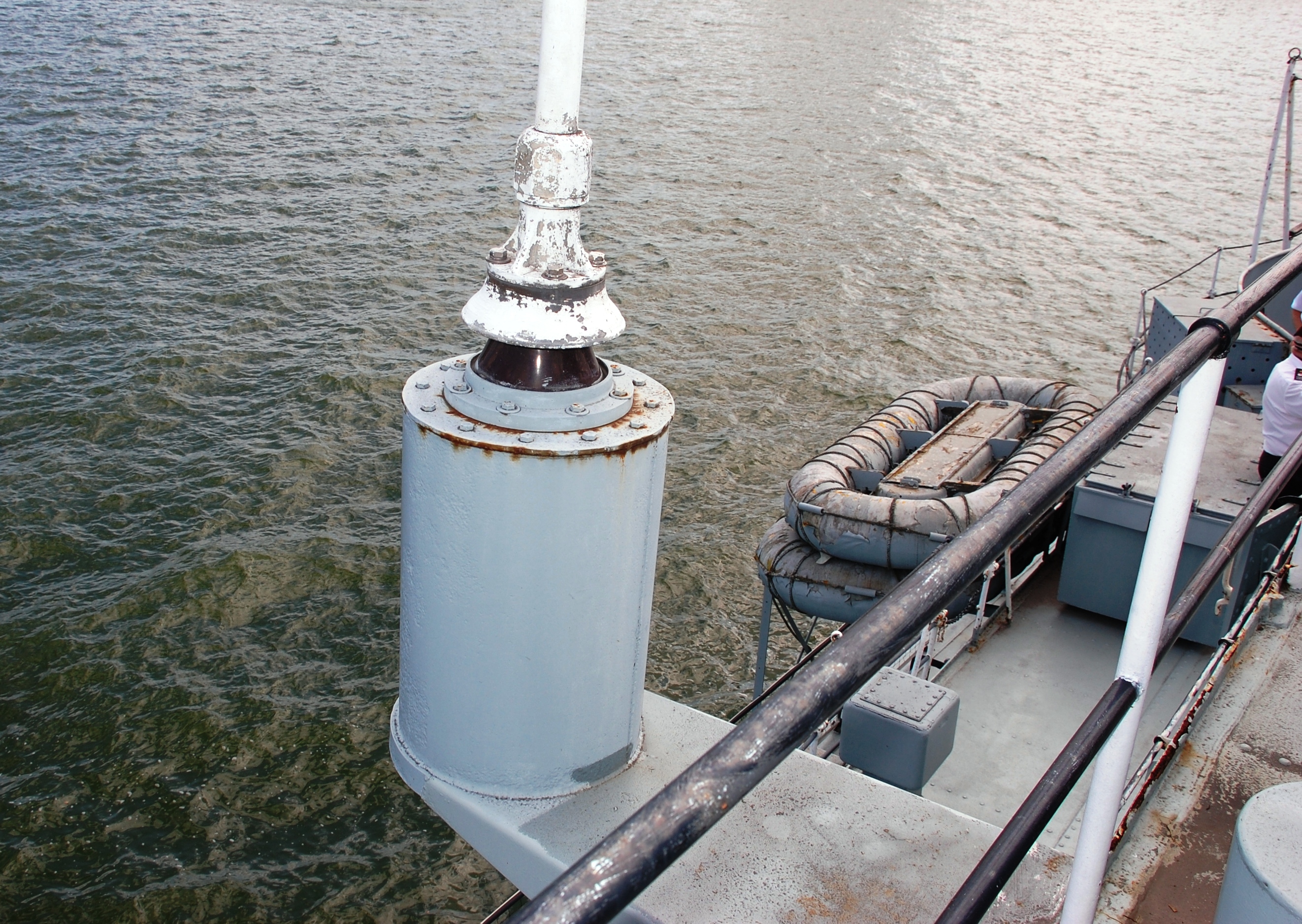
| The cylinder of metal which holds up the 28 foot whip antenna is called a sponson. |
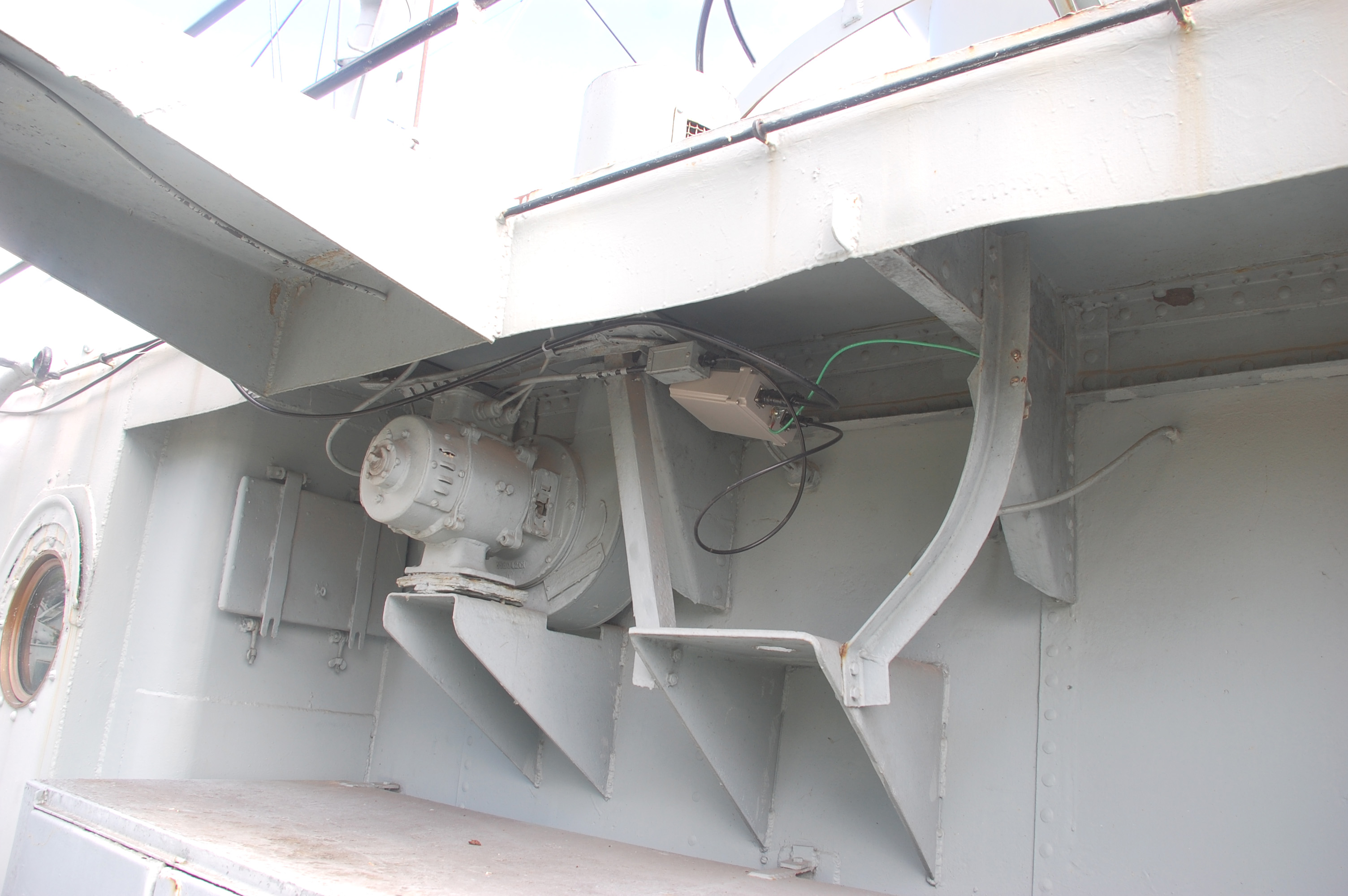 |
| Tucked neatly away, under the steel of the aft superstructure, is the LDG Electronics Model RT-RC100 remote controlled an antenna tuner, In HAIDs case, it yields SWR readings approaching 1:1. |
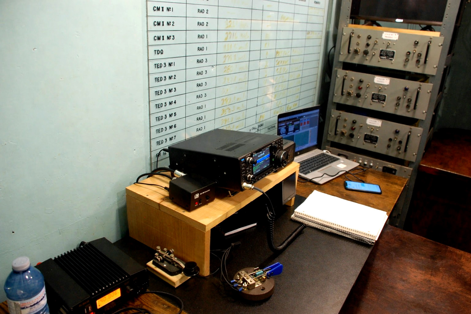 |
| VE0NV station equipment. The three gray rack panels are Channel Amplifiers, equipment which was native tio HAIDA in 1963. |
| All photos in this table by Jerry Proc |
The Hamilton Spectator published a story about VE0NV. Page 1 Page 2 .
Contributors and Credits:1) Dave Blais <brodger0131(at)rogers.com>
July 9/26


