RADIO ROOM 4 DESCRIPTION - 1962 FITTING
LOCATION : Located on starboard side below the lattice mast.
YEAR OF INSTALLATION : Before 1956. Restored to 1962
configuration on Aug 1, 1993.
CREW COMPLEMENT : 2 but not at the same time. Any crew
working in this room would require a top secret security clearance. The
Captain also had access to Radio 4 provided he took a security briefing
course beforehand.
PURPOSE OF THIS ROOM:
* This was the electronic warfare room but mostly referred to as simply
"Radio 4". It was capable of providing direction finding services in the
MF radio bands plus the interception of radar transmissions in the super
high frequency (SHF) bands.
* For monitoring and recording of tactical radio traffic using a Hammarlund
general coverage receiver and tape recorder.
* Provided two-way high frequency communications between electronic
warfare rooms of HMC ships.
TELEPHONE CONNECTIONS: Connects to Radio 1, the OPS room and
the bridge.
 |
|
Deck plan for Radio 4.
|
 |
| Radio 4 as found. The layer of dust is residue from the sandblasting
of 1982. (Photo by Jerry Proc) |
 |
| Radio 4 after restoration in August 1993. (Photo by Jerry Proc) |
 |
| Radio 4 in April 2004, after the addition of the AN/SRC-501 mockup
to the shelf, top middle . Bottom row (L-R) Webcor reel-to-reel recorder,
SP600 general purpose receiver and the Marconi FM12 D/F set. (Photo
by Jerry Proc) |
GENERAL INFORMATION
According to Cdr. R.A. Willson of Toronto (Ret'd), Radio 4
or its equivalent, depending on the type of ship, was also known as the
Electronic Warfare room (EW), Electronic Warfare Control Room (EWCR), EW
Shack, or EW Hut depending on the era. In the Fleet or Task Group
Communications Plan there would have been an EW Primary communications
circuit, EW(P) in the UHF Range and an EW Secondary circuit, EW(SEC), in
the MF/HF Range. EW(P) would be used as the control circuit for tactical
EW and EW(SEC) used when units were outside UHF range. In Radio 4, the
EW(P) circuit was provided via the RCU mounted on the forward bulkhead.
EW(SEC) may also have been used as a "yak" circuit if the Radio Silence
Policy permitted, since it was not normally monitored in the Ops Room or
on the Bridge like the EW(P) circuit.
DESCRIPTION OF EQUIPMENT
| 4.1 - AN/SRC 501 Transceiver
 The AN/SRC-501 was designed primarily for marine installations, and intended
for ship-to-ship or ship-to-shore communications over short distances.
In the RCN, it was used to provide a secondary communications circuit EW(SEC)
between electronic warfare rooms using the high frequency radio band. It
was generally used when ships were beyond UHF line of sight range. Radiotelephone
transmission and reception used any one of four, crystal controlled frequencies
in the 2 to 4 MHz band. Optionally, the receiver section could be continuously
tuned for reception in the 0.5 to 1.5 and 1.5 to 4 MHz bands. Twelve watts
of power was delivered to an antenna tuning unit in the base of a 19 foot
whip mounted on the starboard side of the bridge. The most common fault
with the system was moisture leakage into the antenna base due to being
exposed to the elements. One former CS rating offered his personal comment
about the operation of the AN/SRC 501. "Its main use was an intercom between
Radio 4's. A good megaphone was just as good, if not better". (Photo
courtesy RCN)
The AN/SRC-501 was designed primarily for marine installations, and intended
for ship-to-ship or ship-to-shore communications over short distances.
In the RCN, it was used to provide a secondary communications circuit EW(SEC)
between electronic warfare rooms using the high frequency radio band. It
was generally used when ships were beyond UHF line of sight range. Radiotelephone
transmission and reception used any one of four, crystal controlled frequencies
in the 2 to 4 MHz band. Optionally, the receiver section could be continuously
tuned for reception in the 0.5 to 1.5 and 1.5 to 4 MHz bands. Twelve watts
of power was delivered to an antenna tuning unit in the base of a 19 foot
whip mounted on the starboard side of the bridge. The most common fault
with the system was moisture leakage into the antenna base due to being
exposed to the elements. One former CS rating offered his personal comment
about the operation of the AN/SRC 501. "Its main use was an intercom between
Radio 4's. A good megaphone was just as good, if not better". (Photo
courtesy RCN)
|
The following standard RCN crystal
frequencies were available for the transmitter portion of the
SRC-501.
The following standard RCN crystal
frequencies were available for the receiver portion of the SRC-501.
 |
| Hi-res photo of the AN/SRC-501. (Photo # O-15197 courtesy DND, Canadian
Forces Joint Imagery Centre provided via by Robert Langille) |
|
 |
| A mockup of the AN/SRC-501 built by Jerry Proc VE3FAB. No real example
of this set has ever been found. (Photo by Jerry Proc) |
| 4.2 - AN/UPD-501 Radar Band D/F Receiver
HISTORY
Robert Langille provides some background material. "The UPD-501 was
registered as a JETDS device from 1952 to 1995. During its service life,
there were three variants:
* Variant 1 was fitted to the Tribal and Prestonian Class ships. - There
were only X band horns fitted to a plate which sat atop the foremast.
* Variant 2 saw service on the RCAF's Avenger AS3M, Lancaster MK X,
P2V7, Neptune (Temp), CS2F Tracker and also aboard HMCS Bonaventure.
* Variant 3 was applicable to the St Laurent, Annapolis, 280,
and IRE class of ships. It was also found on Mackenzie
and Saskatchewan. Early fits in late 1950's may have been as Variant 2
but later evolved
to include J Band.
EMI Cossor produced the units for the initial procurement. During the
1960's EMI was acquired by Raytheon UK".
DESCRIPTION
A UPD-501 was a High Probability Radar Early Warning directional finding
receiver which was used to detect radar emissions on the SHF radar bands
and gave some indication of the wavelength in use, bearing, and the antenna
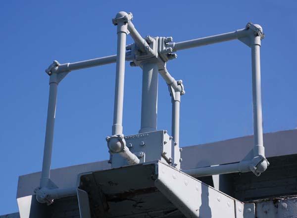
rotation period. The receiver was connected to a horn antenna assembly
which was mounted on the foremast top and connected to the receiver by
RG55/U coax. Initially, the UPD 501 horn antenna (circa 1953) was designed
to monitor X band radar only. This was the version fitted on HMCS HAIDA
and depicted below.

In the above diagram, 1N23WE diodes located in the antenna housing acted
as signal detectors. Changing these diodes could be a very interesting
experience in harbour, let alone at sea. In the 1970's, a two band version
(X and L) was introduced. Later, the antenna was redesigned for coverage
in three radar bands. The multiband version was a two piece, symmetrical
unit. Each vertical section was 34 inches long and consisted of four cylindrical
antenna modules that were bolted together. The original concept of the
"can" enclosure was devised by a RCAF engineer at Shearwater , Nova Scotia
while trying to fit the UPD to an Avenger aircraft in 1955.
Click om image to enlarge.
The three band UPD antenna had the following coverage:
| ANTENNA ASSEMBLY # |
BAND
|
FREQ. COVERAGE |
|
|
|
| AT-5006 |
S
|
2.3 to 5.5 GHz |
| AT-5007 |
X
|
5.5 to 10.8 GHz |
| AT-5027 |
K
|
10.5 to 20 GHz |

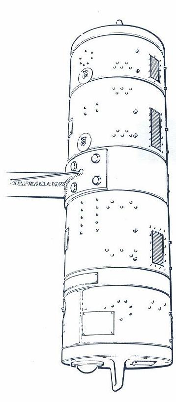
This is a detailed sketch showing one side of the UPD-501 multiband
antenna.
(Drawing courtesy RCN)
The design of the UPD501 was simple. In the set itself, there were four,
wide-band radio frequency amplifiers, one for each 90 degress of the compass
rose. The outputs of the amplifiers would be applied to the four plates
of a cathode ray tube and the relative signal strength caused a blip to
appear on a CRT. This blip was appropriately deflected to visually indicate
the relative bearing of the incoming signal. In the absence of any signal,
a spot of light would simply appear in the centre of the CRT. Upon receipt
of a radar emission, an audible alarm was also triggered. This alarm could
be monitored by a loudspeaker or headphones.
Pat Barnhouse, a former Electrical Officer and Radioman Special aboard
HMCS HAIDA outlines a serious problem with the original UPD 501 antenna
design and how it was rectified. "Our ship an inoperative UPD 501 set.
It turned out that the crystal detectors in the horns had been burned out
as a result of receiving an overload of RF from a nearby high powered radar,
probably an SPS 10 or 12 sitting close to us in Halifax harbour.
The problem was that there were no shutters on the original UPD 501 horns
to protect the sensitive 1N23 mixer diodes and this burnout problem became
endemic. Replacement was compounded by the horn placement on the bottom
of that flat plate at the top of the mast extension, requiring a dockyard
crane to effect replacement. The later multiband versions of the
501 came with the antennas mounted in "cans" that had shutters over the
horn mouths. There was only one drawback to the UPD501 - it could not be
used if the ship's own radar was operating. During the 1970s, the 280
Class ships were introduced with EWIS Equipment and the DPTSA. Both of
these units used the UPD 501 as an input sensor until replaced by CANEWS.
The UPD501 system was replaced in most HMCS ships when they were retrofitted
with CANEWS ( ie AN/SLQ-501) during the 1980s. Most schedule retrofits
were completed by 1989/1990. CPF and new city class FFH ships were never
fitted with the UPD system they were scheduled to be fitted with CANEWS.
(Image
courtesy RCN) |
| |
|
Notes on the UPD-501 by Ken Macdonald.
|
 |
| This X-band horn has been extracted from the AT-5007 "slice" of the
UPD-501 multi-band antenna. The portion in the center and left is
a motor-operated shutter which when closed, would protect the signal
diode against unwanted RF energy. (Photo by Jerry Proc). |
 |
|
UPD-501 receiver aboard HMCS HAIDA. (Photo by Jerry Proc)
|
 |
|
UPD-501 Power Supply (Photo by Jerry Proc)
|
Curt Bowles, VE3ZN, relates one experience that he had with the UPD-501.
" I commissioned HMCS Athabaskan 282 . In those days I had moved from Comms
to Electronic Warfare (EW) as it became an official trade and formally
manned by CS rates. In those days were still operator-maintainers.
The EWCR (Electronic Equipment Control Room) didn't have all the equipment
up and running when the ship was commissioned. So as techs, we were
involved in setting up the EW Equipment. We had a pair of UPD-501s
plus their antennas that were very sick and parts were hard to come by.
I was a licensed ham as well (VE1AYE) and often we would go down to
Junky-Jims (a scrapyard just outside of Halifax) in search of
electronic equipment including the Navys or bits and pieces that could
be used for Ham Radio. On one of my trips I found four scrapped UPD-501s
and their antennas. Needless to say I picked them up for a few bucks
and brought them back to the ship and was able to retrofit the existing
UPDs and antennas on Athabee. I managed to get them back in working order
I still laugh about that event."
The AN/UPD-501 was on the RCN's books from 1952-1995
4.3 - FM12 MF/DF Receiver
Designed by Marconi in 1942, this was a tuned radio frequency, direction
finding receiver with an frequency range of 42 to 1060 kc and required
220 VAC input power. The FM12 was considered to be a D/F 'outfit' or system
and it incorporated the Model FMB receiver. In 1943, the outfit was re-designed
for use in submarines and was known as the FM11 which incorporated the
FMA receiver. On HAIDA, input power was supplied by a 120 to 220 step up
transformer. Power consumption was 60 watts. A directional, fixed frame
antenna, was mounted over the wheelhouse and was connected to the FM12
inputs via dual connector blocks and RG57 coax. The STB INNER VERTICAL
was the 'sense' antenna for the FM12 and Marconi recommended that the aerial
be 30 to 40 feet in length. A wall mounted, gyro repeater provided reference
bearings for the operator.
The FM12 was a very good direction finding set for its day. In taking
a bearing, the use of the multi-purpose switch was very important. An operator
would first tune in the signal of the target station with the Aerial switch
in the search position. Then, with the switch in loops, a minimum strength
on the outside compass scale of the goniometer was found. Lastly, the operator
would place the Aerial switch in the sense position and would rotate the
goniometer slowly clockwise. If the signal faded away, the minimum position
was the true bearing. Had the signal risen, it indicated a reciprocal bearing
and true bearing would be found 180 degrees on the opposite side of the
scale.
This unit was originally fitted in Radio 1, however, Jack Raine of Vancouver
states that in the '43 to '44 period, the FM12 aboard HAIDA was not used
for the stated purpose of intercepting enemy radio transmissions. Instead,
it was used as a navigational check to aid in operations in the area of
Scapa Flow to Russia, Iceland and Spitsbergen. When HAIDA was transferred
to the Plymouth Command in 1944, the unit was not used to the best of his
knowledge. The FM12 was mainly used for navigational direction finding.
On occasion, it would be used to get a MF bearing on a 'target'. This could
be another naval vessel, a merchant vessel or any vessel in distress. On
Nov 20 1962, the FM12 was moved from Radio 1 to Radio 4. It must have been
quite a job as the FM 12 weighs 211 pounds.
An
FM12 manual can be found here.

|
|
The FM-12 as fitted aboard HMCS HAIDA. (Photo by Jerry Proc)
|
 |
| FM-12 loop antenna. (Photo by Jerry Proc) |
4.4 - SP600-JX Receiver
In the late 1950's, the standard EW/HF receiver both ashore and afloat
was the SP600. Many Chief Radiomen would give a fair 'price' to have one
installed in Radio 1, particularly to copy the fleet broadcast. Eventually,
the SP600 was fitted into main radio offices only because the Racal series
of receivers were being introduced into EW service and supplementary shore
stations. The SP600JX was a twenty tube general coverage receiver made
by the Hammarlund Manufacturing Company and provided coverage in the bands
of 0.5 to 54 MHz. The J in the model number indicated that MIL spec components
were used in the design and the X means that the unit was equipped with
crystal control. In Radio 4, the SP600 is connected to the STBD OUTER VERTICAL
antenna using RG22/U (95 ohm) coax. Two characteristic features of this
receiver were the gold plated tuning capacitor and frequency coverage up
to 54 MHz. Both the SP-600J and SP-600JX were used by the RCN. Although
both the Radioman BRCN 3037 (1963) and Radioman Special BRCN 3040 (1961)
manuals describe the SP-600J, the Radioman Special manual actually shows
a photo of the SP-600JX. (RCN photo)
In the late 50's, the EW/HF listening receiver, both ashore and afloat,
was the Hammerlund SP600, which was far superior to the Marconi CSR5 series.
In fact, many Chief Radiomen would give a fair "price" to rabbit an SP600
into Radio One, particularly for the fleet broadcast, because of its stability
and sensitivity. When the SP600 finally did get in to Radio One's, it was
because the Racal series were coming into use in EW and supplementary shore
radio stations. They were that much better than the Hammerlund.
 |
| SP-600 receiver. (Image courtesy Kurrarjong Radio Museum) |
4.5 - WEBCOR Tape Recorder
The Webcor recorder can be best described as a suitcase style, reel-to-reel,
portable tape recorder, made by Webcor. It was shuttled between Radio 1
and 4 which likely explains why there is no listing of this gear on the
electrical diagrams. When stationed in Radio 4, the recorder was connected
to the SP600 receiver and was used to monitor CW traffic from Russian Electronic
Intelligence Ships (ELNIT) operating on the 4 and 8 MHz bands. These were
the famous Russian "fishing trawlers". When HAIDA returned to port, the
tapes were sent to Gloucester Ontario for analysis by naval intelligence.
In other ships such as SWANSEA, the tape recorder remained fixed.
ABRS Spud Roscoe says that aboard HMCS Swansea, there was no specific
procedure to copy the Russians. Therefore, he copied all the traffic he
could using a typewriter instead of the tape recorder. He used the 2 mc/s
band because Naval Radio Station COVERDALE had trouble copying the
Russian signals. All the hard copy was then sent to Ottawa to the address
given in his EW course. The envelope was sealed with wax and embedded
with the ship's stamp.
.jpg) |
| This would be typical of a Russian ELINT vessel disguised as
a fishing trawler. Ships such as these would shadow NATO naval exercises
in the North Atlantic. In turn, any RF emissions from these Russian ships
would be intercepted and analyzed .(Internet photo) |
PERSONNEL
Between 1948 and 1968, the Electronic Warfare rooms of HMC ships and
many naval radio stations were staffed with members of the Communicator
Supplementary or Radioman Special Branch. These were not regular radio
operators. Rather, they were members of a branch whose duties were considered
secret. Originally created as Communicator Supplementary (CS) in 1948,
this branch was renamed Radioman Special (RS) in 1960, but the badge had
been changed in 1955. It remained RS from 1960 until the amalgamation of
the Armed Forces in 1968. Duties of CS/RS operators included the interception
and analysis of "opposition" emissions, both radio and radar.
Security at CS/RS training schools was very tight. Trainees were indoctrinated
on the political picture and drilled on the sensitive nature of the work.
In order to maintain the highest level of secrecy, CS/RS operators were
taught to be 'Operator-Maintainers'.
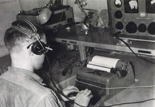 |
| ABRS Spud Roscoe copies a message from the SP600 receiver in the Radio
4 aboard HMCS SWANSEA in January 1961. Note the chain which holds down
the typewriter in case of heavy seas. Pictures such as this were forbidden
by the RCN. (Photo courtesy Spud Roscoe) |
When a CS/RS operator terminated his duties permanently, he went through
a "deindoctrination" process which included signing documents relinquishing
SECRET 'CODEWORD', TOP SECRET, SECRET, and CONFIDENTIAL knowledge and a
promise never to divulge such without clearance from the Minister of National
Defence. In 1952, a few CS operators were collected from various stations
around the country to take a course in RCM (Radio Countermeasures) and
RADCM (Radar Countermeasures) after which they were dispatched to HMC Dockyard,
Halifax. These ratings were not allowed to explain their duties, had to
be secretive, and couldn't tell anyone the ships they were boarding. (They
didn't even know themselves). They were simply not welcome in the dockyard.
What most people didn't know was the reason for their presence - to be
involved in the Canadian development of the UPD501 and its operational
tests.
Ray White, Chief Petty Officer 2nd Class RCN (Retired), was CS rate
and provides some comments on one aspect of his service. "During my time
in the RCN, there always was a demarcation line between "us", the guys
behind the green door, the keepers of the secrets and the spies. We didn't
really feel as if we were members of the 'Sparkers' community. When small
numbers of the CS branch went to sea in the Radio Warfare specialty, the
Sparkers realized that we did indeed have skills that meshed with
theirs. As a group, we had superior Morse Code copying abilities, especially
under difficult conditions. We never had the luxury of asking for
repeats, for example, when copying target transmissions. So we worked
harder to get it right. On the other hand, most CS rates were not well-versed
in Morse transmitting. As a group, the acquisition of a Sparker's "fist"
was just unheard of".
It took almost ten years to convince the captains of vessels to rely
on Radar, yet, when the CS/RS personnel showed up aboard ship, they requested
that the Radar be shut down because it jammed the 'D/F' and also gave away
the position of the ship! It probably took another ten years to reverse
this thinking.
In 1953, electronic warfare rooms were also installed in HMCS Huron
and Iroquois for operations in the Korean theatre and each had a CS operator
(P/O or L/S of a high Trade Group) drafted on board. There is an incident
worth relating about secrecy. On HMCS Iroquois, the new CS op was just
drafted but not informed about the protocol of a CS being introduced to
the CO. The following day, the Commanding Officer was making his rounds
of his new ship and told the Executive Officer that he wanted to inspect
Radio 4. Upon hearing this, the CS operator refused to let the CO or XO
climb the ladder to Radio 4 and immediately dashed up the ladder to padlock
the door. Furious, the CO had him thrown off the ship onto the jetty with
all his kit. This was three days before sailing time to the Korean war.
Next day, a three-ring commander arrived in Halifax and gave the CO his
indoctrination, however, the poor CS was never the most popular person
in the eyes of the CO ever again.
The policy of having the CO indoctronated prior to being given access
to Radio 4 was not a consistent one. For instance, when Spud Roscoe served
aboard HMCS Swansea in Radio 4, he was told to simply throw a cover
over top of anything that he was working on if the captain wanted access
to Radio 4. In fact, Spud invited the Captain into Radio 4 to listen
to Russian music broadcasts because he liked that genre of music
Since Radio 4 was considered a top security area. The door was labelled
with a sign warning one of this fact and it was always kept locked up when
not in use. Since access was so restricted, it was also a good place to
catch up on lost sleep. This wasn't so bad considering these CS/RS ratings
copied CW at 35 WPM in languages such as plain language English, plain
language foreign and Kata-Kana ".
Please refer to the Communicator Supplementary and Radioman Special
Branch document in the Table of Contents for more information on CS/RS
rates.
A log of Radio 4 restoration activities
can be found here.
Credits and References:
1) Curt Bowles <curt.bowles(at)gozoom.ca>
Back to Table of Contents
Jan 20/26