 |
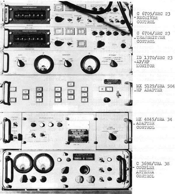
| AN/SRC 502 - RADIO TRANSMITTER-RECEIVER GROUP (Image courtesy
Canadian Navy )
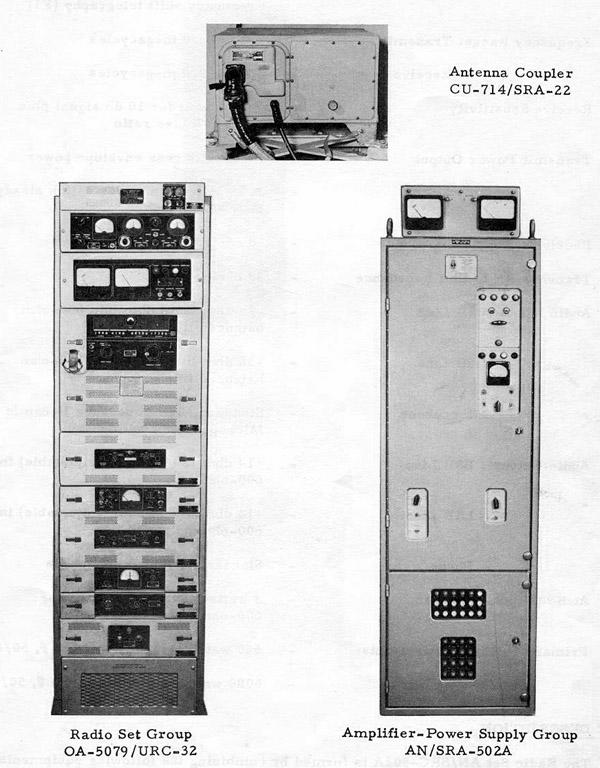
---------------------------------------------------------------------- Purpose - General purpose HF transmitter/receiver.
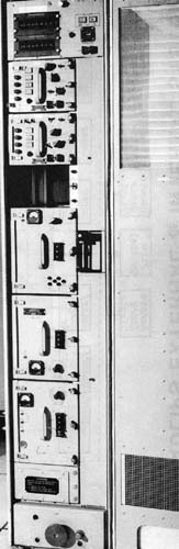
Brief Description - During transmission, the Radio Set Group OA-5079/URC-32 generates an RF carrier and provides facilities to modulate or key this carrier with an input signal. The modulated or keyed RF carrier is amplified by the Amplifier-Power Supply Group AN/SRA-502A and then fed via the Antenna Coupler AN/SRA-22, to the antenna. During reception, the RF signal received at the antenna is fed via the Antenna Coupler AN/SRA-22 to the Radio Set Group OA-5079/URC-32, where it is amplified and demodulated. The demodulated signal is fed to a local handset or to remote signal lines. CONSISTING OF: OA-5079 AN/URC 32 - HF TRANSMITTER- RECEIVER
Major Units - Interconnection Box - contains main power & connecting cables.
Amplifier Converter Modulator - Translates AF to IF during TX and IF
to AF during receive.
AN/SRA-502 RF Amplifier
Full Description : AMPLIFIER-POWER SUPPLY GROUP AN/SRA-502A
1 Amplifier, Radio Frequency AM-5155/SRA-502A
Specifications: * Bandwidth: 1. 5 to 24.0 megacycles
* Power Input Levels (Signal) (a) Single tone: 28 milliwatt input for 700 watts mean power output
* Power Outputs: (a.) 1000 watts peak power when used with a single exciter for Al or
A3a transmission
* Input Impedance: 75 ohms (50 ohms with RF input adapter)
*Primary Power Requirements: 6000 watts, 380/450 volts, 50/60 cps, 3
phase
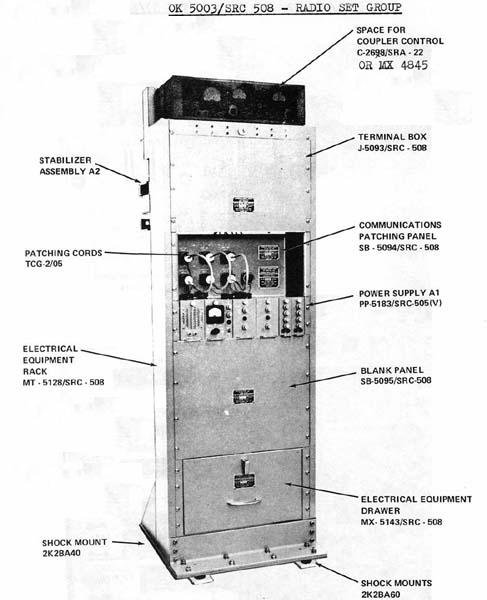
All units, except the Indicator Panel, are housed in a shock-mounted
steel cabinet, which is horizontally divided into two compartments, each
with its own door and lock. The upper compartment contains' the RF amplifiers
and controls, and the lower compartment contains the power supplies and
the power transformer. The RF amplifiers and the power supplies are mounted
on heavy-duty runners. Operating controls, fuses, indicating lights and
a panel meter are accessible through cut-outs in the doors. Air inlet and
exhaust ducts, and cable entries s are provided on the cabinet top. The
indicator panel is mounted on the cabinet top and is angled towards the
operator.
The AN /SRA-502A is a two stage RF amplifier with its own built-in power supplies. Both stages of the RF amplifier section are balanced distributed amplifiers, which utilize transmission lines to feed the grid circuits and as the plate loads. The first (penultimate) stage is RF Amplifier AM5156/SRA-502A, which has 9 pairs of JAN 6688 tubes working in push-pull operation. It amplifies the RF input signal to the required level to drive the final stage. The final stage is RF Amplifier AM-5155/SRA-502A, which has 8 pairs of 4CX250B air-cooled tubes working in a linear form of class AB1 push-pull operation. The output of the final stage is applied through a directional coupler to the antenna system. The directional coupler contains three probes, which feed samples of forward and reflected power to the indicator panel, which continuously monitors power output and VSWR. Power Supply PP-S140/SRA-502A and Transformer TF-5005/SRA-S02A supply the plate voltage to the final stage. The remaining operating and control voltages are provided by Power Supply PP-5139/SRA-S02A. Heating elements are fitted in the cabinet base to provide means of drying out the equipment when operating under conditions of high humidity. A common metering instrument, in conjunction with five metering circuits, may be switched to read all of the internal DC supply voltages and to monitor the various check points in the equipment. Air flow and door safety interlock circuits are incorporated. CONTROL CIRCUITS Controls on the AN/SRA-502A are reduced to those necessary for applying supply voltages and for routine metering. No tuning is necessary after the initial "setting-up". Panel indicator SP-5053A/SRA-S02A may be used to control the equipment from a remote location. REMARKS The AN/SRA-502A is the Canadian equivalent of the British built AN/SRA-502.
|
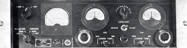 |
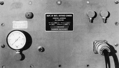
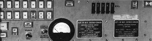
| ANTENNA COUPLER CONTROL CU-2698/SRA-22 (Image courtesy Canadian
Navy)
Antenna Coupler Group AN/SRA-22 is used to couple the AN/SRA-502A either to a long wire antenna or to a 35-foot whip antenna and provide 50 ohm matching. This panel connects to the CU-714/SRA-22 Antenna Coupler which is in a water-tight enclosure and is mounted at the base of the antenna. Frequency Range: 2 to 30 MHz
BRIEF TECHNICAL DESCRIPTION The AN/SRA-22 is primarily a tuned circuit, in which the coil inductance, the coil tap and the capacitance are variable.The coil is formed by a silver ribbon wound on two drums, one metal and the other ceramic. The inductance of the coil is varied by winding the silver ribbon from one drum to the other. Maximum inductance is obtained when all the silver ribbon is wound on the ceramic drum. The drums are motor driven. The coil may be tapped at any point on the silver ribbon by varying the position of a motor driven contact.The motors for the coil and tap drives are controlled by sending-potentionmeters and null-position indicators on the Coupler Control and by receiving-potentionmeters on the Antenna Coupler. The capacitor is a variable vacuum type and is positioned by a motor drive which is controlled by a 12 position switch. The capacitor may be switched in parallel or in series with the antenna. A wattmeter on the Coupler Control may be switched to indicate forward or reflected power. Manual : NAVSHIPS 93286 |
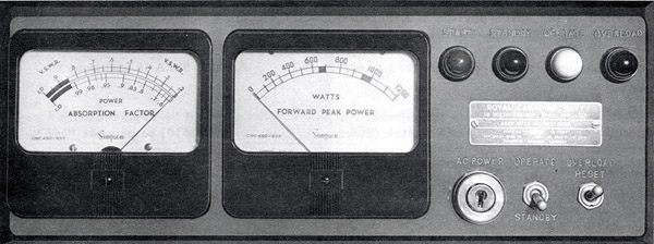 |
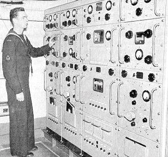
| SB5053A/SRA-502A Stock No. 5820-21-041-5216. Part of the AN/SRA-502
RF amplifier. This remote-control unit is used to control the AN/SRA-502A
Amplifier-Power Supply Group from a remote location and to provide indication
of the VSWR and power output of that equipment.
When the SB-5053A/SRA-502A is used as a component part of Radio Set AN/SRC502A, it is mounted on a hinged frame assembly and enclosed in a Cover Assembly. The complete assembly is mounted on the upper portion of Electrical Equipment Rack MT-2092/U, which is part of Radio Set Group OA-5079/URC-32. Except for the type of meters used, the SB-5053A/SRA-502A is identical to SB-5053/SRA-502. On RCN installations the normal AC power switch is replaced with a key operated Rotary Action Lock Switch to provide "MAN ALOFT" functionality. (Image courtesy Canadian Navy) |