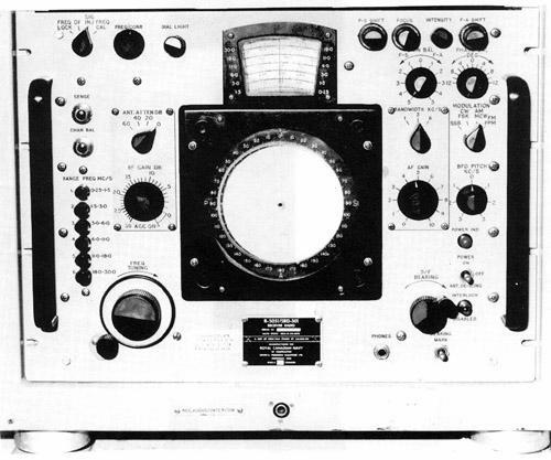
The AN/SRD-501 was acknowledged to be a piece of absolute junk
by those who used it.
It was a hybrid unit with tubes on the lower deck and solid state on
the upper deck (and yes, heat does rise). It was impossible to reach sensitivity
or calibration specifications because immediately that the case was opened
or closed the ambient temperatures changed and the operating parameters
changed. Usually the SRD was never turned off because once it cooled down
and then flashed up, it required a complete IF alignment!
No end of "UCRs" (unsatisfactory condition reports) ever brought a resolution
to the ensuing problems. The specifications were changed so that a 20 µv
sensitivity was acceptable. One technician said "When I was personally
responsible for this equipment, I ensured that I got maximum sensitivity
and selectivity for 500 kHz and 2182 kHz and hoped it did well for everything
in between".
|
|
R5051/SRD-501 DF set. (Image courtesy Canadian Navy)
|
A detailed list of AN/SRD-501 problems
can be found here.
Reference: https://nrc-publications.canada.ca/eng/view/fulltext/?id=1a97eb24-45af-4668-a63d-dd8627547b08
SPECIFICATIONS:
* Frequency range: 60 kHz to 30 MHz
* Modes: AM, FM, FSK, CW, SSB, PPM
* Accuracy: +/- 1 to 2 degrees with a range up to 70-80 miles
on ground wave only. Not
accurate on sky waves. Obtaining the sense, (boiling out ambiguity)
was difficult above 6 MHz.
This unit contains two receivers and was used by EW personnel to determine
the bearing of any transmitting station within its range.
* IF Freq: 500 kHz (which was known to re-radiate).
* Antenna type: AS 5039
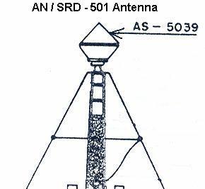 |
| The AN/SRD-501 was initially fitted to the 205 class ships except Assiniboine.
(Graphic courtesy Canadian Navy) |
AN/SRN-12
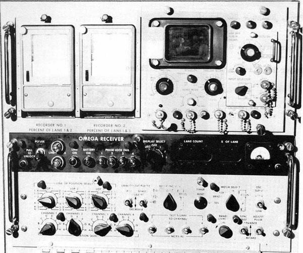 |
| AN/SRN-12 Omega Receiver which was used for obtaining a radionavigation
fix from the now defunct Omega
system which survived until 1997. Accuracy was +/- 2 nm at distances
of 8,000 nm. (Image courtesy Canadian Navy) |
LC 204 LORAN RECEIVER
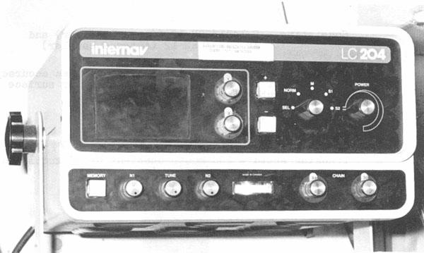 |
| INTERNAV LC 204 LORAN 'C' RECEIVER . (Image courtesy
Canadian Navy) |
AN/URN-20A (V)1 TACTICAL AIR NAVIGATION
 |
| AN/URA-20 TACAN is a polar-coordinate type radio air navigation system
that provides an aircrew with distance, bearing and identification information.
It can simultaneously provide individual distance
measuring service for up to 100 interrogating aircraft.
(Image
courtesy Canadian Navy)
The signal transmission is a priority sequence and is always done in
the following order:
1. AZIMUTH , or a corrected magnetic bearing to the beacon, is a continuous
output and services an unlimited number of aircraft.
2. IDENTITY of the beacon, which is transmitted in international Morse
Code at 37.5 second intervals with a duration of 5.5 seconds.
An unlimited number of aircraft can be serviced.
3. DISTANCE to the beacon in nautical miles, which is done on an interrogation
basis, and services 100 aircraft maximum, by selecting the closest 100
aircraft. The distance measuring concept used in TACAN equipment is an
outgrowth of radar-ranging techniques; i.e., determining distance by measuring
the round-trip travel time of pulsed RF energy. The return signal (echo)
of the radiated energy depends on the natural reflection of the radio waves.
However, TACAN beacon-transponder facilities, located at specific geographic
positions, generate artificial replies rather than depending upon natural
reflection. The airborne equipment generates timed interrogation pulse
pairs that are received by the surface TACAN system and decoded. After
a 50 µsec delay, the transponder responds with a reply. The round
trip time is then converted to distance from the TACAN facility by the
airborne DME.
4. SQUITTER; a filler pulse train, which automatically keeps the Pulse
Repetition Frequency Constant by adding pulses to the train as required. |
In the X mode of operation, the
TACAN set transmits on one of 126 discrete channel frequencies
(which are 1 MHz apart) from 962 to 1024 MHz and
from 1151 to 1213 MHz. In the Y mode of operation, the set
transmits on one of 126 discrete channel frequencies (which
are 1 MHz apart) within the range of 1025 to 1150 MHz. The
navigation set receiver, operating in the
1025 to 1150 MHz range for both the X and Y modes, is
always displaced 63 MHz from the transmitter frequency.
Of the 3,600 pulse pairs-per-second transmitted by
the TACAN, 900 pulse pairs (MAIN and AUXILIARY bursts) contain
the bearing information; the remaining 2,700 pulse
pairs are either random noise pulses, identity pulses, or replies
to interrogating aircraft. Once every 30 seconds, the
interrogation replies and random noise pulses are interrupted for
the transmission of identity pulses. The navigation set has a receiver
sensitivity of -92 dBm or better and a nominal peak power output of 3 kilowatts
at the transponder cabinet output. Power output
may limited to less than peak by directives. Since the bearing and identification
signals are delivered spontaneously and not in response to interrogations,
an unlimited number of properly equipped aircraft can derive this information
from the TACAN set over a line-of-sight (los) range up to 200
nautical miles.
AN/URN-20 SPECIFICATIONS
Power Output: 50 watts average; up to 10 KW average peak
Power Requirements:
440V 60 Hz 3 phase for the antenna
440V 60 Hz for the transmitter.
115V 60 Hz for the Low Voltage Power System, test equipment and
blower fans.
Maximum Range : - 200 NM slant range.
Antenna Rotation:- 900 RPM
Pulse Repetition Frequency: 7200 PPS or 3600 PPS
Pulse Spacing: 12 usec
System Delay: 50 usec
Frequency: 962 to 1213 MHz
Klystron Beam Voltage - neg 20 KV
Klystron Bean Current : variable 0 to 100 MA, 50 ma optimum
setting
Manufacturer: ITT Avionics Division, Nutley. N.J.
Contract Number: NOOO39-68-C-2558
Manual Reference: BRCN 4429(1)
Vintage: believed to be around 1968
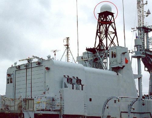 |
| On Canadian ships which were fitted with dome shaped TACAN antenna
there were two possibilities for the antenna mounting. 1) It was mounted
a pole mast aft of the foremast. 2) In the case of Fraser (shown above),
it was fitted atop a lattice tower between the funnels (in 1987). (Photo
by Jerry Proc) |
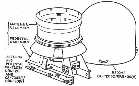 |
| AS-1747/URN-20(V) antenna internal view. The antenna and pedestal are
enclosed in a glass fiber reinforced plastic protective radome. The antenna
central array, spin motor, rotating assembly, and bearing control servo
assembly are mounted on a single base in the pedestal assembly. This base
is maintained in a horizontal plane by a roll servo system. (Image and
copy courtesy Combat Index Home Page)
Specifications:
Physical Dimensions: 54.5" H; 65 inches diameter
Weight: 480 lbs
Operating Temperature -28 C to +95 C
Frequency Range: Transmit: 962 to 1024 MHz
Receive: 1025 to 1150 MHz
Input Impedance: 50 ohms (nominal) VSWR > 2:1 over frequency
range
Polarization: Vertical
RF Power Rating: 20 kilowatts at 2% duty cycle.
Power Requirement 115 VAC, 60 Hz., 1 phase for convenience outlet.
All other power and control voltages are supplied from the amplifier group.
Feed Type: Unbalanced, coaxial cable
Input Connector Type C
Caveat: The cable lengths between the antenna and amplifier group must
not exceed 200 feet. |
AN/URN-25 TACAN
 |
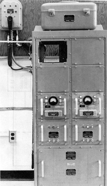
| The AN/URN-25 TACAN Transponder Group is a full service transponder,
providing TACAN-equipped aircraft with range, bearing, and identification
within a 300 nm radius. This navigation aid was fitted to Annapolis 266
and the 280 class ships. It is currently used in the Halifax class patrol
frigates. Pictured above is a dual installation with automatic switchover
to the standby unit in case the primary unit fails. In between the transponders
is the control unit. (Photo and specifications courtesy NavCom Defence
Electronics) |
FEATURES:
* All solid state except for the ceramic triode tubes in the transmitter
output stage.
* All band capability X and Y mode. 252 channels available.
* Emergency power levels of 700 and 150 watts available in case of
transmitter tube failure
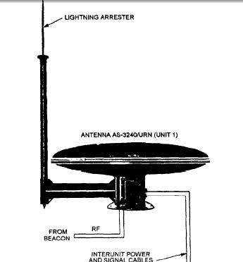 |
| OE273/AS3240 TACAN antenna. Nothing spins in this antenna. All elements
are controlled electronically. (Image courtesy Global Security
web page) |
SPECIFICATIONS:
Major Units: Transponder Group OX-52/URN-25 and the Control-Indicator
C-10363/URN-25
Transmitter: Power output: 3,000 watts at end of tube life.
700 watts reduced power mode (selectable)
700 and 150 watts for emergency power level.
Antenna Group: OE-273A(V)/URN / AS3240
Power Input: 115 volts 45 Hz to 450 Hz.
Weight: Transponder - 960 lbs( 436 kg)
Status Control Indicator - 75 lbs (34 kg)
Dimensions : Transponder Cabinet only - 66" H x 26" D x 24" W
Manufacturer: NavCom Defence Electronics.
El Monte, California
SAMPLE BLOCK DIAGRAMS OF VARIOUS SYSTEMS
Click to enlarge
|
|
 |
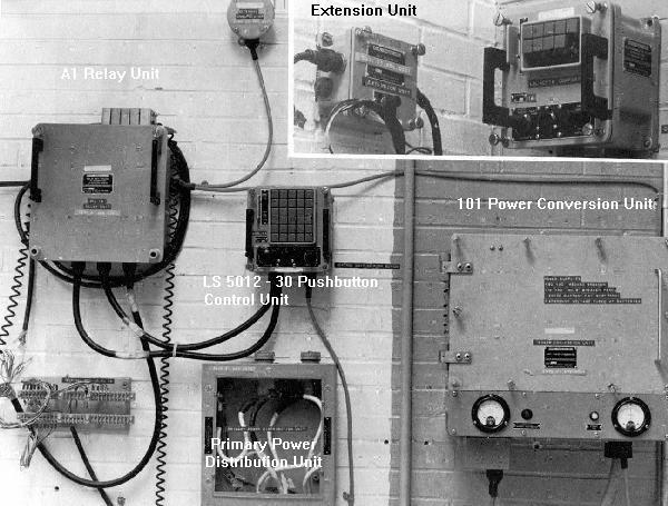
AN/SIH-503 Main broadcast system as fitted
in the ISL class. (Diagram courtesy Canadian Navy) |
 |
Frequency Standard System. This 280/AOR
class block diagram shows how the signal from the HP 5061A cesium beam
standard is applied to the SRC-23 device as a reference. The outputs of
the two 1107 frequency standards are then compared to the cesium beam standard
and automatically adjusted.
Two 100 kHz signals then leave the SRC-23 and are applied to the input
of the distribution amps. Outputs of the distribution amps are then connected
to the SB 5091/SRC patch panel for distribution to the various HF,
VHF and UHF transceivers throughout the ship. (Diagram courtesy Canadian
Navy) |
 |
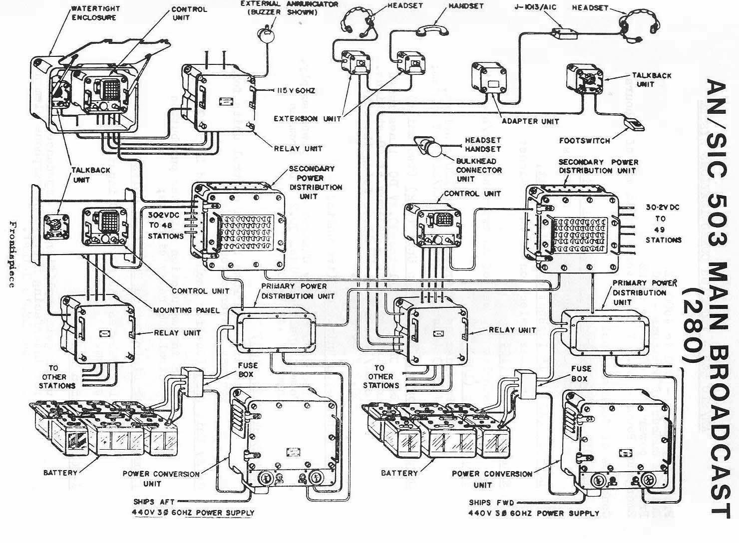
AN/SIC-503 Main Broadcast for a 280 class
ship. This pictorial illustrates all of the system components. (Diagram
courtesy Canadian Navy) |
 |
AN/SRC-507 Flight Deck Broadcast System.
This was only fitted in ships with helicopters. (Image courtesy Canadian
Navy)
R5061/ SRC-507 (2 on each ship)
----------------------------------
Battery operated FM receiver enclosed in a helmet.
Frequency Range: 132 - 150.8 MHz
Operates at 139.04 MHZ.
T5054/SRC-507 (2 on each ship)
Battery operated FM transmitter enclosed in a handset.
Can be used. with the fitted antenna or with the AT 1086 whip antenna.
Power output 5 milliwatts.
Frequency Range: 132 - 150.8 MHZ
Normally operates at 139.04 MHz
AT 1086/SRC 22 (one on each ship)
-------------------------------------
Omni directional whip antenna that may be connected to the T5054 handset.
Normally fitted outside just above hangar door.
PP 3221/SRC 22 (one on each ship)
-------------------------------------
Battery charger for receiver and transmitter batteries. Holds 20 Batteries.
MX5150/SRC-507 (one on each ship)
---------------------------------------
Handset holder for holding two handsets.
TS 100A TEST SET ( one on each ship)
-----------------------------------------
Used to test the helmet receiver and handset transmitter. |


