K649 MuFAX
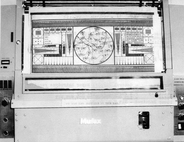 |
| K649 MuFAX. The machine appears to have produced a test pattern. Note the sign on the front lip of the machine " DO NOT LIFT MACHINE BY THIS BAR". (Photo courtesy Canadian Navy) |
R1051-B RECEIVER
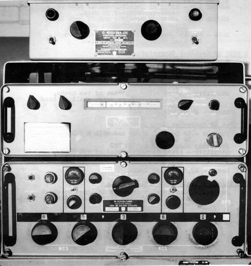 |
| Top - C6193/SRA 17C Antenna Control Panel for LF Probe
Middle - CV 5086/URR LF Converter Bottom - R1051B/URR Receiver (Images courtesy Canadian Navy) |
The RCN used the 'B' model of this receiver. HMCS Huron DDH 281 and the other ships in her class had twelve R-1051's aboard according to an RCN inventory list circa 1985. .
Later variants such as the R-1051G and R-1051H, are fully solid state and look somewhat different.
Specifications:
* Frequency Range : 2.0 to 29.9999 MHz in 0.1 khz increments, or 2.0
to 30.0 MHz with continuous vernier
tuning between 100 Hz increments.
* Receiver Type : Superhetrodyne (triple conversion)
* Frequency Stability : 1 part in 10 to the 8th per day
* Frequency Accuracy : plus or minus 0.5 Hz at 5 MHz
* Type of Frequency Control : crystal controlled synthesizer referenced
to a 5 MHz internal or external standard.
* Modes of Operation : LSB, USB, ISB, AM, CW, and FSK
* Sensitivity : 1 uV for 10 dB (S + N / N) in SSB mode ; 2 uV in CW
and FSK modes ; and 4 uV in AM mode
* Receiver IF : first, 20 or 30 MHz ; second, 2.85 MHz ; third, 500
KHz
* Bandwidth : SSB, 3.2 KHz ; AM, CW and FSK 7 KHz
* Recommended antenna : 50 ohm impedance
* Power consumption : 55 watts
* Primary power requirements : 115 VAC plus or minus 10%, single phase,
at 48 to 450 Hz
* Weight : 70 lbs
* Dimensions without mounting brackets or shockmount : 17 3/8 inches
wide ; 7 inches high ; and 19
inches deep
* Manufacturer: Originally designed by Bendix.
* Vintage: March 1968
* Reference: NAVSHIPS 0967-970-9010; RCN C-51-158-000/MS-000 and MC-000
* RCN Stock #5820-00-948-3408
BRIEF TECHNICAL DESCRIPTION
Signals received from the antenna are coupled to the antenna tuning circuit in the RF amplifier module by an impedance matching network. Two stages of RF amplification combined with four digitally tuned selective circuits, provide an amplified RF signal in the 2.0 to 30.0 MHz range.
The Translator/Synthesizer module performs the translation from the RF to the IF utilizing injection frequencies provided by the synthesizer, and locked to the frequency standard with a stability of one part in 10^8 per day.
The Mode Selector module contains the diode gates for switching the USB, LSB, and AM (double sideband) mechanical filters for the desired mode of operation. This module also contains the BFO circuitry required for CW reception.
Independent side band reception is provided by the use of two separate IF / Audio modules. Each of these units provides IF amplification, detection, and audio amplification. The incoming signal is processed by the one module appropriate to the particular signal mode except when both sidebands of ISB are being received.
The frequency range of the R1051 can be extended down to the VLF band
by using the AN/SRA-17 low frequency probe antenna (14 - 600
KHz) and the CV-5086/URR low frequency converter ahead of the receiver.
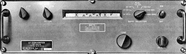 |
| CV-5086/URR Frequency Converter. (Image courtesy Canadian
Navy)
BRIEF TECHNICAL DESCRIPTION The RF signal from antenna is filtered and applied to an antenna overload
circuit which shorts the RF signal to ground whenever the amplitude exceeds
a preset value. The output from the antenna overload circuit is amplified
and applied to Diode balanced modulator circuit which also receives the
5 MHz standard frequency from the associated R1051B receiver.
Physical: Height 5-7/32 inches; Width 17-3/8 inches; Depth 18-7/8 inches
|
R-5099/U (Collins HF 2050) RECEIVER
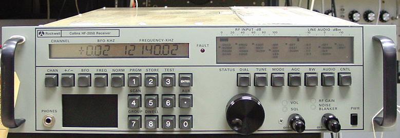 |
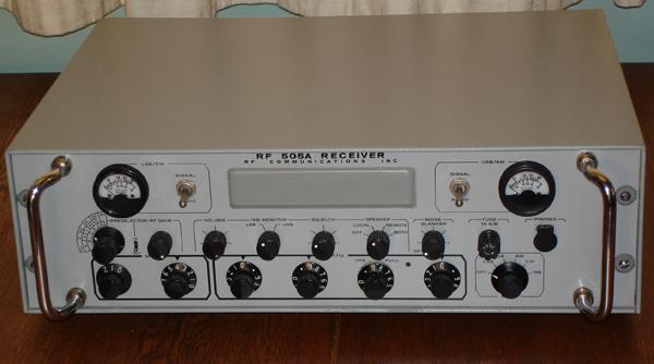
R-5099/U receiver. Click to enlarge. The serial number on this unit is 86-0777. (Photo courtesy Toronto Scientific and Surplus) |
Designed by Rockwell-Collins, Cedar Rapids, Iowa and built by Rockwell-Collins Canada (Toronto) for the Canadian Department of National Defense, the HF 2050 was known by the following military designators: R-5099/U, R-5099A/U, and R-5104/GRC-508. Made between 1984 and 1991, it was the last receiver built by the Collins plant in Toronto before shutting down and was also the world's first DSP receiver. In many ways, it was far more advanced than anything available at the time.
The R-5099 units have a gray front panel while the R-5104 Army version was destined to have a beige panel. No examples of this variant were ever seen on the surplus market. The Canadian Navy was one of the end users of the receiver and the remainder were used by other military customers such as the Canadian Army.
According to Walter Salmaniw of Victoria, BC., "the total production run was somewhere in the neighbourhood of 1,154 units, with virtually all of them going to the Canadian military. There were efforts made to sell abroad and four receivers made it to Israel. I was on-board HMCS Huron DDH-281 just as the navy was transitioning from the HF-2050 to the Harris RF-590 receiver. The radio room had a stack of seven or eight 2050's, and as I recall there were a couple more elsewhere on the ship. The only problem with the 2050 is the lack of proper power supply cooling. Without a fan retro-mounted on top of the chassis, the temperature inside the chassis can easily reach over 180 deg F. Overall, the 2050 continues to be an incredibly reliable machine as long as the power supply is kept cool with fans".
Other users have reported less-than-optimal tuning rates. A photo of an acceptance tag indicates a date of Feb 25, 1988. The DND stock number for the R5099/U is 5820-21-895-6263. Collins identified this receiver as part #622-6577-002.
Gus Davidson provides some figures which illustrate the deployment of
the R-5099 receiver in the RCN.
"The Met shack and EWCR also had a couple and I know the 280's and
IRE's had more than their share of anyone else. The table below provides
details on deployments on 26 ships and submarines subs, 2 shore stations
including transmit sites, 3 nodes, 2 concentrators, 2 training schools
and 2 Command HQs. The rest went to the Army for their HF Comms, and Comm
Squadrons and some were deployed to the RCAF for use aboard the Aurora
aircraft".
| MACKENZIE 14
SASKATCHEWAN 14 QU'APPELLE 14 YUKON 14 Total =56 |
GATINEAU 18
KOOTENAY 18 RESTIGOUCHE 18 TERRA NOVA 18 Total=72 |
NIPIGON 14
ANNAPOLIS 14 SKEENA 14 FRASER 14 OTTAWA 14 SAGUENAY 14 Total=84 |
| PROVIDER 12
PROTECTEUR 12 PRESERVER 12 Total=36 |
HURON 18
ATHABASKAN 18 IROQUOIS 18 ALGONQUIN 18 Total=72 |
CORMORANT 6
SUBS 3-4 EA Total=16 |
| MARPAC OPS COMMCEN 8
MARCOM OPS COMMCEN 10 Total=18 |
CFFS (E) 8
CFFS (H) OPERATIONS TRAINER 10 CFFS (H) TECHNICAL TRAINER 10 Total=28 |
ALDERGROVE/MATSQUI-20
MILL COVE/NEWPORT CORNERS 20 Total=40 |
| 2 Concentrator Sites:
NANAIMO 10 EAST COAST /(CARP?) 10 Total= 20 |
Each ship that had 2050's fitted also carried at least one complete unit as an onboard spare. Add another 22 for ships (no subs). | 3 Node Sites:
DEBERT, PENHOLD, TRENTON. 10 at each site Total=30 |
|
|
||
SPECIFICATIONS:
Modes of operation: CW, AM, USB or LSB, (ISB optional), and FSK (with
external modem)
Frequency range: 14 KHz to 29.999 99 MHz in 10 Hz increments.
Frequency stability: Less than +/- 1 x 10E-8 at 0 to + 50 degrees C.
Drift rate of not more than 3x 10E-8 per month.
Channeling speed: 50 ms maximum
Preset channel memory: 30-channel capacity initially. Each channel
contains frequency, mode, bandwidth, AGC, and BFO information. Later versions
of the software permitted the expansion of preset memory from 30 to 100
channels.
Sensitivity (SSB): 14 KHz to 500 KHz: 2.5 microvolt for 10 dB (s+ n)/n.
500 kHz to 29.999 99 MHz: 0.82 p V for 10 dB (s+ n)/n.
Image rejection: 80 dB minimum.
Speaker: 2.5 watts peak into 8 ohms; maximum 5% distortion
Bandwidths: 2.80-KHz USB/LSB/ISB; 0.3-KHz, 1.0-KHz CW; bandpass
filters 3.2-KHz; 6.0-KHz AM bandpass filters.
Antenna input impedance: 50 ohms nominal, unbalanced 2:1 VSWR
maximum for 2.0 to 29.999 99 MHz
Power requirements: 115 V ac +/- 10%, 47 to 63 Hz, single-phase ac;
100 W nominal
Enclosure: 19" rack is standard. It can also be mounted in a desk-top
enclosure or in a console.
Environmental Temperature: Full performance: 0 to +50 degrees C (+32
to +122 degrees F).
Physical Size: 5.25 in high x 19 in. wide x 19. 6 in deep
with handle
Weight: 17.2 kg (38.0 lb) maximum.
RACAL URR-502A (R 5032)
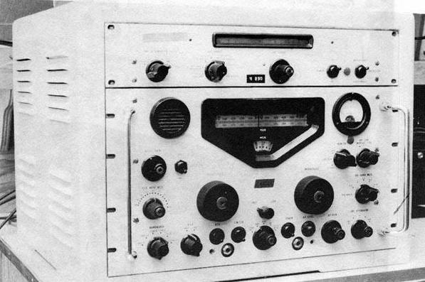 |
| Racal URR-502A LF/MF/HF Receiver with the CV-5046/URR LF converter above it. The URR502A is a basic URR501 fitted with the CV 5046 low frequency converter and both in a common cabinet.(Photo courtesy Canadian Navy) |
BASIC RECEIVER SPECIFICATIONS
Frequency Range - 980 KHz to 30 MHz (will tune down to 500 KHz with
a slight reduction in sensitivity).
Stability - After warm-up period of two hours, overall frequency drift
shall be less than 50 Hz.
Modes -AM, CW, MCW, FSK, FAX.
Power Requirements: 100/125 VAC or 200/250 VAC 45/65 Hz. 85 watts .
Single phase.
RCN stock #5820-21-804-2324
TERMINOLOGY FOR THIS RECEIVER
R 5032 is the basic HF Receiver
CV 5046 is the LF Converter.
AN/URR 501 - R5032 HF receiver mounted in a rack.
AN/URR 501A- R5032 HF Receiver mounted in cabinet
AN/URR 502 - R5032 HF Receiver and CV 5046 LF converter mounted in
rack.
AN/URR 502A- R5032/URR HF Receiver and CV 5046/URR LF converter
mounted in cabinet CY-5099/URR.
Dimensions: 16" H x 20.5 "W x 22" deep.
Weight: 100 pounds
Applicable manuals : BRCN 4265
The Racal name derives from the receiver's two designers who were RAymond Brown and George CALder (Jock) Cunningham.
BASIC OPERATION
The Receiver R-5032A/URR is a triple superheterodyne receiver employing electronic band-switching in steps of 1 Mc. Fine tuning is accomplished by means of a very stable interpolation receiver covering a spectrum of 1 Mc. A 60-inch film scale is provided, accurately calibrated in 1 kc divisions (kilocycles dial). A number of audio and IF outputs are provided and a small loudspeaker is fitted for monitoring purposes.
Input signals are applied through an antenna attenuator to the RF amplifier; they are amplified and passed through a low pass filter to the first mixer. Here the input signal is mixed with the output of the first VFO which may be tuned between 40.5 and 69.5 Mc. The output of the first mixer is a 40 Mc first IF which is fed through a band pass filter to the second mixer. At the second mixer the 40 Mc IF is mixed with a 37.5 Mc frequency to produce a 2 to 3 Mc second IF. Harmonics from a 1 Mc crystal oscillator are mixed with the first VFO output and passed through a filter to obtain the 37.5 Mc frequency. The second IF is applied through filters to the third mixer where it mixes with the output of the second VFO to obtain the third IF which is 100 kc. The signal is amplified in a 100 kc IF amplifier strip and then demodulated in a detector stage. The demodulated signal is further amplified by an AF amplifier and then fed to the various receiver outputs.
A crystal calibrator, controlled by the 1 Mc crystal oscillator, provides
100 kc check points for the second VFO.
Noise limiting, AVC and VFO stabilization circuits are incorporated;
and a BFO is provided for CW reception. The receiver is operated locally,
or may be operated remotely by a suitable remote control unit.
CV-5046/URR LF CONVERTER
Frequency Range - 10 to 980 KHz
Stability - After warm up period of two hours, overall frequency
drift shall be less than 50 Hz.
Modes - AM, CW, MCW, FSK, FAX
Power Consumption : 100/115 VAC or 220/250VAC, 45/65 Hz. 11 watts (for
tube heaters)
The components of the converter are mounted on a front panel and main
chassis assembly which is suitable for rack mounting, or mounting into
cabinet CY-5099/URR.
All operating controls are located on the front panel. External cabling
is connected at the rear of the main chassis.
The equipment measures 3-1/2 inches high by 19 inches wide by 13 inches deep and weighs 13 lb.
BRIEF TECHNICAL DESCRIPTION
The RF Converter is basically a frequency convertor which raises the frequency of incoming signals by 2 Mc. Wide band or tuned amplification may be selected. Internally , the circuits an RF amplifier and filter, a harmonic generator and filter, a mixer stage and a cathode-follower output stage.
Incoming signals are amplified by the RF amplifier and fed to the mixer. A 1 Mc frequency from the receiver R-5032A/URR is used to excite the harmonic generator which provides an output of 2 Mc. This 2 Mc frequency is mixed with the received signal in the mixer stage. The output of the mixer is a signal in the frequency band from 2.010 to 2.98 Mc. This signal is fed to the cathode-follower output stage. The output from the convertor is fed to Receiver R-5032A/URR. When operating in the VLF/LF Band the convertor replaces all stages of receiver R-5032A/URR prior to the second IF amplifier. The converter requires an antenna system separate from that provided for the associated receiver.
Applicable Handbook: BRCN 4265