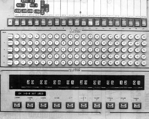
C 5205/SRA-504
Control indicator for DDH 280 designed to accept 20 transmit/receive
circuits and provide a ready/busy status indicator for the TX section of
these circuits. In addition, any of the 10 circuits can be allocated to
the 10 channels of the Control Radio Set. It also allows any one of the
20 transmit/receive circuits to be switched into any of the 5 monitoring
positions.
C 5206/SRA-504
Control indicator for the AOR is designed to accept 10 transmit/receive
circuits and provide a ready/busy indicator. In addition any of the 10
circuits can be allocated to the monitoring position.
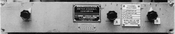
SA 5042/SRA-504
Matrix signal routing switch providing the capability of connecting
10 six level inputs to any of 10 six level outputs. (Not shown)
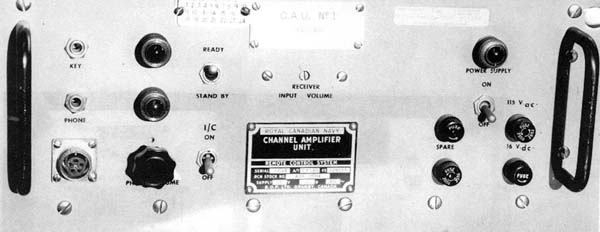
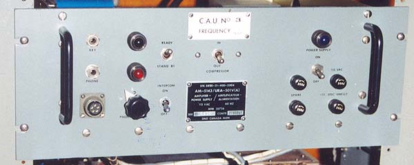
OG 5001/SRA-504
Amplifier Power Supply Group (APS) provides the following functions:
a) amplifies the received signal to drive the CRS.
b) while transmitting, provides a side tone for the CRS.
c) Presence of keyline voltages is detected and "Ready" indicators
are energized.
d) Operation of a PTT switch or key connected to the circuit is detected
and the associated transmitter is keyed as well as the "Busy" indicator
is illuminated.
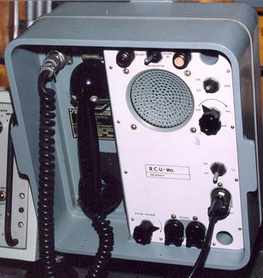
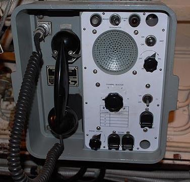
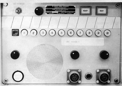
C 5207/SRA-504
Control Radio Set (CRS) permits the remote operator to obtain access
to anyone of ten communications channels available from the associated
matrix.
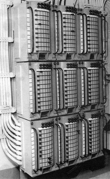
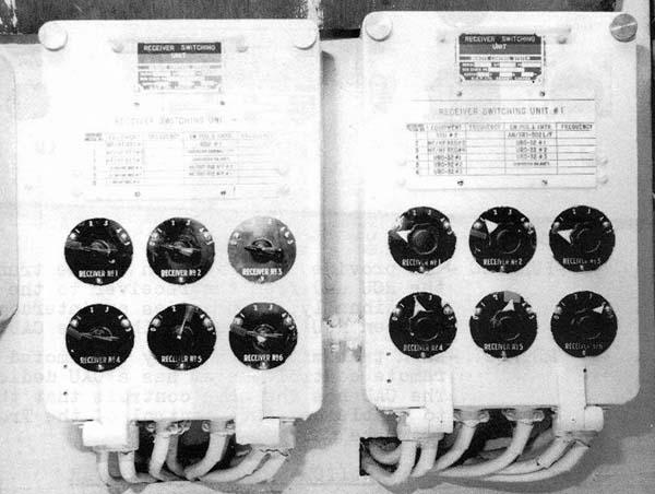
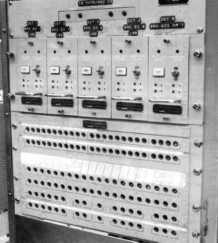
SB 5086/SRA-504
Switchboard patching Communications is where the audio and keylines
from transmitters, receivers and adapters enter the Receiver/ Transmitter
Control system and are allocated to various channel amplifier modules or
in some cases (such as RATT and Link 11) to equipment outside the receiver/transmitter
control system.
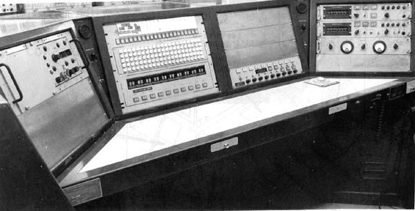
OJ 5002/SRA-504
Console consists of the following:
a) Up to 8 remote controls for AN/SRC 503/ WRC 501
b) Up to 6 TX/RX controls or AF/RF indicators for the AN/SRC 23
c) CCR monitor positions 1 and 2
d) Intercom System (AN/SIC503)
e) Control indicator (either C5205 or C5206)
f) Matrix switch assemblies (SA5042)
g) Control Power Supply (C5208)
h) Waste paper container
i) Jacks for headset/handset and CW keying
j) Automatic ship's telephone
k) Pull out shelf for typewriter.
l ) Two drawer filing cabinet
C5208/SRA-504
Control Power Supply contains main breaker, subsidiary switches, fuses
and a fault alarm for the PP 5200
MX 5129/SRA-504
Adapter provides facilities for the conversion of the HF transmitter
(AN/SRC 23) audio and keyline to the standards of the AN/SRA 504 system
MX 5130/SRA-504
Adapter provides for the conversion of VHF/ UHF transmitter and receiver
(AN/SRC 509, AN/VRC 49, AN/SRC 503, AN/WRC 501) audio and keyline to the
standards of the AN/ SRA 504 System
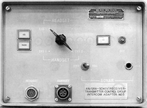
MX 5131/SRA-504
Adapter control intercom accepts the outputs of two CRS and the ships
intercom system and combines them into a binaural headset (Intercom on
left ear and selected CRS right ear)
J 5091/SRA 504
Jackbox provides facilities for connecting an operator in the CCR to
the AN/SRA 504 system (three monitor position).
PP 5200/SRA-504
Power Supply provides DC power to operate the matrix and all the indicator
lights in the control indicator. Control located in console but power supply
in separate rack -not shown
AM 5233/SRA-504
Amplifier, audio frequency provides audio amplification of the maximum
CRS output available from the handset/headset jacks to the level required
for the landing Safety Officer console positions. (not shown)