AN/ARC-552
 |
| ARC-552 general purpose AM transmitter/receiver designed for ship to
aircraft line of sight communications. It is similar to the ARC-27.(Photo
courtesy Canadian Navy)
NOTE: The control head is NOT an integral part of this transceiver. It has simply been placed on top of the case for this particular photo. Because of lack of contrast, the eye is easily fooled into believing the control head is integral to the radio. Frequency range: 225 to 400 MHz with independent Guard receiver for
243 MHZ.
BRIEF TECHNICAL DESCRIPTION The circuitry of the AN/ARC-552 Radio Set consists of a high-level, modulated transmitter; a tunable, double-conversion, superhetrodyne receiver; a single-channel guard receiver; frequency generating circuits and a power supply. Tuning is accomplished by an autopositioner which drives a mechanical linkage and accurately positions the tuning elements in the frequency generating and RF circuits as dictated by the control unit in use. Injection frequencies for both transmit and receive functions are obtained from the same crystal controlled oscillators. The guard receiver is a single frequency receiver which operates on a pre-determined frequency between 238 megacycles and 248 megacycles. The guard frequency normally assigned is 243 megacycles. The guard receiver is separate from the main receiver; however, both receivers use the same audio output stage. CONTROL CIRCUITS Radio Set Control Unit C-5062/ ARC-552. This unit provides full control
of the AN/ARC-552 without any additional control units. It is equipped
with four frequency selecting controls, a channel selector, a function
switch. a volume control and indicating lights. The channel selector switch
has 18 channel positions. plus guard and manual positions. Each of the
18 channels may be assigned to specific frequencies by setting up frequency
selector pins in the bottom of the unit. After the initial setting up is
complete, the channel selector may be switched to any channel and the auto
positioner in the Receiver-Transmitter will automatically tune the equipment
to the assigned frequency.
This article from the September 1957 issue of Flighglobal complements the above information. An order for airborne U.H.F. communications radios worth no less than
$8.3m has been placed by the R.C.A.F. with Collins Radio Company of Canada,
Ltd. The equipment involved is the
The ARC-552 and 52 offer a total of 1,750 channels in the the frequency band 225 MHz to 400 MHz. While all these are available to the pilot, nineteen of them are pre-set and can be selected for immediate use. An entirely separate guard channel is also available for emergency. ARC-52 and ARC-552 are completely interchangeable for installation purposes. The new Collins equipment offers considerable advantages over its widely used predecessor, the AN/ARC-27. It has 20 per cent fewer tubes; and its weight, at 51.5 lb, is 35% lower. The volume has also been reduced by 51 per cent. The ARC-552 is pressurized for operation at heights up to 70,000ft; printed circuitry and modular construction with standardized subassemblies are used; and all components are conservatively rated to increase their service life. |
AN/SRA501
 |
 |
|
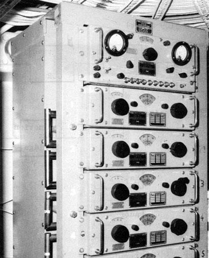
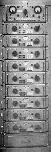
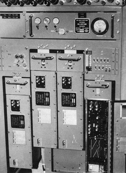
| AN/SRA501. Up to nine manually tuned CU-5044 couplers enable a maximum of nine transceivers to operate into one antenna in the 225 to 400 MHz band. Only four couplers are shown in the photo. A 1% frequency separation is required. At the top is one TS 5035 RF power test set. (Photo courtesy Canadian Navy) | The full system. (Photo courtesy Canadian Navy) |
The Antenna Coupler Group AN /SRA-501 is a VHF multicoupler used to provide electrical isolation between nine transmitters, nine receivers, nine transmitter-receiver groups or a combination of these operating simultaneously into a single broadband antenna.
SPECIFICATIONS
Frequency Range: 225 to 400 MHz
Impedance: 50 ohms
VSWR: Less than 1.3 to 1 over frequency range covered
Power Rating: 250 watt (100% AM)
Isolation between Channels: At 400 MHz +/- 3 megacycles - Greater
than 60. 5 db
At 225 MHz +/- 2 megacycles - Greater than 65.5 db
Insertion Loss at Resonance: Approx. 0.5 db additional loss
Physical: 74.5 in High by 26 in (30 in over junction cable) Wide
by 28.5 in Deep.
Weight: 811 lb.
Power Consumption : 117 volts nominal, 60 Hz, 1 phase
Manufacturer: Sinclair Radio Labratories
Antenna System: AS-101B/URC or similar.
Handbook: BRCN 4264
UNIT DESCRIPTION
1 Rack, Electrical Equipment MT-5068/SRA-501 Stock # 5985-21-041-2232
1 RF Power Test Set CU-5035/SRA-501
Stock #5985-21-041-2231
9 Antenna Coupler Channels CU-5044/SRA-501 Stock # 5985-21-041-2233
8 Junction Cables - 7/8" Rigid Coaxial
1 Junction Cable (Extra Long) - 7/8" Rigid Coaxial
2 Coaxial Adapters 'N'-7/8" EIA
The Test Set and the nine Coupler Channels are mounted in the rack by
means of chassis track slides. The Test Set is located at the top of the
rack and the nine coupler channels are stacked consecutively from one to
nine downward from the Test Set. A stowage drawer for spares is located
at the bottom of the rack.Type 'N' input and 7/8 inch EIA output connectors
are provided at the rear of each coupler channel. The outputs of each
coupler are interconnected by the rigid coaxial junction cables. All
controls and the metering panel of the Test Set are accessible from the
front of the equipment.
BRIEF TECHNICAL DESCRIPTION
Each antenna coupler consists of three silver-plated, cascade-connected, quarter-wavelength coaxial cavities. Transfer of energy is accomplished by fixed input and output loops in conjunction with ports or apertures between cavities. Tuning of the channel takes place when the telescoping centre conductors located in each cavity are increased or decreased in length. A system of spring loaded gears mechanically couples the centre conductors to a manual crank. The frequency to which the channel is tuned is indicated by a direct reading dial on the front panel. The nine coupler channels are connected in cascade, by means of nine coupling units, into a common coaxial terminal to which the antenna is connected. The RF Power Test Set provides indicators for tuning and metering the individual or combined outputs of the nine coupler channels. Nine switches on the Test Set, in conjunction with nine coaxial relays and nine low power VHF dummy loads, permit the associated transmitters to be pretuned during periods of radio silence.
AN/SRC503
 |
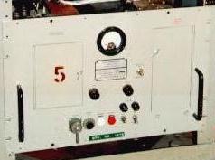
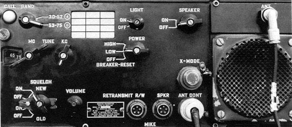
| AN/SRC-503. Frequency Range: 225 to 400 MHz. Modes: Voice, AM Wide Band Secure. Power Output: 10 to 100 watts variable. Some units were fitted with the Guard receiver module for 243 MHz. For remote control operation the C5215 unit ( not shown) needs to be fitted. (Photo courtesy Canadian Navy) |
AN/SRC-509 (SEALAND 66)
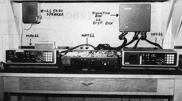 |
| AN/SRC-509 ( Sealand 66) VHF FM Voice Transceiver. (Photo
courtesy Canadian Navy)
Frequency Range - 156.025 to 158.5 MHz in transmit ; 156.3 to 163.0
MHz in receive.
Associated Units: SRC 66 (Standard control unit) provides remote facilities for selection of the channel, high/low power, and dual watch operation of any two channels. (Normally located on the bridge) MRC 66 (Master Control Unit) provides facilities for local operation or remote operation. When using the SRC 66 the MRC must be in position 1. When using through the ships remote system the MFC must be in Local or Position 1. MRT 66 (Transmitter /Receiver) contains main transmitter and receiver. AMPLIFIER- (Not shown). Audio amplifier for use when receiving
into the ship's remote system.
DIST. BOX provides a junction box or all cables. KEYLINE MATCHING UNIT (Not shown) enables the key line from AN/SRA 504 remote system to be adapted to the Sealand equipment. Used only on DDH 280 and AOR classes. Manufacturer: Redifon Telecommunications Ltd., London England.
|
AN/VRC49
 |
| RT 524/VRC 49 transceiver. 30 to 75.95 MHz;. FM voice; 35 watts (high) and 1 to 3 watts (low). The 280 class ships had two units and their antennas were fitted to the top of the hanger on both the port and starboard sides. (Photo courtesy Canadian Navy) |
 |
|
|
RT-5043(P)/WRC 501(V)
 |
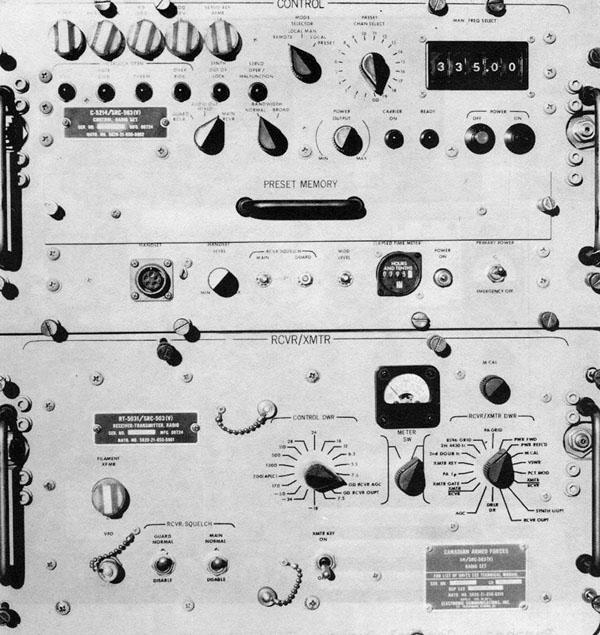
| Above: C5301/WRC-501(V) Control Indicator is used for remote
control operation. Vintage 1976 (Photo courtesy Canadian Navy)
Below: RT-5043/WRC-501 (225 to 400 MHz) general purpose transceiver.
|
AN/WSC-3
|
| Above: C9351A/WSC-3 (V) Control Indicator for remote control
operation
Below: AN/WSC-3 (225 to 400 MHz) general purpose transceiver.
|
OE 5012/VRC ANTENNA COUPLER GROUP
 |
| OE 5012 (V) /SRC VHF-UHF Antenna Coupler Group. Only a partial transmit
group is shown. This device enables the connection of up to eight VHF/UHF
transceivers to a single antenna. Tuning separation between channels
must be 1 MHz minimum. (Photo courtesy Canadian Navy)
Each group consists of :
Frequency Range 200 to 400 MHz.
|
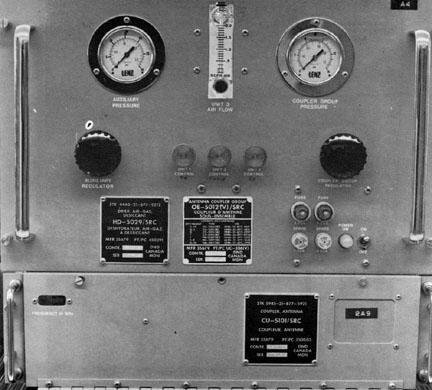 |
| Top: HD5029/SRC Air Dryer (part of OE 5012). This unit purifies the
ship's air for use in the OE 5012 couplers and the feed line to various
other antennas and for the satcom antenna as well.
Bottom: CU 5101/SRC Guard Receive Coupler (part of OE 5012). Its installed in the cabinet of the OE 5012 and is used to guard the 243 MHz UHF distress frequency. Tuneable from 238 to 248 MHz. (Photo courtesy Canadian Navy) |
SATCOM
 Satcom system cabinet. The entire system consists of the following components.
AS 28l5/SSR-l ANTENNA (4 fitted) - Stationary antenna for broadcast
reception.
(Photo courtesy Canadian Navy) |
|
|
|
|
|
|
 |
280 Class VHF/UHF System. This block diagram illustrates the interconnection of many of the devices featured above. Note the number of VHF and UHF transmitters which are feeding a single AS-5104 antenna through the couplers. If it wasn't for the couplers, imagine the nightmare of antennae which would have to be mounted on yardarms to support nine VHF/UHF radio circuits! (Diagram courtesy Canadian Navy) |
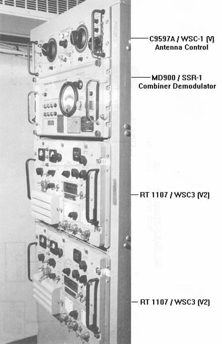
 |
280 Class Satellite Broadcast block diagram. Four AS2815 SSR-1 antennas feed the MD900 Combiner /Demodulator. It is believed this is satellite diversity reception scheme. From there, the signal is applied to the TD 1063A/SSRI demultiplexor which extracts the16 data channels. Following that, the data is patched to the crypto system, decoded and applied to the SB-5110 Black patch panel for further distribution. (Diagram courtesy Canadian Navy) |
 |
280 Class SATCOM (2 way). Two AS-3018 satcom antennas are used in pairs for receiving and transmitting. Connecting to this system, at the bottom of the diagram, are two KW-7 crypto units for the data and one KG-34 crypto box for the voice. The CV-3333 VOCODER converts voice from analog to digital and vice versa. (Diagram courtesy Canadian Navy) |
 |
280/AOR Class VHF/UHF RADIOTELETYPE. After
the RATT signal was converted into Baudot code, it was applied to the crypto
unit for decoding. The resultant plain text message was then handled by
the Message Handling System consisting of the AN/UYK-502 computer.
(Diagram courtesy Canadian Navy) |