a) From the Library Archives of Canada, Record 24, File # 7400-189/165
Parts 1 through 7.
b) From those who served at Churchill.
IRS means that this equipment was definitely used when Churchill was an Ionospheric Research Station. The archives file also reveals that in 1949, the station used two rhombic receive antennas and two transmit antennas. There were also 796 spare vacuum tubes in inventory along with an assortment of replacement components and various hand tools. The inventory recording was so thorough, it accounted for even machine screws and nuts. There were errors in the source material which have been corrected. If anyone can provide missing information, contact: jerry.proc@sympatico.ca
RADIO EQUIPMENT USED AT CHURCHILL
(Click on image to enlarge)
| EQUIPMENT | VINTAGE | USE | DESCRIPTION |
| Need photo | Late 1949 | IRS | Antenna Switch Model SA-136/G and 137/G. The base commander was instructed to replace the 20 position antenna switch Model SA-136/G with a 40 position switch Model SA-137/G. |
| Need photo | Oct. 1949 | IRS | Marconi Mk II P. F. equipment .Qty 1. Description unknown. Need info. |
| Need photo | Oct. 1949 | IRS | Type 249. Ionospheric Transmitter. Qty 1. Description unknown. Need info. |
| Need photo | Oct. 1949 | IRS | S.R.E. Qty 1 . Sound Reproducing Equipment S/N 456. Model unknown . Included are 7 speakers. Description unknown. Need info. |
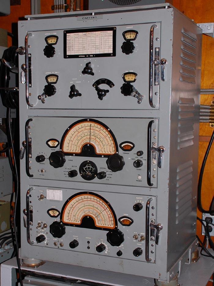 |
Oct. 1949 | IRS | CM11 . Canadian Marconi HF transmitter/receiver. Qty 1. Was slated for redeployment to DOT when a replacement transmitter arrived. Frequency range: 375 to 515 KHz and 1.5 to 13.5 MHz. Modes and power levels were: CW - 100 watts; MCW - 70 watts; AM - 30 watts. (Photo by Jerry Proc) |
 |
Oct. 1949 | IRS | CSR-5A Canadian Marconi HF Receiver By 1949, Qty 4 .(S/N 830, 868, 934 and 1057). Accompanied by qty 5, VP-3 power supplies and 5 speakers. Employed for WWV monitoring. All were slated for redeployment to DOT when replacement receivers arrive. By September 1950, the complement grew to 10 receivers. S/Ns 209, 245, 430, 440, 477, 657, 708, 729, 748,769. Used in Operations. There were still 10 receivers on strength as of Sept 1958. (Photo by Jerry Proc) |
 |
Sept. 1949 | IRS | National NRB-J receivers. (This is actually the Model RBJ). Qty 2. By September 1950, the quantity had grown to four units. Still four units on strength as of Sept 1958. (Photo courtesy Kurrajong Radio Museum, Australia) |
 |
Sept. 1949 | IRS | RCA AR-77 receiver Qty 1. Frequency range- 540 to 31000 KHz receiver. Produced by RCA Victor. Being used in Operations in Sept. 1950. Still in use as of Sept 1958/ (Photo by John Kaminsky) |
 |
Oct. 1949 | IRS | Sparton Model X1 receiver . Circa 1940's. 460 KHz to 30 MHz coverage. Depicted is serial number X1054. Manufactured in early 1940's (Photo by Jacques Hamel, VE2DJQ). |
 |
Sept. 1950 | RCA AR 8510 receiver. Qty 1. S/N 4770. Frequency range: 16 to 650 KHz. Used in Operations. Still in service as of Sept 1958. (Photo by Jerry Proc) | |
 |
Sept. 1950 | Sparton CNF-1 (s/n 91) HFDF: A CRT based
set having 2.7 mc to 25 mc coverage depending if it was the A, B or C variant.
(Photo
by Leblanc, DND. National Archives of Canada, photo # PA-142540)
Later, the CNF-1 was upgraded to a CNF-4..Only one CNF was ever issued to HMCS Chyrchil, |
|
 |
Sept. 1950 | RCA DR-89A Diversity Receiver. Qty 2. Consisting of three RCA CR-88 receivers. The DR-88 uses three AR-88 receivers while DR-89A uses three CR-88 receivers. Used in Operations. There were two DR89A diversity receivers on strength os of Sept 1958 (Image courtesy Canadian War Museum Library) | |
 |
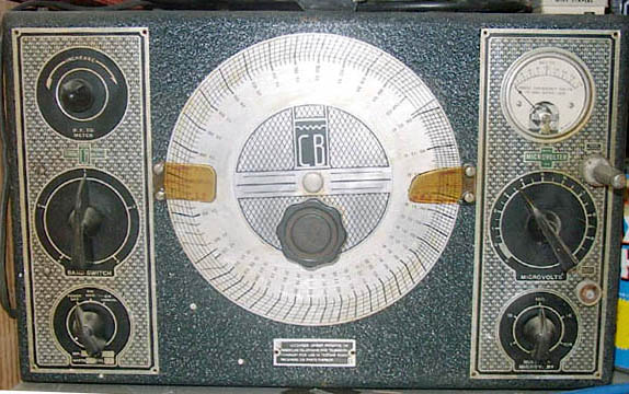
Sept. 1950 | CR-88 receiver by RCA . Qty 2. 535 KHz to 32 MHz. Used in Operations Two units on strength as of Sept 1958..(Photo courtesy www.oldradios.co.nz) | |
| Need photo | Sept. 1950 | Mecanitron 126F [2] .Qty 5. Description unknown. Need info. | |
| Need photo | Sept. 1950 | Mecanitron 126RC. Qty 5. Description unknown. Need info. | |
| Need photo | Sept. 1950 | Mecanitron Tape Pullers. Qty 10. Description unknown. Need info. | |
| Need photo | Sept. 1950 | Mecanitron Tone Keyer. TK1. Qty 2. Description unknown. Need info. | |
| Need photo | Sept. 1950 | Mecanitron Scanner Model SC22 with YY2 tape puller. Qty 1. Need info. | |
 |
Sept. 1950 | Northern Radio Frequency Shift Converter Model 107 S/N N15. Qty 1. (Photo by Jerry Proc) | |
| Need photo. | Sept. 1950 | Antenna Multicouplers with external power supply. Qty 8. Description unknown. Need info. | |
 |
Sept. 1950 | Model 19 Teleprinter. Qty 2. Circa 1942. 60 words per minute, 5 level Baudot coding. (Photo by Jerry Proc) | |
 |
Sept. 1950 | Model 14 TD (Transmitter-Distributor) Tape reader for Baudot tape. Qty 3 (Photo by Jerry Proc) | |
 |
Sept. 1950 | Model 15 KSR Teleprinters. Qty 2. 45.5
baud, 60 wpm. Manufactured from 1930 to 1954.
(Photo by Jerry Proc) |
|
| -- | Sept. 1950 | Model 15 RO Teleprinter. Qty 2. Receive Only. Same as KSR above but without keyboard. | |
| Need photo | 1950-1956 | TH-58 transmitter. 1 kw power output. It was located in a shed-like structure not far from the base hospital in the camp at Fort Churchill and sometimes referred to as Old Camp.Used for communications with Frobisher Bay and Aklavik | |
 |
March 1951 | Hammarlund SP-600-JX Receiver: Qty 8. 540 kHz to 54 MHz. Replacement for CSR-5A's. Six were installed in the Ops Bldg and two in the D/F building. (Image courtesy Kurrarjong Radio Museum) | |
| Need photo | April 1951 | Motorola Porta-Phone Unit. Description unknown. Need info. | |
 |
1953 | The CCM Coding Machine was in use at Churchill in 1953. Shown with cover off. This cryptosystem was replaced with the ECM Mk II starting in 1954. (National Cryptologic Museum Foundation photo) | |
 |
1954 | ECM Mk II replaced Typex in 1954. Used for the encipherment of classified material. (Photo by Richard Myrick) | |
 |
1950's | McElroy Model RAPC ink tape recorder. This was a real workhorse at Churchill and was used to copy CW which was beyond the capability of the receiving operator. This recorder could copy signals up to 1,000 wpm. An ink tape operator could always be identified by the thin line of ink spatter across his gun shirt. (Image courtesy RCN) | |
| Need photo. | From actual field tests at Coverdale , the Boehme was found to be a better ink strip recorder that the Mecanitron units that were used in Churchil.. A replacement request was subsequently placed with Ottawa in March 1951, | ||
 |
1950's | Pierce Model 556 wire recorder. Both Pierce and Webster wire recorder types were used at Churchill. Both types had very poor sound fidelity and mechanical deficiencies. Pierce was especially problematic when doing a 'rewind' or 'fast forward' which resulted of heaps of tangled wire on the floor. (Photo courtesy Northern Illinois University) | |
 |
1950's | Webster Model 80 wire recorder. (Photo courtesy Northern Illinois University) | |
 |
1950/60's | Ampex 601 dual track tape recorder. (Image courtesy of RCN) | |
 |
1953 | XFK Keyer. A document dated Nov. 1953 is requesting crystals for an XFK keyer which feeds the TH-58 transmitter. Crystals are required for the following frequencies: 4570, 6707.5, 9022.5, 13412.5 and 18087.5 KHz .In addition to the above frequencirs the fpllpwing crystals were requisitioned for The keyer cost $1050 and the crystals were $25 each in that time. (Photo by Jerry Proc) | |
 |
1956 | By 1956, there was a requirement to establish reliable point to point circuits from Churchill to Aklavik, and Frobisher Bay. so a Westinghouse MW transmitter was collocated at the Joint Services Transmitting Building, not HMCS Churchill itself. Depicted here is an MW installation at radio station WNU Slidell, Louisiana. Frequency range: 2 to 30 MHz; Power Output: 3,000 watts. Modes: A1 and F1; Frequency control: 3 crystal controlled positions per RF unit. All four RF units can be keyed simultaneously or independently. Instruction Manual: CF-1933. Known operating frequencies for SUPRAD service were: 4570, 6800, 6956, 9216 and 13412.5 KHz. The MW (cost $35,000) was to be the replacement for the TH-58. (Photo courtesy WNU6) | |
 |
Returned to Montreal stores, April 1959 | FM12 MF/DF set. Made by Marconi UK in 1942, this is a Tuned Radio Frequency, direction finding receiver with a frequency range of 42 to 1060 KHz and requires 220 VAC input power. [1] (Photo by Jerry Proc) | |
 |
Returned to Montreal stores, April 1959 | IRS (?) | FM12 fixed-frame loop antenna. [1] (Photo by Jerry Proc) |
 |
1960's | AN/GRD-501 . In 1959, approval is given to start the construction of a GRD-501 site at a cost of approximately $88,000. Rowland Fell, who served at Churchill from 1965 to 1967, confirms the use of the GRD-501 direction finding receiver. It was only used for special assignments in that time period. It was the replacement for the station's FM-12 MF/DF receiver. (Photo courtesy Canadian Navy) | |
 |
1950s - 1960s. | Front and sude views of the Rockex cipher machine. Click on image to enlarge. (Photo by Jerry Ptoc ) | |
| No photo available. | 1940s (?) , Exact model
unknown. |
The Marconi Mk II P.F. equipment is a ta generic name for a type of
Direction Finding (HF/DF) radio receiver developed by Marconi's Wireless
Telegraph Company Ltd during or shortly before World War II.."P'F"is an
abbreviation for Position Finding or Position Fixing, a British term commonly
used in wartime. Mark II is the second version of the equipment..
Another source says "The Marconi Mk II P.F. system wasn't a single device, but a position-finding network built around direction-finding technology, with the P.F. portion referring specifically to the centralized plotting and location-finding function" |
|
| Need photo | 1958 | Antenna Multicouplers. - Quantity 9 in use as of Sept 1958 | |
| Need photo | SRE 456 entertainment receiver. |