 |
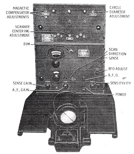
| DAU set showing locations of controls. It consists of three units. They are: the Receiver Unit, Rectifier Power Unit (or scanner unit) and the Automatic Bearing Indicator Unit. (Photo courtesy RCN) |
FUNCTION OF CONTROLS
RECTIFIER POWER UNIT (or Scanner Unit)
a) Magnetic compensator - Two screwdriver controls are used to
adjust the CRT trace. Whenever the two sides of the pattern exactly at
the centre, the following should be made.
(1) Turn the sensitivity control full up. The resulting set noise should
collapse the trace to a dot or a very small circle.
(2) On "Direction", adjust the top screwdriver control for the smallest
circle diameter, and the bottom screwdriver control for a dot.
(3) If necessary, go back and forth between the two controls until
the best spot is achieved.
b) Circle Diameter - This control adjusts the diameter of the CRT trace. It should be adjusted so that the trace lies just inside the azimuth ring around the tube.
c) Scanner Centering - On "Direction", a signal .should first be tuned exactly to resonance (zero beat) by obtaining the narrowest propeller pattern. Switch to "Scan" and adjust the scanner centering control so that the above tuned signal appears at the top of the scan pattern. This control should be adjusted every few hours.
AUTOMATIC BEARING INDICATOR UNIT
The indicator unit consists of the CRT, the motor, and the goniometer. Five controls are present on the indicator unit. They are:
a. Horizontal positioning.
b. Vertical positioning.
c. Focus.
d. Intensity.
e. Azimuth lamp - located on the right side of the tube housing, adjusts
the brightness of the azimuth scale lamp.
RECEIVER UNIT
1. Contains a conventional band-change switch, tuning dial, power switch, BFO, and BFO adjust.
2. Scan-Direction Sense Switch - This switch determines the type
of display desired on the CRT. This is explained in greater detail below.
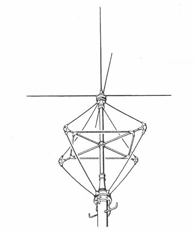 |
| DAU antenna, was sometimes referred to as a birdcage antenna. The short whip atop the loops is the sense antenna (Graphic courtesy RCN). |
The Scan-Direction-Sense switch determines the type of display desired
on the CRT. These are illustrated below.
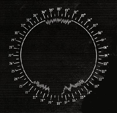 |
| Scan Position (no signal) - In this position, the CRT display shows all signals within a 150 kHz. passband (75 kHz. on either side of the frequency to which the. receiver is tuned). This is a special feature of the DAU which allows the operator to visually monitor a band of frequencies 150 kHz wide. The operator will only hear those stations to which the set is tuned to. In the scan position, the DAU is only a wide band receiver not a DF set. |
 |
| Scan Position (signal) - Signals which are lower in frequency than the one tuned in will appear as triangular indentations on the right hand side of the trace. Signals higher in frequency will appear on the left hand side of the trace. |
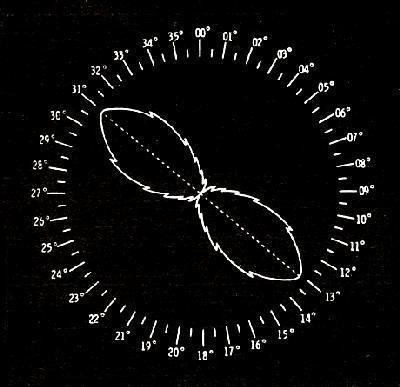 |
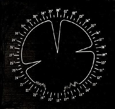
| Direction Position - In this position, the "propeller", or directional pattern of the signal being received by the antennae is obtained. The propellor points to the bearing of the signal and its reciprocal. |
 |
| Sense Position - With the switch now in the Sense position and the Sensitivity Control and Sense Gain Control adjusted properly, the wing of the propeller will fold back this, forming a heart-shaped pattern. The tip of the heart indicates the bearing of the signal. However, if the Sense Gain is turned fully down, the propeller pattern will merely shift 90 degrees. In actual operation, a perfect heart-shaped pattern will seldom be obtained. |
|
|
HOW TO TAKE A BEARING
[From the manual]
It will be assumed that the assignment of the operator is to monitor a frequency range of 150 kHz. wide, and to obtain a bearing on any station located in that range.
1. Turn on the set by throwing the Master, Beam, and Motor Switches
on the Rectifier Power Unit.
2. Turn on the receiver by throwing the Receiver Power Switch.
3. Switch to "SCAN".
4. Adjust the Intensity, and Focus Controls for a sharp, clear trace,
not too bright. Adjust the two Positioning Controls to centre the trace.
5. Adjust the Circle Diameter and Magnetic Compensator Controls.
6. Adjust the "Scanner Centering".
7. Tune the receiver to the centre of the band to be monitored.
8. Adjust the Sensitivity Control until noise first appears on the
trace. Advance the Sense Gain Control until the noise increases slightly.
9. When a "BLIP" (a signal indication) appears on the scan trace, tune
the signal to resonance by moving it to the top of the scan trace. This
is done with the Receiver Tuning Dial.
10. Switch to "DIRECTION".
11. Tune the receiver for the narrowest propeller pattern.
12. Adjust the Sensitivity Control to close the centre of the propeller
pattern.
13. Move the Cursor over the tips of the propeller.
14. Switch to SENSE".
15. Advance the Sense Gain until the ears of the pattern bend together.
16. Read the Azimuth Scale at the end of the Cursor away from the sense
pattern. This is the correct bearing, unless station calibration has shown
sense to be reversed on this frequency.
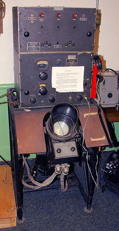 |
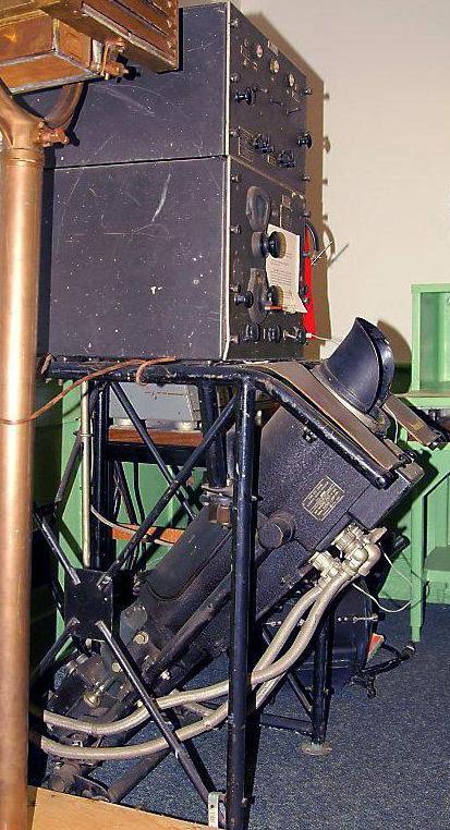
| Above and below: The DAU set held by the MARCOM Museum in Halifax. (Photos by Sandy McClearn) |
 |
TEST OSCILLATOR
James Hanlon provides a description for a Type CFT-52300 Radio Transmitter which was used to calibrate the DAU in a fixed installation.
Supply: Internal Battery.
Manufactured for Navy Department - Bureau of Ships by contractor Federal
Telephone & Radio Corp., Newark, New Jersey, Contract NXsr -41007,
Accepted by Navy Jan 1945.
 |
|
|
"It comes in a black box about 7"x7"x9". There is a large insulator
on top with what appears to be a screw-in mount for a whip antenna.
The front panel has a National NPW (HRO type) dial, a four position band
switch, and three switches for HI/LO, On/Off, and ICW/CW. The labels
on the four switches are engraved bakelite strips bolted onto the
panel. On the side of the box is a calibration chart specific to
Instrument No. 393 and dated 12-20-44. It shows that band 1 covers
1.5 to 3.25 and I presume that is Mc, band 2 covers 3.5 to
6.5, band 3 covers 6.75 to 14,5, and band 4 covers 15.0 to 30.0. Inside
there is a large, two section variable capacitor, two tubes, a 1R5 and
a 3B7, a four position, three gang bandswitch with four sets of coils on
it, two sets of battery clips that look like they would hold D-cells, a
mounting bracket that was probably intended for a B+ battery plus wires
with battery clips on them nearby, and a variety of small parts under the
chassis. There are two clips on the tuning assembly that engage studs
on the bottom of the antenna mount and on the inside, bottom of the box
when the chassis is slid into the box".
Contributors and References:
1) Royal Canadian Navy: BRCN 3040
2) James Hanlon <knjhanlon(at)msn.com>
3) Sandy McClearn <smcclearn(at)ns.sympatico.ca