By 1985, the Oberons had their communications mast modernized with
the fitting of the AN/BRA-34(V) antenna group. No information is available
to show which variant was fitted in Canada's boats. It is assumed
that the Oberons were retired with the BRA-34 antenna group.
The AN/BRA-34(V), AN/BRA-34A(V), AN/BRA-34B(V) are multifunction antenna
groups that provide signals for the following radio bands or services:
VLF/LF, MF/ HF, UHF line of sight (LOS), navigation (NAVSAT), UHF
satellite communications (SATCOM), IFF (Identification Friend Foe) and
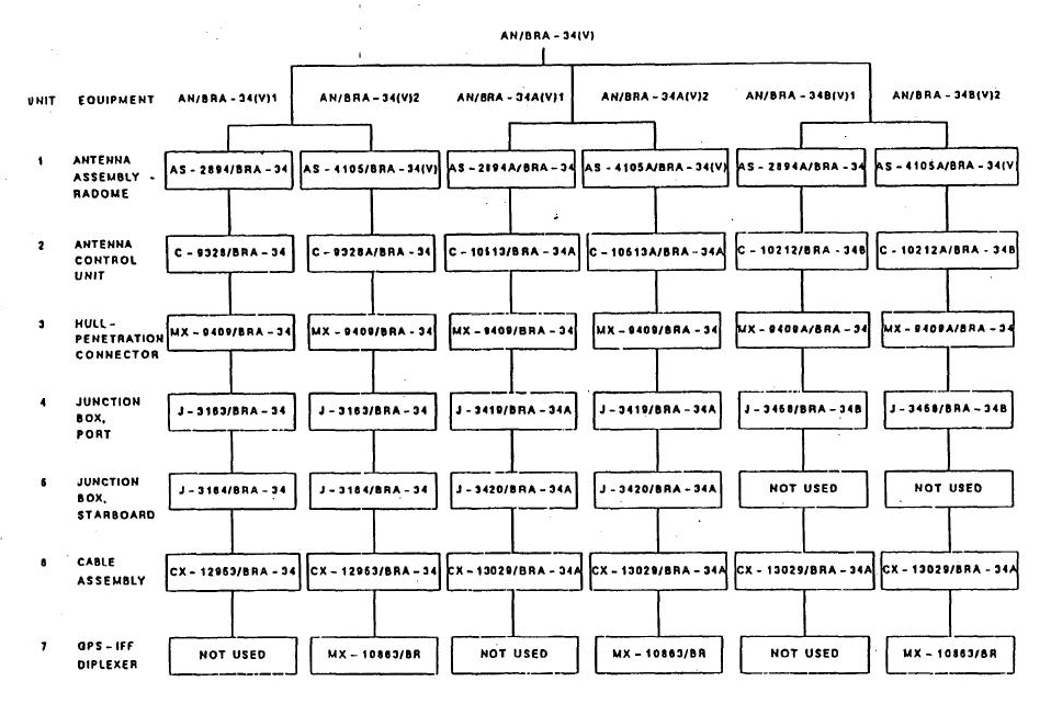
GPS (Global Positioning System). There are six configurations for the AN/BRA-34
group. They are as follows: AN/BRA-34(V)1, AN/BRA-34A(V)1, AN/BRA-34B(V)1,
AN/BRA-34(V)2, AN/BRA-34A(V)2 and AN/BRA-34B(V)2.
TPUB.com has the best documentation of all so extracts from their documents
are posted here.
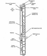
DESCRIPTION OF INDIVIDUAL ANTENNA COMPONENTS (TOP DOWN)
GPS ANTENNA (Unit 1A6E2). The GPS antenna is used for the reception
of GPS satellite signals. Frequency range is 1227 +/- 10 MHz
and 1575 +/- 10 MHz.
IFF ANTENNA (Unit 1A6E1). Frequency range 950 MHz to 1150 MHz
at a power level of up to 1 kw with a 10% duty cycle. A diplexer separates
or combines the IFF and GPS signals.
DEPTH TRANSDUCER (Unit 1A6) - It produces a voltage which is
proportional to the depth of the antenna below the surface of the sea.
The transducer is capable of withstanding a pressure of 1,000 psi.
VLF ANTENNA (Unit 1A7). The VLF loop antenna system provides
radio reception in the frequency range 10 kHz to 170 kHz. It operates in
conjunction with coupler CU-1441( )/BRR or CU-2364 /BRR. Another web document
quotes the frequency range as 5 to 150 KHz ( it depends on the variant).
The antenna uses two antennas whose reception patterns are figure eight's
and displaced by 90 degrees.
UHF DIPOLE ANTENNA (Unit 1A2) . This is a vertical dipole antenna
intended for UHF LOS transmission and reception, NAVSAT reception, and
UHF SATCOM low-angle transmission and reception. Frequency range is 225
to 400 MHz at a power level of 100 watts. Another web documents quotes
the frequency range as 240 to 315 MHz. This is probably dependent on the
variant of the antenna.
UHF HELIX ANTENNA (Unit 1A3). The UHF helix antenna is a quadrafilar
helix for the reception and transmission of SATCOM signals in an
overhead (high-angle) mode. The UHF helix antenna is compatible with a
UHF SATCOM transceiver operating in a simplex mode. Its frequency range
is is 240 to 320 MHz.
Tim Tyler adds to this . "The 240-315 MHz frequemcy range is the common
UHF SATCOM spectrum within the 225-400 MHz military band. US and NATO UHF
satellite transponders usually transmit in the 240-270 MHz spectrum, with
uplinks to the satellites operating in the 280-320 MHz spectrum. It sounds
like this antenna would primarily have been for surface to air and surface
to surface, with secondary UHF SATCOM capability, while the 1A3 antenna
was the primary UHF SATCOM one".
UHF SWITCH DECK (Unit 1A8). The UHF switch deck separates or
combines UHF and IFF signals or amplifies and filters VHF and UHF received
signals and provides relay selection of the UHF dipole antenna or UHF helix
antenna.
MF/HF ANTENNA (Unit 1A1). The MF/HF section consists of a helical
conductor wound within a pregrooved plastic form on which a metallic capacitive
top hat is mounted. Inside the helix and top hat, there is a shorting device
which consists of a metallic shorting tube with shorting brushes
at each end to complete the circuit between the helix and the top hat.
Frequency range is 2 to 30 MHz with a power rating of 1 kw. Impedance is
50 ohms
MODE SWITCH (Unit lA5). The mode switch provides
the capability to disconnect all antennas except the MF and HF antenna
for improved MF/HF transmission performance.
DUPLEX FILTER (Unit lA4). The duplex filter combines or separates
the MF and HF frequency bands and the UHF and IFF-GPS frequency bands.