VISUAL SIGNALLING in the RCN
LIGHT SIGNALLING
DIRECTIONAL AND NON-DIRECTIONAL LIGHT SIGNALLING
Flashing light signalling includes the use of searchlights,
yardarm blinkers and signal lanterns employing Morse code, special characters
and procedure. Directional flashing light is the term applied to the transmission
of signals by a narrow beam of light. Non-directional flashing light is
the term applied to the transmission of signals in all directions.
Don Wagner (USN, Ret'd) provides this introduction to Light Signalling.
"On RCN or RN naval vessels, the directional signal projector was
either a 10-inch Signal Projector or a 20-inch Signal Projector. In the
U.S. Navy, they also came in two sizes. The 12-inch signal/search light
used an incandescent bulb which could also be trained and elevated. There
were also 24-inch carbon arc signal/search lights. Both of these lights
were equipped with a handle on each side of the barrel (for left or right
handed operators to send visual (light) Morse code. The 12-inch range was
normally limited to about 14 miles or the horizon. The 24-inch carbon arc
was much more brilliant and the signals (at night) could be bounced off
the cloud cover and around the curvature of the earth. It has been told
in visual communicators circles that a Morse signal sent by light has been
confirmed (by radar) to have been sent up to a distance of two ships 80
miles apart!"
FLASHING LIGHTS
Non-Directional light signaling was accomplish by means of yardarm
blinkers. The blinkers were operated by telegraph keys fitted on a
ship's flag or signal deck. Some vessels also carried infrared blinkers.
During WWII, RCN ships were fitted with "fighting lights".
One source mades reference to the fact that fighting lights were used to
send emergency messages on a broadcast basis to a group of vessels
immediately preceding or during action. This use of coded visual communication
maintained security and could be construed as a form of visual IFF.
With directional light, the receiver would send a short flash on receipt
of each word. With non-directional signalling this was not possible. Obviously
the sender could not watch all the ships at once to see if they received
the word just sent. It was assumed that the entire message was received
otherwise any (receiving) signalman could request a repetition. During
routine operations, there were night exercises in which the yardarm or
masthead lights were used to send Morse flashing exercises to the ships
in company.
In the USN, infrared signalling was known in visual communications circles
as "Nancy Hanks". (Nancy Hanks was the maiden name of President Abraham
Lincoln's mother). An infrared viewer was necessary to view infrared transmissions.
In the USN, a Nancy viewer scope was also used to check for "light leaks"
during periods of darken ship. Very often it picked up the glow of light
from a "leaking" scuttle or someone having a smoke on the weather decks.
Infrared viewing scopes were quite amazing in that you could even turn
them on a dim star on a clear night and see that star quite clearly! In
the RCN, these lights were referred to as "Nancy".
Don Ross, a former Visual Signaller in the RCN comments on Nancy.
"When an infrared signal was about to sent, the radio code words were Nancy
Hanks. This was sent a few minutes in advance so the signalmen
could get the infrared reading device out of storage and be ready to read
the Morse code. We used it in training quite a few times, but the only
time I ever used it for real signalling was on a trip into the Baltic Sea.
We were being shadowed by a squadron of Russian (destroyer like) ships.
St. Laurent's Captain (Senior Officer) used infrared to signal course and
speed changes".
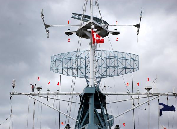 |
Signalling lights aboard HMCS HAIDA. 1- Truck lights for aircraft
warning and anti-submarine action. 2 - Masthead Flashing Lanterns.
3
- Yardarm Flashing Lanterns. 4 - Fighting Lights.
5 - Infrared lights. (Photo by Jerry Proc) |
 |
| This is a partial schematic diagram of the flashing light system. Both
port and starboard light sets ( ie fighting, masthead and yardarm) were
connected in parallel and keyed as a group except for the infrared lamps
which were keyed with separate Morse keys. The NUC lights are described
elsewhere in this document. (Image courtesy RCN) |
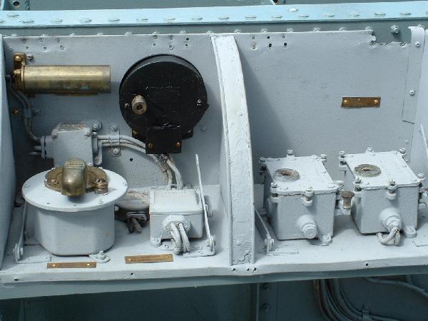 |
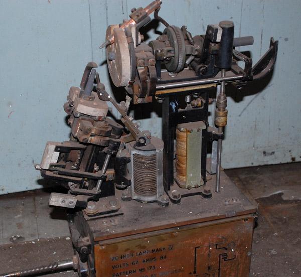
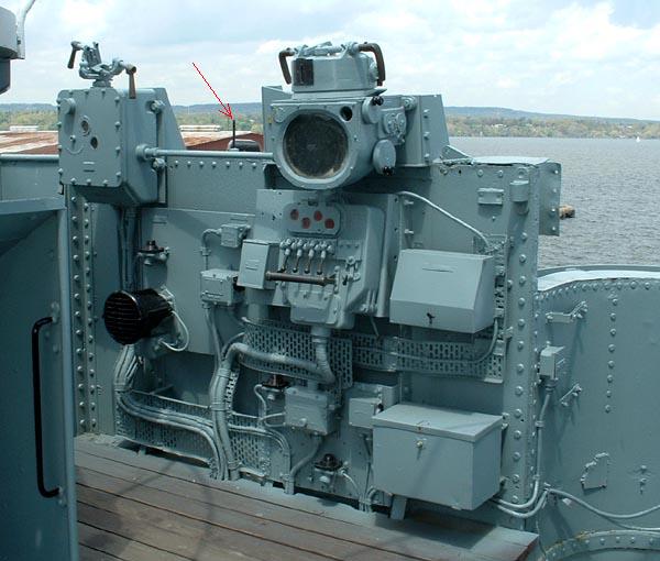
| In 2007 this flashing light control station aboard HMCS
HAIDA was restored after being under a metal cover for several decades.
In addition, three other similiar stations could also control the flashing
lights. One identical pair was on either side of the bridge and slightly
aft. The other pair of stations were on the port and starboard sides of
the flag deck. Normally a curved, hinged metal cover would protect the
keys from the elements. A typical signalling speed for flashing lights
would be around 13 wpm. (Photo by Jerry Proc) |
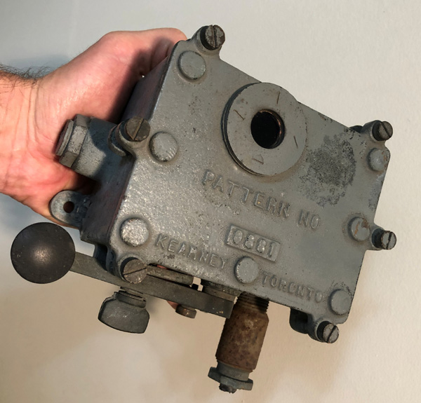 |
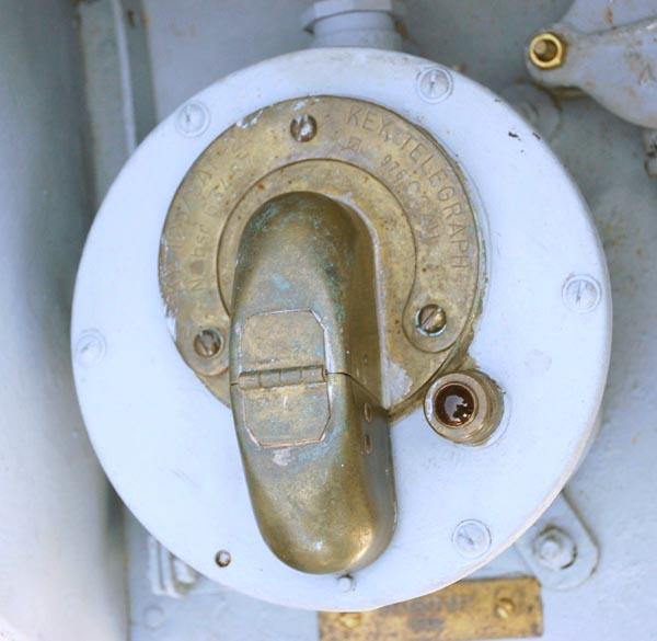
| A closer view of the yadarm light signalling key indicates pattern
0881 and was made by Kearney in Toronto. (Photo by Roma
Kuzhlev) |
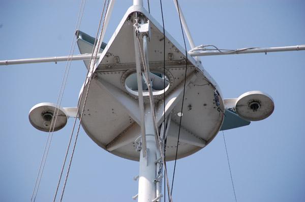 |
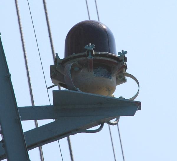
| Close-up of the flashing masthead lights attached to the
293 platform. The truck lights atop the shade cannot be seen from this
angle. (Photo by Jerry Proc) |
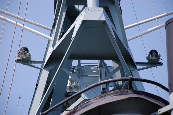 |
| Two infrared lights are fitted on each side of the lattice mast just
below the yardarm. (Photo by Jerry Proc) |
 |
| Close-up of an infrared lamp. Keith Kennedy also confirms
that infrared signalling was referred to as "Nancy" in the RCN. Sometimes
a reddish coloured infrared filter would be placed over the 10 inch signal
projector for infrared signalling but it resulted in a reduction in the
size of the beam. Infrared signalling was sometimes referred to as "dark
light" signalling. (Photo by Jerry Proc) |
 |
| A close-up of the infrared light control key. The key is shown with
its protective cover in the closed position. (Photo by Jerry Proc) |
SIGNAL PROJECTORS (SP's)
Most ships used 10 inch signal projectors but on smaller vessels,
hand-held Aldis lamps were used. Larger ships like destroyers also had
two 20" SP's on mountings either side of the bridge but at a slightly lower
level. SP's were used to communicate with other ships in Morse code and
were also known as Signalling Lanterns in the RCN.
10 INCH SIGNAL PROJECTOR
The 10" signal projector operates with a light beam divergence of six
degrees and 1 million candlepower output. In bright sunlight, a range of
10 miles can be expected. For night signalling the projector's light output
can be attenuated by the use of filters which either lessen the brilliancy
or convert the light to infra-red. This projector is still in use by the
Canadian Navy in 2007 and is carried on Iroquois Class, Kingston
class and a couple of Halifax class frigates but not HMCS Toronto.
With directional signalling, the operator sends at the speed of
the slowest reader. There is an acknowledgment flash from the reader after
every word. Repetition of words is quite common. The NATO standard
sending speed remains at 8 WPM.
 |
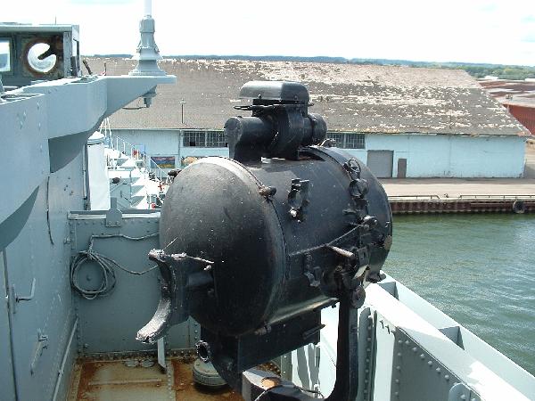
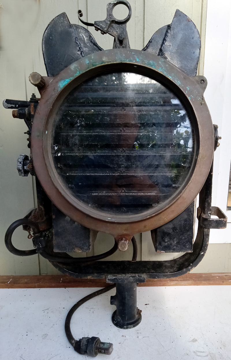
| This 10 inch signal projector on HMCS HAIDA's starboard side uses a
1000 watt filament-type lamp. It does not use a blower motor to exhaust
hot air. (Photo by Jerry Proc)
Nameplate data: Pattern 3860A; Serial 5676; Year: 1944; Made
by: General Electric, Toronto. It is not known if this particular projector
was original to the ship since there was little chance that Vickers-Armstrong
(HAIDA's builder) would use an overseas subcontractor during wartime. A
1944 date might suggest that the projector was replaced during a 1944 Canadian
refit or even later. |
 |
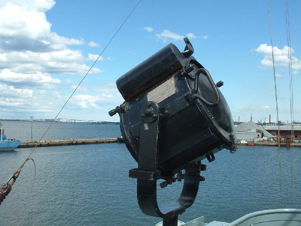
| Radio collector Richard Dillman is demonstrating a signal projector
aboard the S.S. Lane Victory. The size of the projector is believed to
be around 10 inches. (Photo via Richard Dillman) |
 |
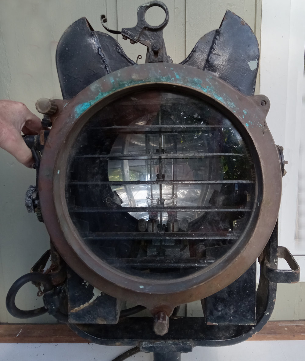
| Front view of a 10 inch signal projector. The
shutters are closed.
|
 |
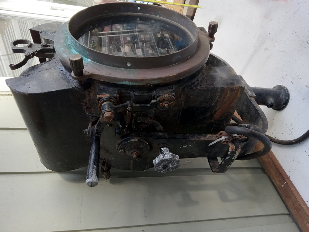
| With shutters open. |
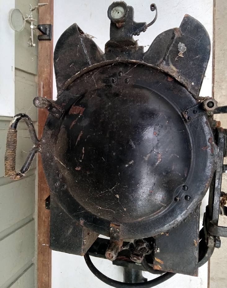 |
| Rear view |
 |
| Shutter handle detail. It's about 2 inches
in diameter. Bottom is at the right side. |
 |
| 1000 watt signal projector bulb. It's about
2.5 inches in diameter. |
 |
| Nameplate data. |
| All photos in this table by Simon Hall, VE7LBW |
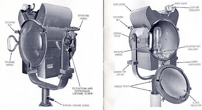 |
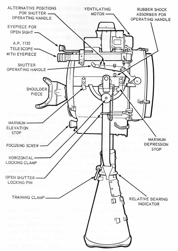
| Principal parts of a 10 inch signal projector. (Images
courtesy RCN) |
12 INCH SIGNAL PROJECTOR
The 12 inch signal projector, the same type as used by the United States
Navy, was introduced into the Canadian Navy fleet in approximately 1981.
Confirmation has been received that HMCS ALGONQUIN 283 had them by
January 1982. In 2007, the Canadian Navy fleet has approximately
a 50/50 mixture of 10 and 12 inch signal projectors.
The primary signal projector on Halifax and Iroquois classes is the
12 size.
20 INCH SIGNAL PROJECTOR
These projectors used a carbon arc light source. Each pair of
carbon rods lasts approximately 50 minutes. When used as a searchlight,
the lamp is focused so the beam is narrow, having a divergence of 2.6 degrees
and a minimum brilliance of 45 million candlepower.
When used as a signalling projector, the beam's divergence is increased
to 4.5 degrees thus giving a brilliance level in the order of 10 million
candlepower. A broader beam was more desirable for directional signalling
because it shows up on the horizon as a "splash" of light which is much
easier to see than the pinpoint of light characteristic of a searchlight
beam.
Banging one's hand on the shutter handle would not permit faster signalling.
The projector had be operated with light pressure of the fingers.
Special attention had be paid to the spacing of the dots and dashes to
ensure that the Morse code was readable. While signalling, one eye had
to be constantly in the sight so as to compensate for ship's own motion
and maintain a visual lock on the other ship.
Twenty inch signal projectors used by the USN used carbon rods about
12" to 15" long and had a diameter about the size of a pencil.
The use of the 20 inch signal projector was phased out by the Canadian
Navy around 1985. It is believed that HMCS Athabaskan 282 was the last
ship to use one.
 |
 |
 |
| Training aid with projector shutters
closed. |
Training aid with projector shutters
open.. |
Morse code reference chart, |
| This training aid was issued by the
RCN Director of Naval Education Training Aids. Click on any image to enlarge.
(Provided
by Ted Orlowski) |
 |
| On a Canadian Patrol Frigate, there is a signalling projector in each
of the bridge wings. Click on image to enlarge. (Photo by Darren Scannell) |
SEARCH LIGHTS
 |
| Shown, is a remotely operated ,2.5kw Xenon searchlight
on the bridge roof of a Canadian Patrol Frigate. Xenon search
lights are now used for (night) Man Overboard situations and also can be
used to illuminate a vessel being hailed. These Xenon lights were not available
in the 1960's. Click on image to enlarge. (Photo by Darren Scannell) |
12 INCH SEARCHLIGHT/SIGNALLING LANTERN
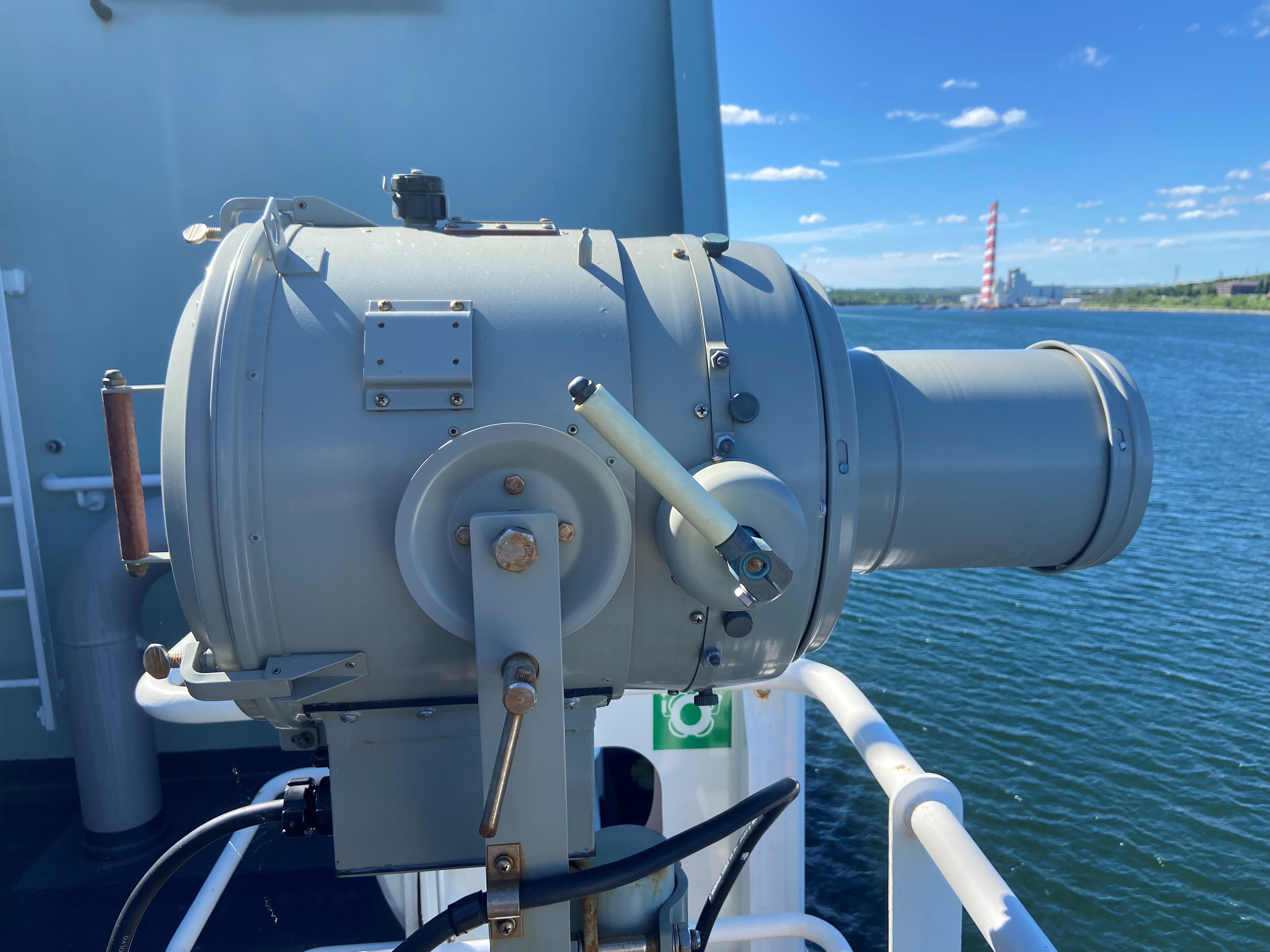 |
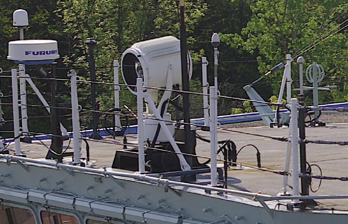
| The 12 inch signalling/searchlight is now being fitted to the Harry
Dewolf class ships. It is part number 95633NM (NATO # 6230-00-144-3442)
and made by Carlile & Finch of Ohio. The candlepower output is
not known at this time. Some of today's signalling projectors use LEDs
to generate light. Click on image to enlarge. (Photo provided
by Neil Bell). |
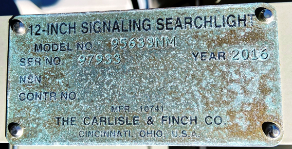 |
| Nameplate for12 inch signalling/searchlight. |
ALDIS SIGNALLING LANTERN
The RN first started using Aldis lanterns in the 1800's and the
rest of the navies adapted this form of flashing light using Morse
code. Royal Navy, RCN and USN versions of the Aldis were slightly different
whereby the USN models used a shutter to key the light beam while those
in the RCN and RN used a tilting mirror.
Those used in the RCN were hand-held projectors about 4 inches
in diameter, which had a pistol grip and a trigger to control the light.
Aldis lamps used either 12 volt or 36 volt bulbs to send messages in Morse
code. When using the ship's low power mains in DC fitted ships and when
using a portable battery, 12 volt lamps were used. The 36 volt bulbs were
used in AC fitted ships. Along the top, there was a sight which was used
to aim the lantern. The lantern was usually rested on the crook of
one elbow, held shoulder high while the other two triggers were operated
by the opposite hand. When using portable wet cell battery, the Signalman
had to ensure it was kept charged when not in use.
The pistol grip is fitted with two triggers. The lower trigger turns
on the lamp and must remain depressed for the duration of the message while
the upper trigger tilts the mirror. When the lantern is accurately trained
on the receiving station and even if the lamp is on, nothing will be seen
until the beam is raised by pressing the upper trigger. Releasing the upper
trigger drops the beam thus producing breaks between the dots and dashes
of the Morse code characters. During darkness, colored filters could
be attached to the lantern to reduce the lamp's brilliance.
The 5 inch Aldis lantern combines the features of the 4 inch Aldis lantern
and the Intermediate Lanterns. It uses the same power supply but produces
150,000 candlepower. Coloured shades can be secured to the front glass
to reduce the brilliancy for night signalling. HMCS HAIDA's electrical
drawing shows places for two 6 inch Aldis lanterns both running at 22 VDC,
however the Signalman Trade Group 1 Manual does not mention anything about
6 inch Aldis lanterns.
Don Wagner details USN usage of the Aldis. "In the USN, the Aldis lamp
had a 6 inch diameter barrel with a pistol grip and a "trigger" to operate
the lamp shutters. It was used by submarines on the surface and maritime
Navy patrol aircraft to communicate with destroyers engaged in depth charging
enemy subs. The lamp could be operated by plugging it into the ships power
mains or into a portable battery pack. The Aldis was also used in small
craft."
The Royal Navy phased out the use of Aldis lamps in 1997, although by
that time they were largely ceremonial. Other modern forces have followed
suit as technological advances in digital communications have made the
device obsolete. HMCS Toronto still carries five Aldis lamps on the bridge
for backup purposes.
 |
| Above and below: 4 inch Aldis lantern, pattern S5110E. Made by Sutton-Horsley
Co. Ltd, of Toronto Ontario. This one was last used on HMCS Labrador. Since
there was no battery compartment in the carrying case and the lamp has
a long power cord, it is believed it was powered from the ship's low voltage
power mains. Five inch Aldis lamps produce 150,000 candlepower. (Photo
by Jerry Proc) |
 |
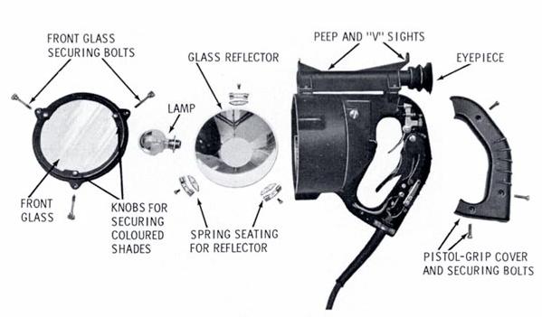 |
| Aldis Lantern, 5 inch - Principal parts. (Image courtesy
RCN) |
 |
| 5 inch Aldis Lantern - Cutaway side view. (Image
courtesy RCN) |
 |
| WRENS practicing with the Aldis lamp likely at
the training facility at St. Hyacinth. (DND Imaging Centre photo # 209639-1) |
Under what conditions were Aldis lantern used? Former signalman
Andy Barber explains. "We only used the Aldis lantern for short distances.
It was normally used aboard the motor cutter or whaler. That is how we
told out ship that we were coming alongside. It was also used on the small
duty boats for similar reasons. It was difficult to use the Aldis
lantern since the boats would be bobbing up and down with the waves. You
really had to keep it sighted on your target or the recipient would not
be able to read it. Personally, I found it to be a real pain but
it had to be done".
INTERMEDIATE AND OTHER LANTERNS
The Intermediate Lantern produces 2 to 2000 candlepower depending upon
the position of its control switch. When connected to a power source, the
lamp illuminates continuously although this is not apparent unless the
trigger is pressed. A sleeve of metal, which completely covers the lamp
is attached to the trigger. Morse code is generated by covering and uncovering
the lamp using the trigger. Since the lamp is normally covered by the metal
sleeve, it is also very easy to forget that the light is on so the operator
might store it while still switched on. Apart from potential damage caused
by overheating and the attendant fire hazard, leaving the lamp switched
on for extended periods of time required more frequent changes of the bulb.
A modernized version of this type of lantern is carried by HMC ships
in 2007. HMCS Toronto still has two Intermediate Lanterns on the bridge
for backup purposes.
AP1038 PORTABLE SIGNAL LIGHT (WWII ERA)
This device uses an Edison Mazda 1W 2V bulb, Patt 1039A and powered
by a rechargeable battery in a box slung beneath the instrument. It was
smaller than the Aldis Lamp and used for night-time convoy identification,
hence the reason for using a low power (1 watt) bulb. Internally, it has
sockets for 2 bulbs (one to hold a spare). The operator can select
one of five coloured lenses blue,/ red, green, white or clear.
In the RCN, it was used at close quarters but night time only.
 |
| AP1038 side view. The lens is on the
left side (Photo by Douglas Moore) |
 |
| AP1038 internal view. The spare bulb socket
is at the top centre. (Photo by Douglas Moore) |
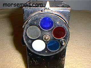 |
| AP1038 Front view of lenses. (Photo
courtesy morsemad.com) |
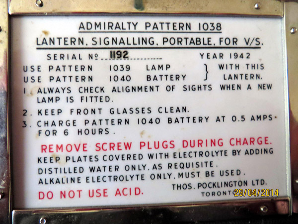 |
| AP1038 operator instruction plate. (Photo by
Douglas Moore) |
AP2174
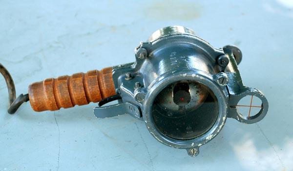 |
| Intermediate Lantern - Front view. The black
cylindrical object in front of the mirror is the shutter. It moves
forward when the trigger is engaged thus allowing light to escape. (Photo
by Jerry Proc) |
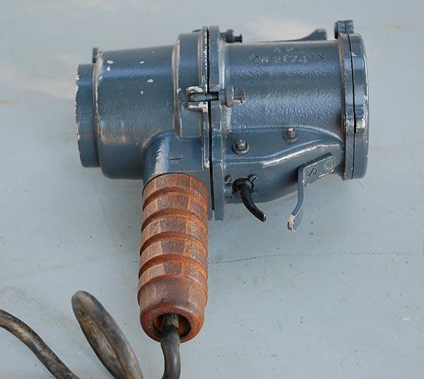 |
| Intermediate Lantern - Side view. Admiralty
Pattern Number AP2174. (Photo by Jerry Proc) |
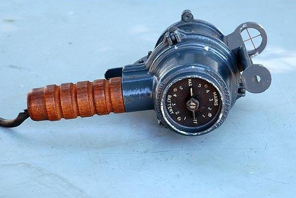 |
| Intermediate Lantern - Rear View. The control
dial selected the power source (mains or battery) and the light intensity
for each power source.
(Photo by Jerry Proc) |
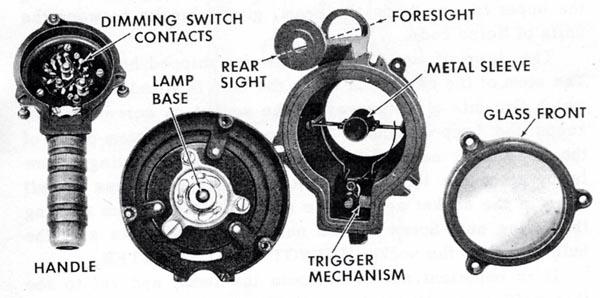 |
| An Intermediate Lantern disassembled into its principle
parts. (Photo courtesy RCN) |
DAYLIGHT SIGNALLING LANTERN
The Daylight Signalling lantern (DSL) was fitted in cruisers
(ie HMC's Ontario and Uganda) and larger ships and mounted in pairs on
the side of the mast, bridge or funnel. It was used for non-directional
signalling during daylight. DSL had a horizontal divergence of 200 degrees
and a vertical divergence of +/- 10 degrees. It's 25,000 candlepower output
gave it a range of several miles.Morse code was produced by the keying
of an electric shutter fitted inside the lantern. The shutter could be
keyed from several locations on the bridge or the flag deck of the ship.
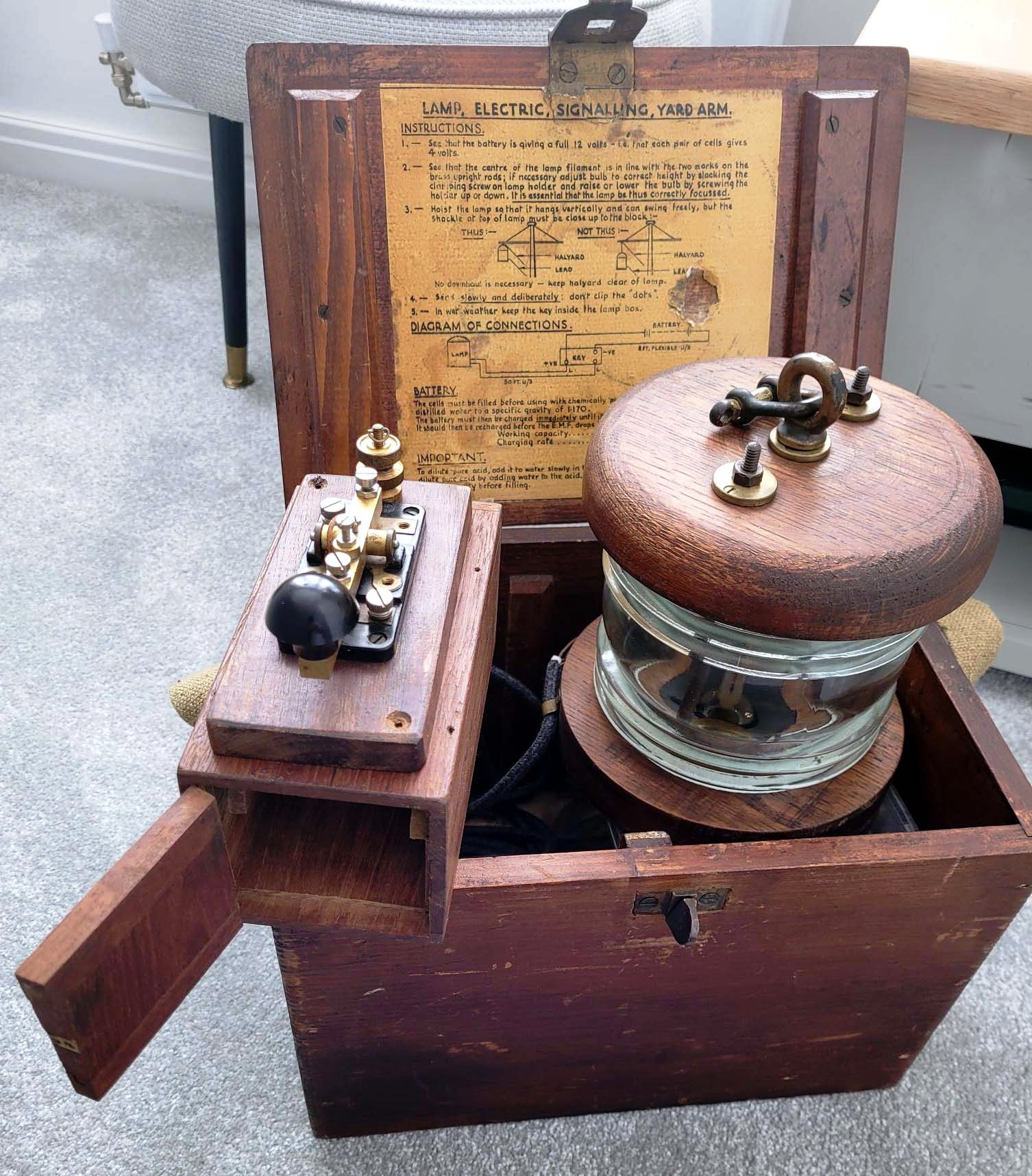
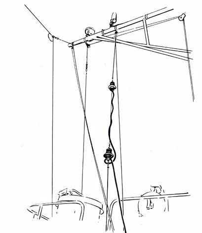
YARDARM MORSE SIGNALLING
At this time, there is no confirmation if the Yardarm Morse signalling
device was ever used in the RCN. There are however some thoughts on its
potential usage.
1) Smaller ships without convenient places for fixed attachments would
use a lamp that could be hoisted to the yardarm by a lanyard and
hoisted only when needed.
2) It could have been used for night communication when flag hoists
could not be seen.
3) It could be hauled down to clear the yardarm for flag hoists.
4) Replacing a burnt out bulb on a fixed yardarm fixture could be dangerous
in heavy seas.
Here is what the Morse lantern isn't:
* Not used by the Royal Navy. There was no Inglefield clip . The
RN would not have used a shackle.
* No Bunting Tosser has seen the likes of it.
* There was no A/P number.
If anyone can confirm when or where this device, was used, please contact
: jerry.proc@sympatico.ca
 |
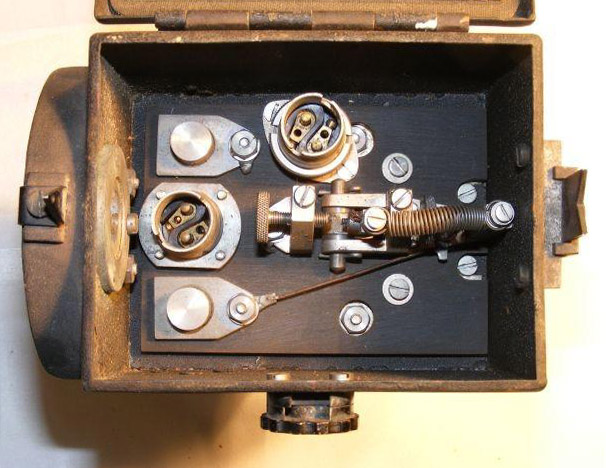
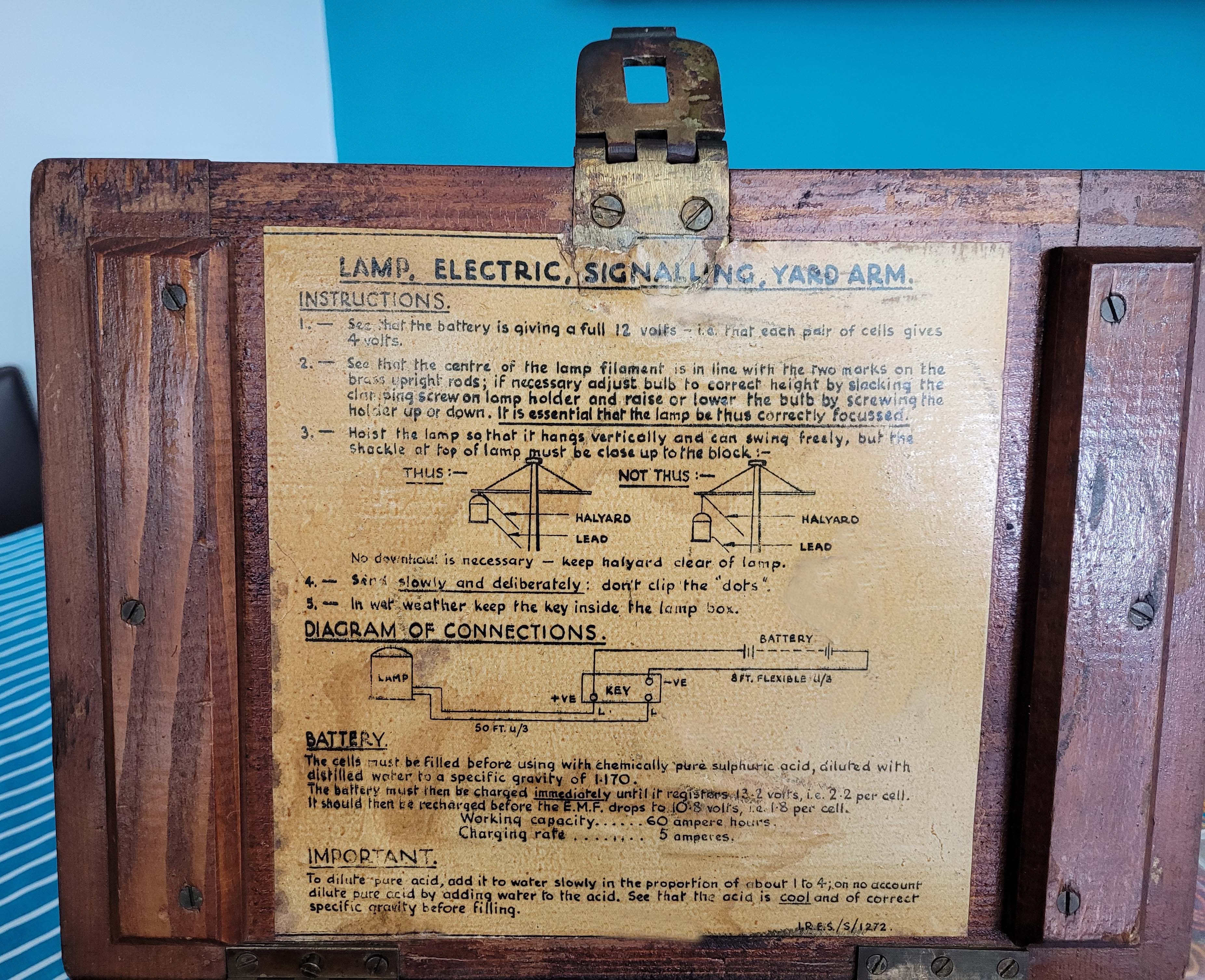 |
| The Morse signalling kit consists of a Morse key, a lamp and a carrying
case. A 12 volt battery is external to the device. |
Unobstructed view of the Instruction sheet. |
| Click on either image
to enlarge. |
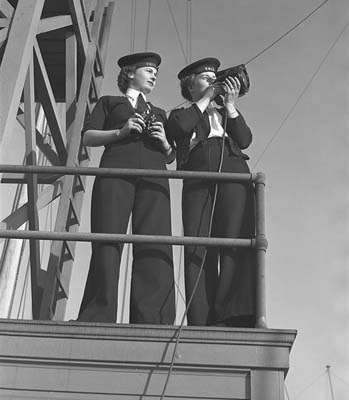
HEATHER SIGNALLING LANTERN AP 378
The Heather Lantern was a small signalling lantern designed to be attached
to the top of a pair of binoculars allowing the hand holding the binoculars
to also send Morse code. This was intended for use when ships were
"darkened' and not allowed to show any light. It was particularly useful
during night surface actions. The lantern was made as model 378A
and kater as 378B.
In Canada, one company which made the AP 378 was R E & R Co . (Renfrew
Electric and Refridgerator Co. Ltd. c 1944)
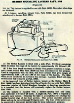 |
Click on thumbnail for additional details about
the Heather lantern. About 6.25 " long and 2" diameter. It has a Morse
key on the right hand side .(Image via (Maple Leaf Up) |
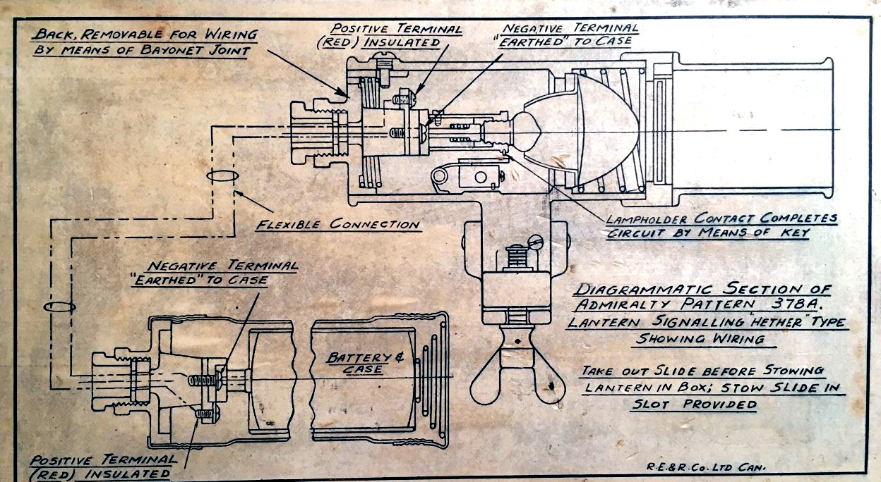 |
378A wiring diagram. Click on image to enlarge.
(Provided
by Ted Orlowski) |
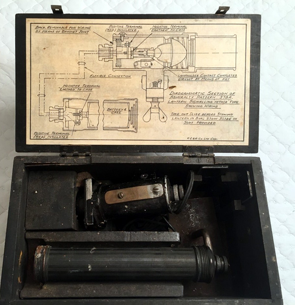 |
| Placement of filter holder and battery pack
inside the carrying case. |
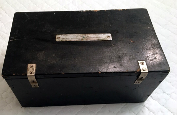 |
| Model 378A carrying case. |
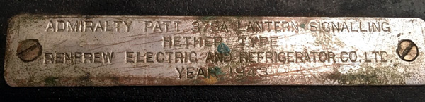 |
| Model 378A - nameplate on carrying case. |
| All photos in this table by Ted Orlowski |
 |
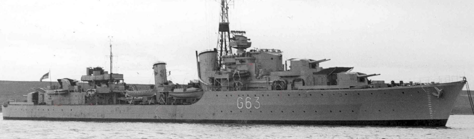
| The Hether lantern in use. (Getty Images) |
CONVOY LIGHT
If one looks very carefully at the stern of HMCS HAIDA, one
can see what used to be the remains of a glass window. In Tiller flats
there is a box coming away from the window with an ordinary light bulb.
It was on a dimmer controlled from the bridge. By having the light
that far in, it could only be seen if the observer was
in a perfect line with it. No illustration is available because the
window has been painted over.
MASTHEAD STEAMING LIGHT
At night, the Masthead Steaming light is part of Safety at Sea by using
different coloured lights in order to be seen by other vessels. It
was not used for signalling or navigation. The colour and the arc
of visibility displayed tell you ( the viewer) the direction in which
the vessel is heading - right, left or ahead.
These specifications for the lights are contained in
"Collision Regulations. International Regulations for Preventing
Collisions at Sea" Rule 23 states (in part) that a power driven
vessel underway shall exhibit:
" A Masthead Light visible forward for six miles.
This means it has to have a height of 30 feet above the
water. HAIDA's Masthead Steaming light is 45 to 50 feet above
the waterline, so its visible for eight miles".
There are a hundred different light configurations- fishing vessels,
towing, anchored, engaged in refueling. Knowing the meaning of the
lights is the trade of the Watchkeeping Officers.
 |
| The black square on HAIDA's foremast was the location of the Masthead
Steaming Light and the Fog Dodger. On the early lattice mast
it was positioned at the same height as the Crowsnest was on the tripod
mast. The Steaming light was also observed on HMCS Huron and other Tribals.
(RCN
photo provided by Darren Scannell) |
 |
| A closeup of the early lattice mast aboard HMCS Huron shows more
detail. Item #1 is the Masthead Steaming Light. Its arc is 110 degrees
on either side of centre but it was not used for signalling
or navigation. Click on image to enlarge. (RCN photo provided
by Darren Scannell)
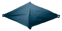
Item #2, known as a Fog Dodger, is a canvas shroud which could be white
or black. When transiting through fog, the Officer Of The Watch might dispatch
a lookout to this station. On-build, the Tribals had tripod masts
with a Crowsnest. When the tripod mast was converted to the
early lattice mast, the Crowsnest disappeared. The canvas shroud was rigged
for fog lookout and was meant to be there on a temporary basis. |
CLUSTER LIGHT
This was not a signalling light nor was it used for navigation.
It was used in daylight fog to provide a warning to ships approaching from
astern. The brightness of the light was controlled by a dimmer located
on the bridge.. Inside the fixture, there were eight bulbs and the fixture
was deep enough to keep the light from escaping out the sides. It
was also used to help a ship keep station astern while steaming. On HMCS
Cayuga's DND plans, the fixture is labelled as a 'Cluster Light'. Norman
Ough, British Naval Historian/Model Maker, labels it as a ' Fog Light'.
 |
| Mounted atop the Squid Handling Room on HMCS HAIDA,is the Cluster Light.
Click on image to enlarge. (Photo by Jerry Proc) |
NUC LIGHTS, BLACK BALLS and DIAMONDS
Not Under Command Lights
NUC (Note 2) lights are two red lights joined together by a six
foot length of wire rope or halyard. The condition means that the
ship cannot obey the "rules of the road" and all other ships must give
her the right of way. These lights were hoisted on a signal halyard during
the hours of darkness to indicate a breakdown or man overboard. They had
to be ready for instant use between sunset and sunrise. During daytime,
two black balls would be used to signal a NUC condition.
The Signalman of the Watch would test the lights to ensure they were
working properly then he would hoist them on the yardarm. When in position,
the Officer of The Watch was informed. When required, they
were turned on and left on to indicate a breakdown or flashed to indicate
man overboard.
Halifax class ships have red and white NUC lights built into the mast
to inform other ships of any of the following states: NUC, RAM (Restricted
in Ability to Manoeuver), Man Overboard (MOB) or prosecuting a sonar contact.
These lights are not optional as they are mandated by the International
Regulations for Preventing Collisions at sea (COL REGS).
 |
|
NUC lights. (Image courtesy RCN)
|
Two black balls, separated by tackline could be used by day to indicate
that a ship is Not Under Command. By night it was two vertical red
lights. A vessel at anchor would hoist one black ball on the yardarm
corresponding to the side on which her anchor is down. The anchor
ball is hoisted when the anchor is dropped and is hauled down when the
anchor is aweigh. Light on top of the jackstaff denotes anchored at night
plus the running lights would be off.
Diamonds are also carried so a ship can inform other ships of its status.
The pattern Blackball -Diamond- Blackball means - "Restricted in ability
to maneuver".
Theree blackballs means "I've run aground". Black balls are still carried
aboard HMC ships in 2007 since the carrying of shapes is also mandated
by COL REGS.
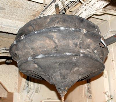 |
| This is a canvas black ball, the type used by the RCN in the 1960's.
This example aboard HMCS HAIDA is in a near petrified state after having
been stored outdoors for several decades until it was discovered in 2002.
Handled with care for the photo shoot, it was not forced to deploy to its
fully open position. Normally the top would be peaked like the bottom.
(Photo
by Jerry Proc) |
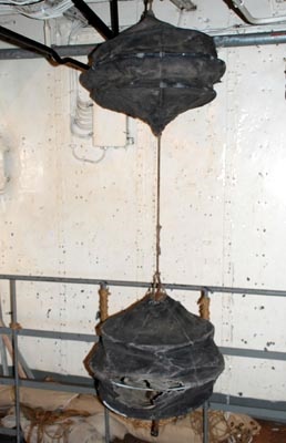 |
| Here's how two black balls looked when secured with regulation length
tackline. The bottom one is in a fairly deteriorated state. (Photo by
Jerry Proc) |
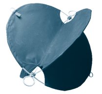 |
 |
| Commercial marine black ball. (Image courtesy Thomas Gunn Services) |
Commercial marine diamond. (Image courtesy Thomas Gunn Services) |
 |
| HMCS HAIDA: Situated on the bridge rail between segments of the
torpedo aiming/firing controls is a short pin used for holding a signalman's
board on which signals were clipped. The captain and the officer of the
watch could then read it at their convenience while the signalman read
another flashing light message. (Photo by Jerry Proc) |
SOME OPERATIONAL ASPECTS OF LIGHT SIGNALLING
The choice of which lantern or projector to use was generally left to
the operator's discretion. His choice would have been based on several
factors some of which are: distance, amount of daylight, sea state, presence
of other ships and background. Signalling at dusk and dawn was kept to
a minimum as this is a critical period when the ship's position could easily
be betrayed to an adversary by the display of lights. There was a requirement
to use a minimum amount of light for message transmission, hence the operator
may have to change from one piece of equipment to another as circumstances
dictate.
It was also possible to reduce the brilliancy of a lantern after communications
were established. If the light output from a sending ship was too brilliant,
the receiving ship would sent a series of 'D' characters until the sending
ship reduced the brilliancy of its light.
The special abbreviation OL was used to tell the receiving station to
show a steady dim light. This was done at night when using small directional
flashing lanterns which must be accurately trained in order to be seen.
If reception became difficult owing to a badly aimed or poor light, the
receiving station was expected to flash a series of 'W' characters whereupon
the sender was expected to direct a steady beam of light until the letter
'K' (meaning proceed) was received. For signalling to one station only,
a directional lantern was generally used.
Directional procedure is a method which requires each group (word, prosign,
code group, or operating signal to be acknowledged by a flash from the
receiving station before the next group is transmitted. Should the receiving
station miss a group, it was repeated by the transmitter as often as necessary
until a flash was received.
Now... fast forward to 2007 and a comment from a current serving NAV
COMM describing his Halifax class ship. "We have two yardarm blinkers,
one at each end. Keying boxes for the light are found on the bridge and
on the bridge wings. Yardarm blinkers are used for Non-directional light
sending of a large message. Non-directional protocol is complicated and
few if any navies use them as a method of sending signals. Generally, messages
are send via teletype or satellite. Visual Comms is used for short tactical
signals or operator to operator short messages. Directional signalling
with lanterns is far superior and less prone to error".
MODERN INTERMEDIATE LANTERN
The primary small signaling lantern in the Canadian Navy circa 2007
is the Wiska Richtblinker RBL available from Rainer Förtig Elektronik
. It is a plastic, battery operated signaling gun with interchangeable
colour filters. In the Canadian Navy, it's referred to as the Wiska lantern.
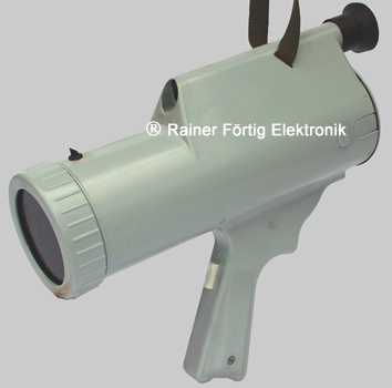 |
| Powered by battery, the Wiska Richtblinker RBL has a 70 mm wide lens
and a focal length of 30 mm. It uses a 4 V, 0.75 amp projection lamp and
weights about 1.0 kg. (Photo courtesy Rainer Förtig Elektronik) |
TRAINING
John MacFarlane recalls his training at Cornwallis.
" I remember that Morse visual training was conducted with a lamp for the
first year UNTD cadets at Cornwallis. A projector was mounted on the outside
of the second floor of the H-hut which housed the Gunroom and classrooms.
Cadets would stand in the courtyard one with a clipboard with back turned
to the lamp and the other softly calling out the letters or numbers which
were duly recorded. All cadets had to qualify regardless of the number
of attempts necessary to pass. The speed was probably 5 wpm which was
easy for me but perplexed many of my colleagues.
Once I passed the test on the first try, I was delegated to transcribe
for all the other testers. Typically some of them just didnt get it
so I would stand so that I could see the lamp reflected in a window. Of
course the copy is same either way so I simply recorded the message and
passed numerous shipmates who would never have passed otherwise. That was
good for rounds of beer in the Gunroom and elevated my popularity. Eventually
the instructors began to suspect me and I was forced to move to another
location which put me out of business. I know, I should be ashamed
but it still brings a chuckle!
We were not required to send but I was employed in Gate Vessels as
a Cadet visual communicator and got practice at sea sending and receiving
which I enjoyed thoroughly. The lamp however hobbled me in learning to
send CW on radio and it took some time to forget the visual decoding
mental process! In our Second Year training, we did no more visual signalling.
It was all voice procedure and fleet manoeuvres which was not as much fun".
FOOTNOTES:
[1] Metropolitan-Vickers, Metrovick, or Metrovicks, was a British heavy
electrical engineering company of the early-to-mid 20th century formerly
known as British Westinghouse. Highly diversified, they were particularly
well known for their industrial electrical equipment such as generators,
steam turbines, switchgear, transformers, electronics and railway traction
equipment.
[2] Rule 3 of the Colregs (International Regulations for the Prevention
of Collisions at Sea) provides this definition for a vessel not under command:
The term "vessel not under command" means a vessel which through some exceptional
circumstance, is unable to maneuver as required by these Rules and is therefore
unable to keep out of the way of another vessel.
OTHER READING
Please refer to the Morsemad
web page which features visual light signalling.
Contributors and Credits:
1) James McAlister <themcalisters(at)sympatico.ca>
2) Spud Roscoe <spudroscoe(at)eastlink.ca>
3) Douglas Moore, Cornwallis Museum <cornwallismuseum(at)yahoo.com>
4) HMCS HAIDA Staff Resource Manual 2003
5) Don Wagner <navwags(at)hotmail.com>
6) Morsemad web page http://www.morsemad.com/lamps.htm
7) Jim Brewer <snack.235(at)sympatico.ca>
8) http://en.wikipedia.org/wiki/Metropolitan-Vickers
9) http://www.answers.com/topic/signal-lamp
10) Richard Dillman <ddillman(at)igc.org>
11) Signalman Trade Group One Manual BRCN 3038(63). Published
by RCN, 1960; revised 1963.
12) PO1 JR Stroud, Senior Nav Comm, HMCS Toronto <stroud.r(at)forces.gc.ca>
13) CPO2 Derrick Shillington. HMCS Toronto Combat /Training
Chief <shillington.c2(at)forces.gc.ca
14) Thomas Gunn Navigation Services http://www.thomasgunn.com/products/pages/sqlTest6.asp?Code=EQ09
15) Robert Willson RCN (Ret'd) <rawillson(at)rogers.com>
16) Richtblinker RBL image http://www.rainer-foertig.de/Beleuchtung.htm
17) Elsa Lessard <elsal(at)rogers.com>
18) John MacFarlane <John.MacFarlane(at)metrovancouver.org>
19) Don Ross <ddwross213(at)hurontel.on.ca>
20) Roma Kuzhlev <romakuzhlev(at)hotmail.com>
21) Heather http://www.morsemad.com/lamps.htm
22) Heather Erling Baldorf <scottishbaldorf(at)gmail.co>
23) Heather http://www.mapleleafup.net/forums/showthread.php?t=29368
24) Projector training aid - Ted Orlowski
<tborlowski(at)hotmail.com>
25) Morese Yardarm device <chris_cckl(at)ntlworld.com?
26) Peter Dixon, HMCS HAIDA Historian
Back to Visual Signalling
Mar 13/24