AN/ARN-6 Radio Compass
This is an Automatic Direction Finding receiver, which covers
100 KHz to 1750 KHz in four bands. The equipment can be used a radio compass
or other stations can be monitored to obtain weather reports or it may
be used as a communications receiver.
A BFO is used with the equipment in Antenna or Loop operation.
A fixed frequency of 455.9 KHz is used for band 1 and 143.4 KHz for bands
2, 3, and 4. A tone oscillator is used when the equipment is used in Compass
operation mode . The tone oscillator is set for 900 Hz and modulates the
CW signal as is passes through the IF stages.
Frequency Range:
Band 1 100- 200 kHz (IF = 465 KHz)
Band 2 200- 410 kHz (IF = 142.5
KHz)
Band 3 410- 850 kHz (IF = 142.5
KHz)
Band 4 850-1750 kHz (IF = 142.5 KHz)
Power Input: 26.5 VDC at 4.0 amps.
Weight: 60 lb for a complete system.
Receiver Dimensions and Weight: 7 5/16H x 11 3/8W x 15 7/16 D ; 34.75
pounds
Manufacturer: Bendix or Magnavox Company, Ft Wayne, Indiana,
USA.
Circa: 1950
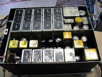
PRINCIPAL COMPONENTS OF ARN-6
 |
| AN/ARN-6 principal components. Mounting
MT-273/ARN-6 is an aluminum frame with a built in junction board
and a control switch relay at the base. MT-274 is identical to MT-273 except
that the control relay is not included. This is the mounting for single
remote control applications. Mounting MT-275 is a rectangular shaped
aluminum box with an open top into which the control box mounts. (US
Navy pictorial via HNSA) |
CONTROL BOX
Control Box C-149/ARN-6 is a rectangular shaped aluminum box
with the necessary circuit elements and controls for complete control of
the radio compass unit. That is the unit depicted in the principal components
pictorial. C1514/A below, is the control box which lacks the S-meter. There
were at least 3 control panels that were a standard cockpit mounting system
(a standardized panel system like the 19 inch rack) and one stand alone
control box.
 |
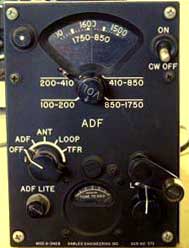
| C-1514/A rack mount control panel. This was the
version of control panel fitted on the Argus. (Courtesy Google
books) |
 |
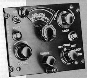
| Another style of control panel made by Gables. Not used in Argus. Shown
for reference only. (Photo by John Mackesy VK3XAO) |
RADIO COMPASS UNIT
Radio Compass unit R101/ARN-6 is contained within an aluminum
housing with removable top and bottom covers. It is comprised of the compass
circuit, a 16 tube superheterodyne receiver, the automatic loop control
circuit and the vibrator power supply unit. Tube lineup: 6 x 12SK7, 1 x
12SY7, 1 x 12SW7, 4 x 12SX7GT, 2 x 26A7GT and 2 x 2050.
The vibrator/transformer power supply produces AC for the 2050
thyratrons and the autosyn loop position transmission and indication system.
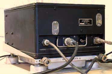 |
| R101/ARN-6 receiver on an MT-273 mount. |
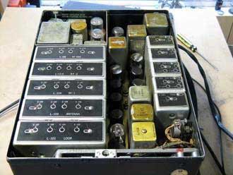 |
| Cover off front view. |
 |
| Cover off - side view. |
|
All photos in this table by John Mackesy VK3XAO
|
LOOP ANTENNA
Loop antenna AS313/ARN-6 is an iron core loop which is rotated by a
drive motor through a reducing gear train. A compensator, which can be
adjusted externally, is used to correct for radio compass deviation error.
An autosyn transmitter is geared through the compensator to the rotatable
loop and supplies loop position information to the remote indicator system.
The entire loop unit is sealed and filled with dry nitrogen. It cannot
be opened without special equipment. Electrically speaking, the loop antenna
uses a low impedance iron core loop of nine turns, is electrically centre-tapped
by means of a shunt coil of 12 turns and electrostatically shielded. It
is directional in that the voltage induced in the loop is maximum when
the line of travel of the received radio wave lies in the plane of the
loop coil . The resultant voltage induced in the loop in the loop is 90
degrees out of phase with the non-directional antenna and leads or lags
according to which edge the loop coil is nearer to the signal source.
Sense antenna- The non-directional antenna input circuit of the receiver
is designed to operate from a low capacity transmission line connected
through the proper matching circuit to a conventional 40 to 1000 picofarad
antenna having an effective height of from 0.05 to .5 meter.
Coupling Unit CU-65/ARN-6 provides a female connector for the antenna
transmission line and an antenna input terminal.
 |
| AS-313/ARN-6 loop antenna without radome. This
is a compact servo-operated directional loop aerial sealed into a nitrogen-filled
glass-topped housing. (Antenna photo courtesy BPB Surplus) |
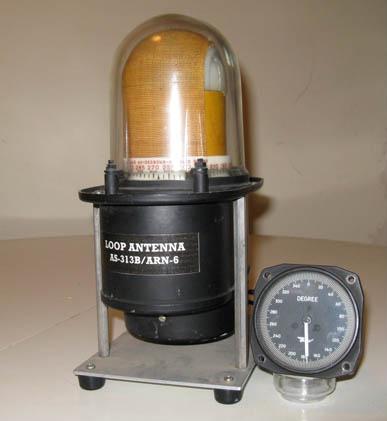 |
| AS313/ARN6 in test jig with indicator. (Photo by John Mackesy VK3XAO) |
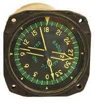
INDICATORS
ID-90/ARN-6 is an autosyn driven device which indicates the
angular position of the autosyn transmitter located in the loop and gives
the bearing of a radio transmitter when the loop is at a true null. It
does not have luminescent materials on the pointer and numerals. (3.25
inches square x 5 13/16 inches deep; Weight is 2.1 lbs)
ID-91/ARN-6 is identical to ID90/ARN-6 but it uses luminescent materials
on the pointer and numerals. (3.25 inches square x 5 13/16 inches deep;
Weight is 2.1 lbs)
ID-92 /ARN-6 is similar to indicator ID90/ARN-6 except that a larger
scale is used. The scale is graduated every degree and every 10 degree
graduation is indicated by the proper numeral. (3.25 inches square x 5
13/16 inches deep; Weight is 2.1 lbs)
ID231/ARN-6 is identical to indicator ID90/ARN-6 except that the pointer
is set at 270 degrees azimuth when the indicator rotor is at its electrical
zero position. This indicator is only used in special installations which
require the loop to be mounted with its zero heading at 270 degrees.
(5.5 inches square x 6 inches deep; Weight is 3.06 lbs)
 |
| This is the ID91B/ARN-6 indicator, one of four types available for
the system. (Photo by John Mackesy VK3XAO) |
 |
Also available was the dual pointer Type ID-250/ARN
indicator. 3-1/8" size . Made by Bendix Aviation Corp.(Photo by
John Mackesy VK3XAO) |
The Course Indicator (now called Radio Magnetic Indicator or
RMI ) ID-250 has 3 synchro motors. One rotates the compass dial card such
that the flight direction is on top, Pointer 1 can be connected to the
differential synchro from an ID-307 which then points in the direction
of the TACAN beacon. Pointer 2 can point to a VHF OmniRange beacon (VOR)
or an automatic direction finder (ADF) through a suitable receiver. This
was not fitted in the Argus aircraft.
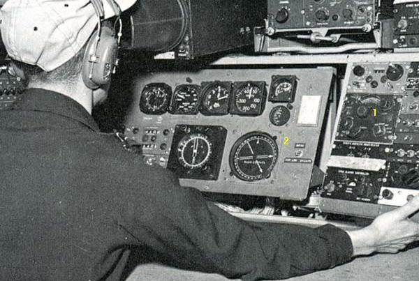 |
| Item 1 is the ARN-6 radio compass control panel at the Routine Navigator's
position. The Argus, did not use the standard ID-91 indicator. Instead
it was displayed on the ADF/OPTI instrument as item 2 above. (Photo
from Sentinel Magazine, May 1968) |
MANUAL
 |
| AN 16-30/ARN-6 manual. (Courtesy Lostpaper.com) |
Use Back Function to Return To Document
Credits and References:
1) ARN-6 antenna: BPB Surplus http://www.bpbsurplus.com/lc/cart.php?target=product&product_id=17071&category_id=341
2) Ian Snow RCAF/CF retired.<va3qt-4(at)sympatico.ca>
3) John Mackesy VK3XAO <mack(at)melbpc.org.au>
4) AN/ARN-6 Summary http://www.hnsa.org/doc/ecat/cat-0033.htm
5) ARN-6 manual photo http://lostpaper.com/toshop/index.php?main_page=popup_image&pID=5953
6) ARN-6 info http://www.vk2bv.org/museum/arn6.htm
7) ARN-6 info http://mcgp.cellmail.com/database/back%20mail/Backmails/MCGP%20Backmail%2037.htm
8) Tom Brent <tgb@telus.net>
Mar 5/10