|
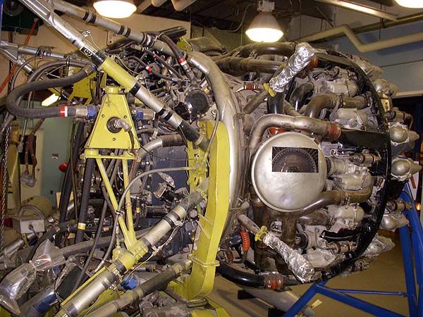
| Front view of engine. At the Flight Engineer's station, there was a spark plug analyzer in the upper right corner of the main panel. The FE could "look at" each spark plug individually to see if it was firing properly. There were 36 of them in total, two for each cylinder. |
 |
| Two power recovery turbines are evident in this view. Ian Snow explains the use of the supercharger. "In my experience, if we were crossing the Rockies and were going above 10,000 feet, the turbocharger would be used. Flashing up the supercharger was always a very precise exercise. It had high and low blower settings. Because it was used so infrequently, the flight engineer and pilot double checked, then rechecked their checklists to make sure it was done properly". |
 |
| The back of the engine is at the left of the photo. There was a power takeoff to drive a "quick disconnect unit" which in turn drove the generator. This was introduced in the late 1960's as a means of shutting down the generator without having to shut down the engine. There was one incident where the quick-disconnect unit disintergrated and tore everything apart behind the engine. |
| This example of an Argus engine can be seen at the Greenwood Aviation Museum. (All photos in this table by Robert Langille). |
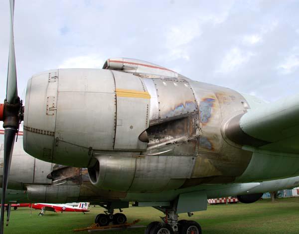 |
| The positioning of the exhaust stack on the R-3350 engine causes the hot gases to produce a colourful pattern on the stainless steel casing. (Photo by Jerry Proc) |
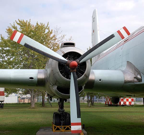 |
| Propellor detail. Note the deicers on the leading edge of the propellor blades. The doors on the front of the oil cooler were controllable and the FE set them to control engine temperature. Argus had slightly more than one ton of engine oil aboard! (Photo by Jerry Proc) |
John Mackesy, a former Aero Engine Technician, spent most of the 1960's working on Argus engines at Summerside PEI. He provides a detailed description of the Argus R3350 engines.
General
The Argus was powered by 4 x R3350 981 TC18 EA1 air-cooled radial engines, each 3700 HP (wet) take-off power at 2900 RPM and 59.5 Hg MAP. (MAP Manifold Absolute Pressure in inches of mercury (Hg), where 0 equals a perfect vacuum and 29.95 Hg equals a standard day (14.7 PSI)
Wet power refers to the use of Anti Detonation Injection fluid (ADI), a 60/40 mix of water and methanol plus 1% oil. Dry power was 3400 HP and used a very rich mixture, thus incurring a significant fuel consumption hit.
A bare engine weighed about 3400 lb, but when fitted with ring mount, cowling and oil cooler a Quick Engine Change unit (QEC) was about 5,000 lb. This was attached to the firewall by 4 stout bolts. When on the ground only the top 2 bolts took any weight. Dynafocal engine mounts used.
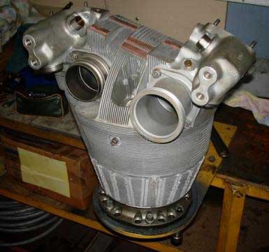
Cylinders
The R3350 had 18 cylinders in 2 rows of 9. Bore and stroke were 6.125 x 6.312. The cylinders had nitrided steel barrels and forged aluminum alloy heads. The cooling fins were sawn into the heads and the heads were screwed and shrunk onto the barrels. Cylinders were attached to the steel crankcase by short bolts around the base of the cylinder (very awkward to get at, special wrenches required). Compression ratio was 6.7:1; 3 wedge-type compression rings and 2 oil rings were fitted. Bayonet-type thermocouple cylinder-head temp sensors were fitted to #7 & #8 cylinders. Master rods were located in #1 (top rear row) and #2 (top front row) cylinders; there were piston cooling nozzles, 1 per cylinder except the master rod cylinders, which had 2.
Valve Operation
Push-rod OHV with roller cam followers, 2 valves per cylinder, both sodium cooled. There were 2 cam rings driven at 1/8 crankshaft speed in the opposite direction to the crankshaft, each with 2 tracks (inlet and exhaust) and 4 lobes; valve timing was different front vs. rear row to compensate for the better scavenging of the rear row. To improve front row scavenging, aspirators were fitted to front row exhaust pipes. These could come loose and migrate into a power recovery turbine, jamming it. It was a good policy to give the turbines a spin before flight, if possible. To check valve clearances it was necessary to measure the clearance on each flat of the cam ring (4), take an average and use that to derive any adjustment required. In service, valve adjustment was rarely required.
Supercharger
A single stage 2-speed supercharger was fitted with ratios of 6.46 x crankshaft speed (low blower) and 8.67 in high blower. High blower was only used above 10,000 feet and the speed change was effected by a multidisc clutch operated by engine oil pressure. When changing blower speed it was necessary to reduce engine speed below 1600 RPM. When the clutch was operated, the oil pressure would dip momentarily (oil light would blink). There was an electrically-operated supercharger shift valve at the bottom centre of the engine. High blower was rarely used, except when flying through the Rockies, when it was not uncommon for one engine to remain in low blower.
From distant memory, the blower absorbed 180 HP in low blower, 260 HP in high blower.
Power Recovery Turbines
There were 3 Power Recovery Turbines, which extracted up to 600 HP from the exhaust stream, feeding it back to crankshaft via reduction gearing and fluid couplings. The fluid couplings served to isolate vibrations between the crankshaft and turbines. These couplings drained when the engine was static, to reduce loads on the starter when cranking. Each turbine disc was drilled in 4 places, so in the event of a turbine overspeed (24,000 RPM) it would break into 4 relatively small pieces. An armoured band on the PRT hood (exhaust stack) prevented escape of turbine parts. Use of power recovery turbines gave a 20% reduction in fuel consumption vs. a non-compounded engine for very little increase in bulk and weight and were totally automatic in operation.
Fuel Injection
A Stromberg PR58S-2 Fuel master control unit (FMCU) was fitted to the top/rear of the engine, controlling fuel flow to 2 Bendix DLN-9 (?) variable-cutoff injection pumps. Direct injection was used, the injectors being fitted to the front of the cylinder heads. The left-hand pump served the rear cylinders, the right-hand the front cylinders. These pumps were marked with a white P, indicating polarised, larger oilways for cold-weather operation.
Ignition
Bendix low-tension ignition, consisting of a dual magneto-generator, 2 distributors and a double ignition transformer on each cylinder head. The magneto-generator, mounted at top rear of the engine generated 300V pulses which were fed to the distributors mounted on the top of the nose case. Left distributor, rear plugs, right distributor front plugs. The distributors contained carbon brushes in contact with a pair of co-planar slip rings. 2 plugs per cylinder, typically AC 275 or Lodge RS35-2RS (?) Could also use Champion RHB29P(?). Lodge had the longest life, AC were inclined to seize in the stainless-steel spark plug thread inserts. There were 2 timing settings, controlled from the FEs station, retard (25° BTDC) and advance (30°) BTDC. Advance was used in economy cruise mode.
An ignition analyzer, either Bendix type 11-3350 or 11-4360 was fitted at the flight engineers station. Horizontal sweep was initiated by a sync breaker on the lower left and side of the engines accessory drive section.
The R3350 firing order is: 1-10-5-14-9-18-13-4-17-8-3-12-7-16-11-2-15-6
Propeller
Propeller reduction gearing was .4375:1 (16:9) and a torquemeter (transmission dynamometer) was incorporated in the reduction gearing. Curtiss Electric 3-blade 156 feathering and reversible props were used. Each prop weighed about 700 lb (I think). Prop pitch was controlled by an electric motor driving an 8000:1 planetary reduction gearbox driving a large ring gear. This ring gear engaged a segment gear on each blade. There was an electrically-operated disc brake associated with the pitch motor, its operating solenoid in series with the motor. This brake was normally on and would only release when a pitch change was commanded. The disc could wear and cause the RPM to wander, but was easily replaced. There was a low pitch stop mechanism which would lock up the pitch control to prevent a runaway prop situation. This was electrically retracted when reverse pitch was selected. When the prop was fully in reverse pitch, the reverse pitch tel lights would illuminate, throttle stops would retract and it was possible the pull the throttles back. About 2600 HP was available in reverse.
When feather or reverse was actuated, dynamotors increased the prop pitch motor voltage from the normal 28V to 72V for quicker operation. Feathering buttons each had a red light in the centre, actuated by the negative torque switch located on the engine mount, so there was no chance of feathering the wrong engine. When an engine was feathered, fuel, oil and ADI were automatically shut off.
Accessory Drives
There were a number of accessory drive pads on the engine rear cover, one of which was used to drive a Sundstrand 45GBO2 hydromechanical constant speed drive (CSD), located in a compartment behind the firewall, via a short universally-jointed drive shaft (CSD shaft). The pad that drove this rotated at 3.11 x crankshaft speed CCW, and was fitted with a torque limiting clutch to protect the engine gears from excessive loads. These were later replaced with electrically-operated CSD disconnect clutches, which meant it wasnt necessary to feather an engine in the event of a CSD failure. There was also a quill shaft in the system, which would shear if the engine accelerated too rapidly when starting.
Electrical
Each CSD (4) drove a 40 KVA 115/208V 400 Hz 3-phase alternator at 6025 RPM. A frequency and load controller kept everything in step. The 2 inboard CSDs were fitted with hydraulic pumps, driven by a 5 HP pad on the CSD. The CSD was rated at 65 HP. There was a sprag clutch on the CSD input to allow the CSD + alternator to coast down when the engine stopped. These would occasionally for no obvious reason fail to engage when the engine was started, but would usually come in after several tries. There were CSD oil coolers in the leading edge of the wings. 27.5V DC power was supplied by 4 x 200A Transformer Rectifier Units (TRUs). Argus engines were fitted with heavy-duty direct-cranking starters with an integral torque limiting clutch.
Oil System
There was a 56 Imp. gal. oil tank for each engine (no crossfeed). Each tank contained a small-volume hopper tank through which oil circulated until it warmed up; oil circulation through the tank was controlled by the segregator-diverter valve. Oil temp was controlled by a thermostatic floating control switch that controlled the oil-cooler air exit doors. Normal oil consumption for a well broken in engine was about 1 ½ Imp GPH. Aeroshell W100 ashless dispersant oil was used. Lubrication was by a 2-section pressure pump and a 3-section scavenge pump. There was also a scavenge pump in the front sump, serving the nose section. 2 oil filters, a piggyback pressure filter fitted on the rear sump and a remotely-mounted scavenge filter.
Like most radial engines, the Argus R3350 had a tendency to spit oil when starting and to drip when stationary, blackening aprons far and wide. When in the hangar, drip trays were a must. At flight speeds, a little oil goes a long way and the many small leak points around the engines kept the surrounding areas corrosion inhibited.
Webmaster's note: John currently lives in Australia and licensed as VK3XAO. His current passion is restoring and operating avionics.
Ian Snow comments on the Argus engine. "As I recall there was quite a rush to fix the CSD unit "quill shaft" problem. If it sheared in flight it would flail about severing all manner of lines and cables with the disconnect unit. As I recall there were two shafts, one splined and inside the other with a universal joint at each end. This was to allow for engine movement since the CSD was hard mounted in the nacelle. At this point I don't recall what the problem was except that either the two shafts separated or more likely the universal joint on the CSD unit separated. When I first got to 415 Squadron, the generators where coupled directly to the engine so if there was a generator issue the Flight Engineer caged the engine and we were forced to go home. Being able to disconnect the generator removed that obligation - in theory. After a couple of scary incidents (i.e. severed lines and who knew what being pumped all over the interior of the nacelle, arcing wires, etc.) there was a lot of grass roots pressure to get rid of the CSDs. After all, the number of times a generator failed were very low.
To say that the old girl had power to spare was an understatement. Loosing one generator had no effect on the mission and I think the consequences of loosing even a second one were relatively minor. Of course after loosing two (I don't know if it ever happened) I'm sure there would have been an immediate requirement to head for home."