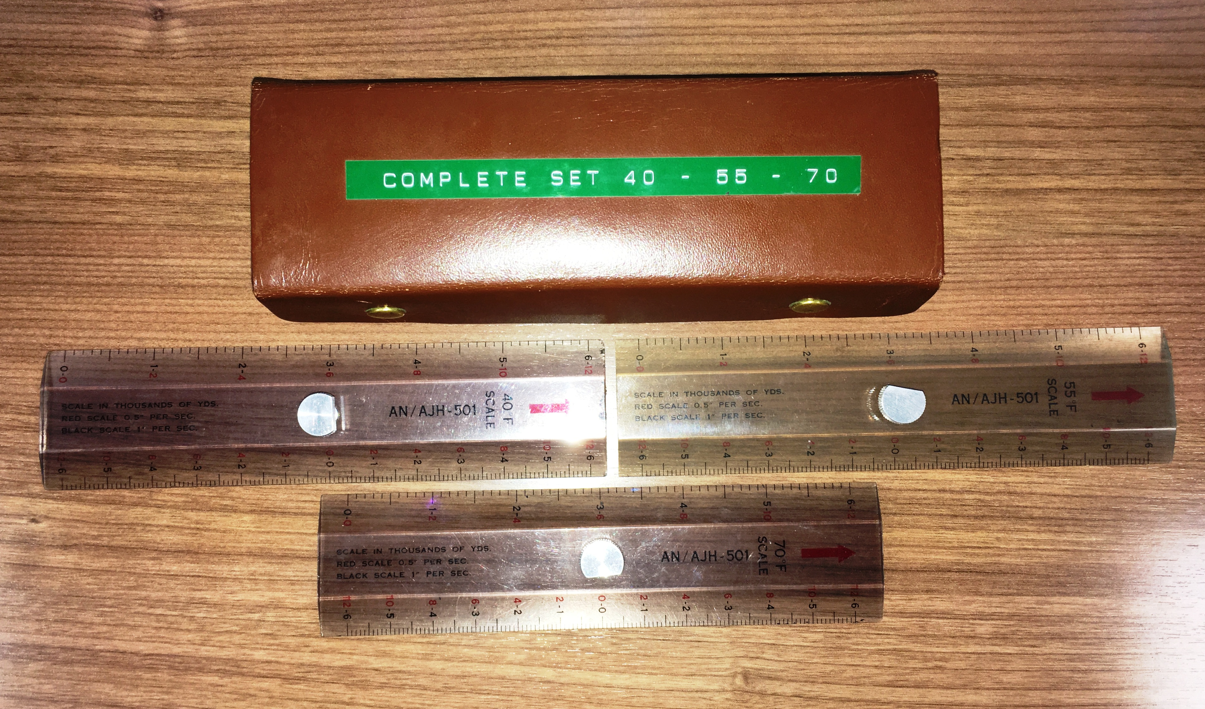 |
| Julie ruler set for AN/AJH-501. Download image to enlarge. (Photo by Tim Cathcart) |
With such a huge proliferation of electronics aboard the Argus and changing over time, it is very difficult to compile accurate fits for a particular era. The electronics listed in the table was NOT fitted simultaneously but when known, the various pieces of gear of identical function are listed chronologically.
| ELECTRONICS MANIFEST | |
|
|
|
| AN/ARC-38 | Aircraft Transceiver. Frequency range: 2 to 25 MHz . Modes: A1, A3. Power output: 100 w. Frequency Control: VFO control with 20 channel autotune. The AN/ARC-38A added SSB capability. Weight 138 lbs. Used for Liason Communications. (Photo by John Mackesy VK3XAO) |
| Collins
618T/
ARC-505 |
HF transceiver. Frequency Range: 2-29.999 MHz in 1 KHz steps. Modes: AM, CW, USB, LSB, Data. Power requirements: 28VDC or 115 VAC 400 Hz. Power Output AM/CW: 125W. SSB: 400W PEP (Photo by John Mackesy VK3XAO) |
| CU-351/AR | HF antenna tuner - Provides automatic tuning of fixed aircraft antennas and efficient transfer of RF power from the 52 ohm output of a 50-150 watt transmitter into such antennas. It consists of two motor driven ceramic rollers and a variable capacitor in a sealed glass envelop similar to an EIMAC tube, with pins on the bottom to fit into a socket. A long, flat silver plated wire was reeled between the rollers to change the inductance. Circa 1956. (Photo by John Mackesy VK3XAO) |
| AN/ARC-502 | VHF- Command Communications. A 24 channel version of the American 8-channel ARC-3. 100 to 156 MHz. 8 watts. Early versions of the Argus had two VHF antennas installed in close proximity to each other. |
| AN/ARC-506 | VHF Command Communications. A solid-state replacement for the ARC-502. It was a 360 channel system that had DF capabilities when used in conjunction with the ARA-8 VHF Homer. Frequency range 118.0 135.95 Mc, 50 KHz frequency intervals and 25 watts minimum power output. No photo available. |
| ARC-552 | UHF- Command Communications. Receiver/Transmitter; 225 to 400 MHz with independent Guard receiver for 243 MHz. Power output: 20 watts average. (Photo courtesy RCN) |
| AN/AIC-10 | Aircraft intercommunications. The AIC-10 was introduced in 1953 by the USAF as a new standard for Aircraft Interphone Communications. Manufactured by Andrea Radio Corp or Radio Corporation of America. Pictured here is a 5 position C-826/AIC-10 control panel but the Argus used a 10 position panel sd evident from photos. It was mounted at all stations in the aircraft. As a secondary function, it could be used to listen to the ADF. There was an overhead monitor speaker at the galley table. (Photo courtesy E-bay) |
|
|
|
| AN/APN-70 | Loran 'A' receiver and manufactured by Dayton Aviation Radio & Equip Corp. Loran A was used aboard the Argus initially, then switching over to Omega. At one point, both receivers were installed. Loran 'A' closed in 1980 just as the aircraft was being taken out of service. Omega closed in 1997. |
| AN/ARA-8 | VHF Homing Adapter for ADF receiver. (Circa 1945). The ADF receiver was used to home VHF beacons placed along air routes and at airports. On the Argus there was a wire antenna for listening/tuning the beacon and a DF antenna . It had a footprint the size of one's hand, 6" tall and located under the long blister atop the Argus. Pictured is the control panel for the ARA-8. (Photo courtesy Tailwheel.NL) |
| AN/ARA-25 | UHF Homing adapter. Requires UHF radio capable of 225-400 MHz reception. Modes: A2, A3. Circa 1952. |
| AN/ARN-501 | TACAN (TACtical Air Navigation) |
| AN/ARN-5 | ILS glide slope receiver for 332.6, 333.8 and 335.0 MHz.
Originally designed in 1944. This was a later fitting on the Argus.
AN/ARN-5 antenna photo. (Mac's Naval Photography) |
| BC-733D | Localizer Receiver, 108.3-110.3 MHz, crystal-controlled, 14-28 V. Made by Western Electric, Crosley and others for the RC-103 blind landing system. Used with I-101 indicator, R-57/ARN-5 and R-89/ARN-5A. (Photo courtesy E-bay, Italy) |
| MN53B | Marker Beacon Receiver. Made by Raytheon of Baltimore MD. Marker beacons were ground transmitters with a vertically polarized antenna. They are seen at the end of the runway - a small shelter with a 5 or 6 element yagi pointed straight up. Others would be placed at a point extended down the runway line to the point where the pilot should begin his descent |
| AN/ARN-6 | Radio Compass. Manufactured by Bendix. 100-1750 KHz. Requires ARN-6 loop antenna. |
| AN/APN-22 | Radar Altimeter. Operates on FM between 4200 to 4400 MHz,
0 to 10000 feet over land. Up to 20,000 feet over water. Transmitter Power
Output: 1w nominal.
Accuracy: ± 2 ft from 0 to 40 ft; + 5% of the correct terrain clearance from 40 to 20,000 ft. Manufactured by Electronic Assistance Corp. Because the Argus routinely flew at altitudes of 300 feet or less, a radar altimeter was necessary part of the kit. A reliability circuit disabled the indicator when the signal is too weak to provide reliable operation. Main units consist of an Electronic Control Amplifier AM-291/APN-22, Height Indicator ID-257/APN-22, Radar Receiver-Transmitter RT-160/APN-22 |
| AN/ARN-509 (V) | OMEGA - A 100 KHz radionavigation system which was shut
down in 1997.
Photo of front panel.
|
| B6 Drift Meter | See explanation below this table, |
| TACTICAL | |
| AN/APS-20E | S-Band (2880 MHz +/- 30 MHz) search radar. Installed
in the Argus Mk 1 (13 built). Manufactured by Hazeltine and General Electric.
2 megawatt power output (pulse peak) for the 'E' version. Range up
to 200nm. 1 Megawatt power for A and C versions. The original intention
was to have all Argus aircraft equipped with the British ASV-21, however
this radar could not be delivered in time so the American AN/APS-20 was
installed in the original production batch.
Actual APS-20 components
|
| AN/ASV-21C | Installed in Argus MK 2 (20 built). The ASV was of British manufacture and was developed specifically for the anti-submarine role. Its antenna blister was far smaller than that of the APS-20. Shown here the Radar Ops position. Compared to the APS20 radar, the ASV-21 had a simplified set of operator controls. (Photo by Randy Schroeder) |
| AN/ALR-8 | ESM (Electronic Surveillance Measures ). Coverage from 50-10,750 MHz . Has intercept and DF functions. The antenna is inside the black blister dome on the bottom of the fuselage just aft of the rear bomb bay. |
| AN/APR-69A | ESM. Automatic Airborne Direction Finding set. Manufactured by RCA. See AN/ALR-8 |
| AN/APA-74 | ESM. Signal Pulse Analyzer Group. See AN/ALR-8 |
| AN/UPD-501 | ESM . High Probability Radar Early Warning directional finding receiver which was used to detect radar emissions on the SHF radar bands. It was removed early in the service life of aircraft since the UPD501 could not be used while the main radar was running, otherwise stray RF from the radar would blow the crystal diode detectors in the UPD-501 receiving horns. |
| AN/ASQ-10 | Magnetic Anomaly Detecting Set (MAD). Detection range: 1,800 feet (see footnote #1) . The ASQ-10 is designed to detect submarines from low flying aircraft. The presence of a submarine is indicated by deflections of an inked trace on a paper chart recording instrument.. |
| AN/ASR-3 | Exhaust Trail Indicator (ETI ). There was a detector aboard the Argus which could detect the diesel exhaust of a submarine but the aircraft had to be flying very low to detect it. More below this table. |
| AN/AQA-3 | Recorder for the JULIE submarine detection system (also known as Explosive Echo Ranging) that encompasses a number of different components some of which are shared with other systems. The buoy itself was passive and the charges were dropped on or near the buoy, from the aircraft, to create the echo ranging. This recorder could only be used with JULIE. |
| AN/AJH-501 | Recorder for JULIE. |
| AN/AQA-4
AN/AQA-5 |
The AQA-4 and -5 are recorders for the JEZEBEL system. Jezebel sonobouys are air launched devices that can detect low-frequency sounds originating from underwater sources of energy.Used in conjunction with JULIE. Its operators were known as "Julie-Jez" operators. JEZ and JULIE used the same sonobouys in the early years until Active Sonobuoys were introduced. |
| AN/AQA-10 | JEZEBEL recorder - 4 track. |
| AN/SSQ-2 | It is confirmed [3] that the SSQ-2B Mod 9 sonobuoy, was used for both JEZEBEL and JULIE systems in the 1963 time frame. The SSQ-2B was first produced in quantity in 1956. It was the first post-war sonobuoy that replaced the WWII era CRT-1 sonobuoy. |
| AN/SSQ-36B | Bathythermograph |
| AN/SSQ-503
AN/SSQ-504 |
ASW Sonobuoy transmitter. As a later fitting, Argus carried the AN/SSQ-503 and AN/SSQ-504 sonobuoys which were of Canadian manufacture. The difference between the two models was the transmitting time. Improvements were made up to at least mod 9. After being deployed, a drogue chute opened up. Once they hit the water a green dye was released. The hydrophone was a ball shape, slightly larger than a golf ball. Mod 9s sonobuoys only had a single, strong wire down to the hydrophone because it used seawater for the return circuit. In the early days, each sonobuoy was assigned a specific channel during manufacturing however, today many of the sonobuoy types have selectable frequencies. |
| AN/ARR-26 | Sonobuoy/Bathythermograph Receiver; manufactured by Texas Instruments |
| AN/ARR-52 | Bathythermograph data recorder. |
| AN/AQA-10 | Strip chart recorder for sonobuoy receiver. |
| AN/APX-7 | Radar Recognition Set ( aka IFF Interrogator-responser).
Max 2 kw power output. Receiver freq: 1090 to 1110 MHz. Transmitter
frequency: 1010 to 1030 MHz.
Consists of Receiver-Transmitter RT-261/APX-7, Coder-Synchronizer KY-84/APX-7 and Radar Set Control C-1040/APX-7. The APS-20 IFF return was presented behind the target as a series of bands, the same width as the radar beamwidth. The operator would expand the scope scale to read the returned code "value". The ASV-21 had an IFF capability too but it was presented as an 'all round' ring on the PPI at a pulse width 'delay' distance beyond the target return. |
| AN/APX-25 | L-Band transponder set. (AN/APX-6 with KY-95 Keyer).800-1300 MHz, output 1 KW pulse. Maximum range150 nm . Manufactured by Stewart-Warner. Ian Snow says that IFF was not used in the ASW role but the decision to fit it into both Marks of Argus was made on the basis of having an AEW capability up in the Arctic if it was ever needed. |
| AN/APN-501 | Doppler radar. Circa 1958. Made by Canadian Marconi. The Doppler radar was mounted under the a/c and depending on the model, it had three or four beams pointed downwards and outwards. By comparing the beams the operator could determine track, drift angle and ground speed. (Canadian Forces photo of the Doppler antenna) |
| ? | OPTI - The On Top Position Indicator is a VHF receiver system capable of providing relative bearing information from the aircraft to any of the 31 different channels of sonobuoys. It must be used in conjunction with direction finding equipment. |
|
|
|
| KY-28 | NESTOR |
| BID-580 | The purpose of the BID580 was to receive and decipher LF, encrypted, dual tone teletype broadcast messages from Newport Corner N.S. (In the RN, its service life spanned from about 1967 to the early 1980s). Cast aluminum box construction to reduce weight. Installed in the Argus sometime around 1969. (Image derived from EO 05-120A-1) |
| KW-7 | ORESTES On-line crypto |
| KL-7 | ADONIS Off line crypto |
| ? | Low Frequency Broadcast Printer. Located to the left of the Lighting station controls. |
| AN/UGC-503(V) | Modem. |
| OTHER | |
| SARAH | Ultra's "Search And Rescue And Homing" - a pulse system requiring a special receiver in the Argus. It operated on 243 MHz. It used a separate control panel along with the antennae. Verification of the hardware type used in the Argus is pending |
| AN/CRT-3 | "Gibson Girl" Emergency Radio. Transmits on 500 KHz and 8364 KHz. Use of the Gibson Girl enabled rescue crews to locate survivors of ship or aircraft emergencies. The CRT-3 and its accessories were bright yellow-orange in color and the unit would float if placed in the water. It was also packaged with a parachute so it could be dropped to survivors in the water. The Gibson Girl is operated by holding it between the knees while cranking the internal generator by hand. It can be set to automatically transmit an SOS signal or manual keying can be used to send a message. (Photo courtesy Olive Drab Electronics) |
| Reel To Reel Recorder (model ?) | While flying missions in the 1970s, "traffic" over the crew intercom was recorded on a reel-to-reel tape recorder. At the end of the mission, the reels were collected, marked with a classification, and along with the Lofargrams (aka Jezgrams), the Tactical Navigator plots and Routine Navigator's log and maps were taken to squadron operations for post mission analysis and storage. |
JULIE and JEZEBEL SONOBUOY SYSTEMS COMPARED
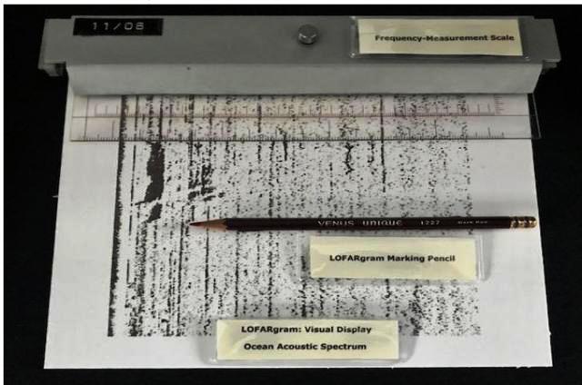
JEZEBELJEZEBEL is a passive sonobuoy system which was used for area searches and localization only so far as the 16 sonobuoy channels of the SSQ-2B system would provide. JEZEBEL processes sound information by analyzing the sounds in the sea into their frequency components and displaying the information on a continuously moving graph in a frequency vs. time format. Each type of surface ship and submarine has a unique frequency "fingerprint" that allowed the JEZEBEL operator to identify the type and the nationality of the target. The technical term for JEZEBEL was "LOw Frequency Analysis and Recording" or LOFARgram Once a submarine was detected with JEZEBEL, then JULIE was used to help refine the position. . Incidentally, a 15-buoy JULIE circle was nicknamed "the Cadillac pattern" as one could allegedly buy a car for the price of the buoys.
The AQA-3, AQA-4 and AQA-5 were the recorders used for JEZEBEL. The AQA-3 used four 3", side-by-side, printouts of continuous input - frequency on the X axis and time on the Y axis. The only difference between the -3 and -4 was an additional knob on the AQA-4 for a 'relate' function. The Jezebel system required an acoustic processor and a display device The AQA's acted borh as an acoustic processor and display device.
JULIE
JULIE was an active sonobuoy system which used the technique called Explosive Echo Ranging (EER). After the sonobuoys were deployed, the aircraft would then drop a small explosive charge into the water known as a Practice Depth Charge (PDC). When it exploded, the percussion wave would bounce off the submarine and the operator would listen for the resultant echo. The system used a paper tape printing recorder and 'Julie rulers' which were calibrated for distance based on ocean temperature.
|
| Julie ruler set for AN/AJH-501. Download image to enlarge. (Photo by Tim Cathcart) |
The disadvantage of JULIE is that the PDC detonations announce to the submarine that it is about to be attacked. Naturally, the submarine executes the maximum evasive manoeuvres (dispense decoys, change depth, turn and take advantage of oceanographic features that would minimize JULIE detection ranges). A well worked up crew (JULIE demanded the highest degree of crew coordination) could attack an evasive submarine before it could exit the JULIE sonobuoy containment pattern. If the submarine increased speed, it generated more noise and increased JEZEBEL detection ranges.By the way, two buoys (SSQ-2B Mod 9) bombed with PDCs would give an ambiguous fix (the arcs would intersect on both sides of the baseline), so a third buoy would be needed to 'resolve the ambiguity' or, alternatively, carry out a MAD sweep across both fixes to see which one was the correct one.
A regular passive sonobuoy could be used for JULIE but it was more expensive to do so. Initially, only one type of sonobuoy was used for JULIE and JEZEBEL but later there were 'dedicated' buoys for each system. The dedicated JULIE sonobuoy was less sophisticated and cheaper because all that was needed was a sensor to detect the PDC "white noise" detonation and the returning echo. Whereas the JEZEBEL sonobuoys were more sophisticated because they were frequency sensitive. There were other design techniques inherent in a JEZEBEL buoy which were used to dampen the ambient sea noise (rain, wave motion, sea life, flow noise around the hydrophone, etc). Later on, a more sophisticated "DIrectional Frequency Analysis and Recording" or DIFAR sonobuoy also provided direction to the frequency source. JULIE was the only EER system. It was supplanted by active sonobuoys that generated their own "ping" similar to a ship's sonar, negating the requirement to drop PDCs.
After the initial detection a submarine was a localized by refining the datum down to attack criteria. In broad terms, one could look at the detection system as getting more accurate when going from SOSUS (note 2) to JEZEBEL to JULIE to MAD. Getting from JEZEBEL to JULIE often required a visual or radar contact though, especially on a snorkelling submarine.
Generally, an acoustic operator was trained to operate both JULIE and JEZEBEL systems. But most crews operated JEZEBEL and JULIE simultaneously thus requiring two operators. In the Argus era, the usual tactical sequence was to detect the submarine initially on JEZEBEL and determine a "rough" fix on its position; then JULIE was used to refine the submarine's position to sufficient accuracy to conduct a multiple torpedo attack. MAD was used during the attack run to confirm the accuracy of the JULIE datum on which the attack was made. Meanwhile the JEZEBEL operator continued to track the submarine, providing indications that the submarine had turned or changed depth.
MAGNETIC ANOMALY DETECTION (MAD)
When flying a MAD pattern manually, it resembled a cloverleaf and the aircraft was flown at an altitude of 300 feet ASL. The Argus also had a more advanced compensation system for the AN/ASQ-10 MAD gear, however all crews hated the magnetic compensator calibration flights. Pilots would fly on the cardinal headings doing either yaws, rolls or pitches in a sinuous fashion. They did their best to minimize aircraft movement in the other two planes, while the MAD operator adjusted the knobs on the compensator box. In its advanced years of service , the Argus was fitted with an automated compensator that supposedly could accomplish the same thing with half a dozen or so movements on each run as opposed the many small steps it took to do it manually.
AN/ASR-3 EXHAUST TRAIL INDICATOR
By 1978, the Exhaust Trail Indicator (ETI) had been removed from the Argus. When in use, the aircraft would fly a designated pattern and the operator would yell out something like sniff on and sniff off when the operator saw an indication on his monitor. As to why it was removed , someone once said that the world is too polluted for it to detect exhaust gas accurately. The ETI black box' was located inside the cockpit just above the pitot tube
Ian Snow, a former Argus crew member, provides more details about the ASR-3. "It was part of the nose lookout preflight check to make sure there was water in a plastic bottle stored next to the ETI box. There was a reservoir in the sensor box. As air flowed through the device, it was humidified and passed through a chamber with a light sensor. Moisture would adhere to the submarine's exhaust particles changing the opaqueness of the light in the chamber. The result was a trace on the Julie recorder that would spike as the aircraft passed through an exhaust trail left by the submarine.
The tactic was to fly successive legs across the wind looking for a peak. If one was detected, the pilot then flew an approach of successively shorter legs proceeding upwind (overall triangular pattern) until the sub's snorkel was sighted . It was good theory but the problem was that you had to be VERY low above the water. Needless to say, not a very safe tactic in the days of advanced LOFAR capabilities. The pilots considered it dangerous at the best of times".
B6 DRIFT METER
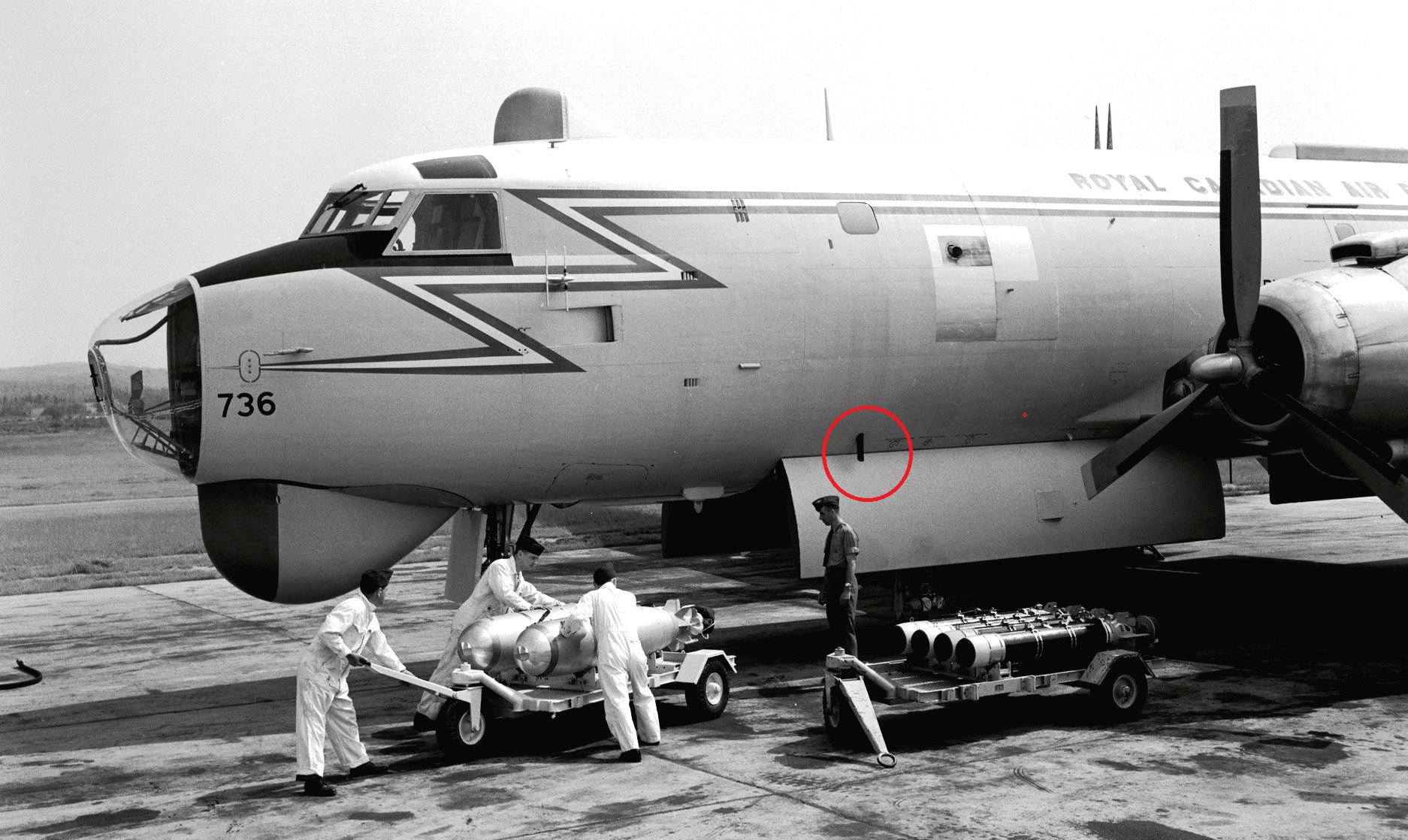 |
| The B-6 Drift Meter was like a periscope. When
looking down through the B-6, the navigator saw a lighted reticule, a rectangle
with a few parallel lines running from one short side to the others. The
lines were to be lined up with the waves on the surface of the water thus
giving an indication of wind drift.
By the 1970s, due to the plethora of navigational devices on the Argus, the B-6 Drift Meter was seldom relied upon to provide drift information. Argus aircraft, serving as gate guardians (those Argus on permanent display) had the B-6 removed and the hole was likely patched over. In this photo, bombs and torpedoes are being loaded aboard an Argus at Greenwood NS. (Photo by Mike Kaehler, CF Photo Unit) |
SCUTTLING OF SONOBUOYS
What happens to a sonobuoy after it has reechoed the end of its useful life? Chat GPT offers this explanation."In general, The specific mechanism for scuttling a sonobuoy can vary depending on the manufacturer and the specific model. However, here is a general overview of how sonobuoys are typically scuttled:
Timer Mechanism: Many sonobuoys are equipped with a timer mechanism that can be set by the operator before deployment. This timer is designed to activate after a predetermined period, usually several hours or days. When the timer reaches zero, it triggers the scuttling process.
Explosive Charges: Sonobuoys are equipped with small explosive charges that are designed to rupture the buoy's casing and cause it to sink rapidly. These charges are activated when the timer reaches zero or when a specific condition is met, such as the depletion of battery power.
Buoyancy Control: Some sonobuoys have a buoyancy control system that can be used to flood the buoy's internal compartments with water. This effectively makes the buoy heavy and causes it to sink. This mechanism can be remotely controlled by the operator or triggered automatically after a set time.
Environmental Degradation: In some cases, sonobuoys are designed to deteriorate over time when exposed to seawater. This can be achieved through the use of materials that break down or dissolve in saltwater. Eventually, the buoy will become too waterlogged to remain afloat and will sink.
Remote Trigger: In addition to timer-based scuttling, some sonobuoys can be remotely scuttled by the operator through a wireless communication link. This allows for precise control over the disposal of the buoy.
It's important to note that the specific scuttling mechanism and procedures may vary from one sonobuoy model to another, and they are typically classified information. This is done to ensure that sonobuoys cannot be easily intercepted or tampered with by unauthorized parties. The scuttling of sonobuoys is a crucial part of their design to prevent them from becoming marine debris and to protect sensitive equipment and data they may contain".
BATHYTHERMOGRAPH TYPES
There are three types of bathy sensors:
Air dropped. The AN/SSQ-36 is an example.
Ship deployed. The sensor is 1.5 inches in diameter and around a foot long. It fits into a launcher located aft on the ship's quarterdeck. The launcher was a steel post perhaps 4 ft high with a tube mounted on its top and pointed downward about 45 degrees The probe could bc released from the Ops room. However, BTs need to impact the water vertically to depress the baseplate thus releasing the sensor device and the rotochute/parachute.
An XBT (disposable) is released at depth by a submarine. It floats to the surface and then it sinks. It's released through a pressure hull penetrating device, same concept as a torpedo tube. Ship and sub bathy probes are connected by disposable wire to the recorder.At the start of a search,, an AN/SSQ-536 XBT bathythermograph was launched in order to give the crew some idea of the water temperature. The key word in looking at the BT graph was thermocline. The BT was dropped to determine the temperature of the water by depth and in particular to determine the location of the thermocline. The thermocline had a major impact on the transmission of sound in the ocean. If the hydrophone was on one side of the thermocline and the sub on the other, the operator was not likely to hear it.
Along with the temperature of the water the depth of the water also plays a role. The speed of sound underwater increases with greater depth due to the increased pressure, which causes sound waves to bend away from the area of higher sound speed. As the sound goes deeper it bends back up to the surface. The sound could reach the surface over 20 nautical miles from the vessel creating what is known as a convergence zone. This phenomenon repeats itself until the sound dissipates due to attenuation.
LOFAR, used in this document, is an acronym for Low Frequency Analysis and Recording.It is defined as a search technique using omnidirectional sonobuoys. The output from the AN/AQA was recorded on paper and it was called a LOFARgram As originally implemented, the Argus used omnidirectional sonobuoys. As sonobuoys evolved, DND included DIFAR (Directional Frequency Analysis and Recording sonobuoys) and VLAD (Vertical Line Array DIFAR) sonobuoys. Crews also trained on Active sonobuoys but they were seldom used so as not to alert the submarine that they were being listened to from above. There are more modern sonobuoys available than those that were used in the 1980s.
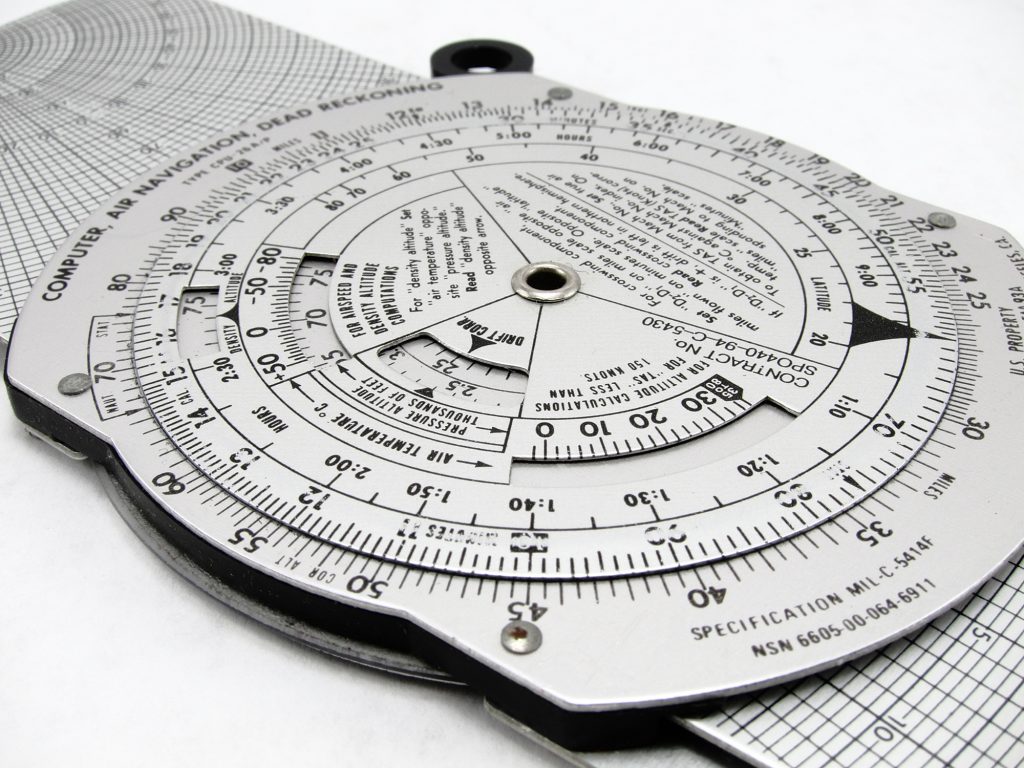 |
E6B. This is a Dead Reckoning, Air, Navigation Computer.in the form of a circular slide rule. It is one of the very few analog calculating devices in widespread use in the 21st century. It comes in a metal version and Jeppenson also produced a variant in a plastic version .The E6B could make simultaneous calculations on such things as air speed, time to travel, air density etc. All civilian pilots had them before the digital calculator became the norm. Click on image to enlarge. |
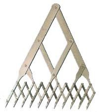 |
10 Point Dividers. They were used to measure the lines produced on the Jez gram by the AQA-5 recorders.. |
 |
AQA-5 Output . The AQA-5 produced this type of output. With two AQA's aboard the Argus, it was possible yo monitor the output of 8 sonobuoys. A 2HB pencil was used to mark up the output Click on image to enlarge. |
 |
LOFARgram Example (Low Frequency Analysis
and Recording). Click on image to enlarge. To be able to read it , it took
quite a number of classes during training.
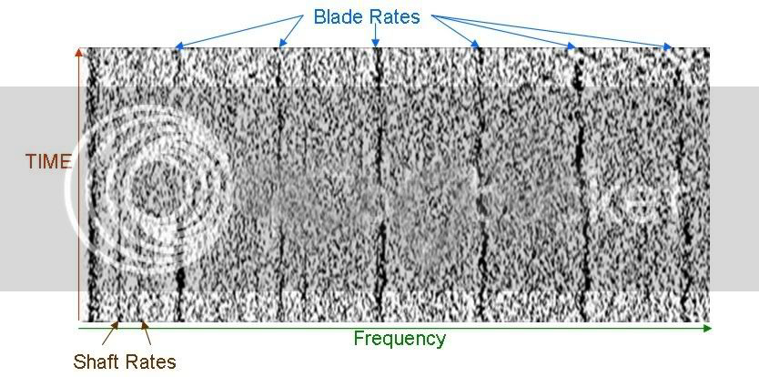
The trace is indicating a surface ship. With 10 point dividers it would be possible to say that the detected vessel likely has 4 blades on the prop and the RPMs of the prop. The surface ship was likely passing a sonobuoy around the 65 minute mark. There is more information that you can get on the LOFARgrsm such as speed and depth. That is the part of the AQA-5 that was covered up when persons without the proper security clearance were on board. During a static display of the Argus at an air show would be one reason for covering up things. |
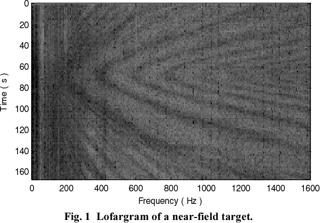 |
LOFARgram example of a near field target. Click on image to enlarge. A near-field target is an object or target that is in close proximity to the radar or sonar operator. |
FOOTNOTES
1) 1,800 feet was the distance used by the Royal Canadian Navy. IN contrast, 1,000 yards is the figure quoted from 'The Naval Institute Guide to World Naval Weapons Systems", 1991/92 by Norman Friedman..2) The first SOSUS signal of a Soviet diesel submarine was detected by the Cape Hatteras Naval Facility (NAVFAC) on June 26, 1962.
Credits and References: 1) Ian Snow RCAF/CF retired.<va3qt-4(at)sympatico.ca>
2) CU-351 http://www.dscc.dla.mil/Programs/MilSpec/ListDocs.asp?BasicDoc=MIL-C-18277
3) Greenwood Military Aviation Museum http://www.gmam.ca/argus.htm
4) APN-20 Control Box http://www.bpbsurplus.com/lc/cart.php?target=product&product_id=17878
5) APN-20E http://www.tpub.com/content/radar/TM-11-487C-1/TM-11-487C-10854.htm
6) http://www.designation-systems.net/usmilav/jetds/an-apn.html
7) Doppler http://www.flightglobal.com/pdfarchive/view/1958/1958-1-%20-%200908.html
8) IFF http://www.tpub.com/content/MIL-SPEC/MIL-R/MIL-R-5532E/index.htm
9) http://en.wikipedia.org/wiki/Canadair_CL-28
10) APN-70 http://www.loran-history.info/downloads/Jansky%20_%20Bailey%201962.pdf
11) Mark 1 vs Mk 2 http://www.airforce.forces.gc.ca/site/equip/historical/arguslst_e.asp
12) APA-74 photo http://www.smecc.org/
13) ARA-8 photo Tailwheel.NL http://www.tailwheel.nl/downloads/p47trainingmanualsmall.pdf
14) http://www.springerlink.com/content/u743470l0542w510/ . Woods Hole # 4692.
15)http://www.airforce.forces.gc.ca/12w-12e/sqns-escs/page-eng.asp?id=472
16) http://www.designation-systems.net/usmilav/jetds/an-aq.html
17) http://www.ww2aircraft.net/forum/modern/legend-julie-jezebel-1413.html
18) Julie-Jezebel http://www.gwu.edu/~nsarchiv/NSAEBB/NSAEBB75/
19) BC-733 http://www.gordon.army.mil/ocos/Museum/bc3.asp
20) Bill Griffith VE3WGX <ve3wgx2(at)sympatico.ca>
21) Bert Campbell <navigator1(at)eastlink.ca> 5,000 Argus Hours - Radio Officer/Navigator
22) Olive Drab Electronics Gibson Girl http://www.olive-drab.com/od_electronics_scr578.php
23) Bryan Nelson, Greenwood Military Aviation Museum. <gmam001(at)hotmail.com>
24) ASQ-8 http://www.tpub.com/content/radar/TM-11-487C-1/TM-11-487C-10951.htm
25) John Mackesy VK3XAO <mack(at)melbpc.org.au>
26) P.G.M. Truren <.g.m.truren(at)planet.nl>
27) Ernest Cable - Associate Air Force Historian and Shearwater Aviation Museum Historian <erncar(at)ns.sympatico.ca>
28) David C. Fletcher <dcf(at)mars.ark.com>
29) The Evolutionary Development of the Patrol Aircraft in the United States Navy By M.A. Joenks. Master of Arts in Diplomacy and ilitary Studies. http://www.hpu.edu/CHSS/History/GraduateDegree/MADMSTheses/files/2008MichaelJoenks.pdf
30) AN/UGC-503 modem photo by Matt <rokknrol@gmail.com>
31) Tim Cathcart <Tim.Cathcart(at)snclavalin.com>
32) First SOSUS Signal at Cape Hatteras https://www.navalhistory.org/2018/06/22/first-sosus-signal-at-cape-hatteras-june-1962
33) Rick Bialachowski; former Argus crew