 |
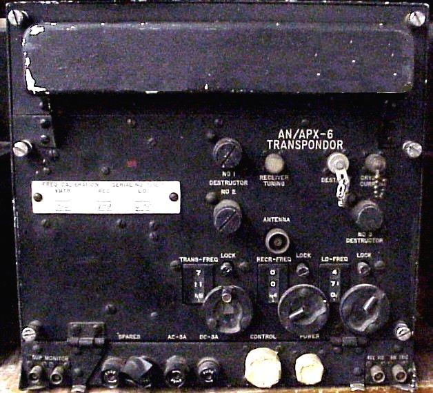
| AN/APX-6 unit (Courtesy Fair Radio, Lima Ohio) |
The original APX-6 was introduced around 1950, supporting only single pulses as a reply for a mode 1, 2 or 3 challenge In 1952, a modification to the original RT82/APX-6 was available, which added a plug on the front panel mid-left. This plug connected to a coder unit KY95/APX which replied with 5 or 6 bits on each challenge.Two supplementary purposes of the APX-6 are:
a) Two provide two separate channels for the identification of specific friendly airplanes among many friendly planes and
b) to provide means for transmitting a special reply referred to as "emergency".Dave Trojan adds this this information about the APX-6 in US service. "The unit was classified at the time (at least during the early 1950s) and required special handling. Early frequencies used in these sets were also classified and the radio operator or pilot had to remove the entire set and carry it with him if no military guard facilities were available. Codes had to be set before flight and were not changeable during flight. One of the most interesting things about the APX-6 transponder unit is that they contained explosives for destruction of the tuning heads (the cavitrons) if the unit was about to fall into enemy hands. There were three Cartridge Activated Devices (CADs) in front of each of the three cavities controlled by a battery bus. The pilot could initiate detonation if the situation arose using a guarded switch on the IFF panel to manually activate them. The flight manual states that if the APX-6 transponder is destroyed during flight it should be reported immediately after landing. So destruction must not have been particularly hazardous to the pilot and must not have affected any control systems to prevent a normal landing after a manual destruction.
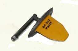
There was also an impact switch to automatically actuate the destructors upon a crash landing. The unit contained three detonators that were inserted into the face of the unit and they worked like a type of shotgun shell, but they were more like the size of a .45 round to self destruct the tuning heads. The idea was to keep the bad guys from determining the operating frequency, which, at that time, was changed every day. Later on, after an intact unit was compromised, the Selective Identification Feature (SIF) coder was added to the system and the frequencies were fixed at 1030 and 1090 MHz. Mode 4 IFF came much later. The voltage required to set off the explosives was less than 1 volt. Ground technicians always kept a wary eye on the live rounds when working around the units and there are stories of them accidentally setting them off during maintenance which required the replacement of the entire unit".
|
| AN/APX-6 unit (Courtesy Fair Radio, Lima Ohio) |
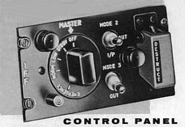
C544 /APX6 control panel (Courtesy Google books)
 111 111 |
 |
| AS-133APX | AT-234/APX |
| Both of these are the standard APX-6 antennas but the Canadian Avenger does not appear to be fitted with either. | |
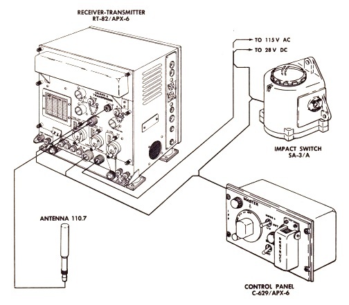 |
| AN/APX-6 interconnection diagram. Of interest is the Impact Switch. The impact switch was mechanically or electrically triggered by sudden deceleration or force. When activated, it either disconnected power to the set, preventing further operation, and/or activated a small thermite or squib charge to physically burn the code oscillator crystal(s) or destroying the coding components so they couldn't be recovered. |
Back To Avenger Electronics
Credits and References:1) AT-234 antenna Columbia Electronics http://www.columbiaelectronics.com/id239.htm
2) APX-6 http://www.tpub.com/content/radar/TM-11-487C-1/TM-11-487C-10916.htm
3) AS-133 antenna. Vintage Avionics http://members.home.nl/a.k.bouwknegt/index_bestanden/ARN21diagrams.htm
Aug 13/25