AVENGER ELECTRONICS
If equipment configuration records existed for each Avenger
variant that's exactly how they would they would be listed. Since
these lists are not available, the Avenger's electronics have been arranged
into three broad categories. These are: tactical, communications and
navigation. "Textbooks" were prepared by the School of Naval Aircraft Maintenance
(SNAM) but the MICN from which some of the low res photos are derived
is silent on the electronics details. American manuals were used as a baseline
and any differences in the Canadian Avengers were explained in training/reference
manuals produced by SNAM.
The list below shows all the equipment that was ever fitted
on all variants of the Avenger even it was only experimental. Many of these
equipment designators were recorded from display boards which accompanied
newly converted Avengers in photos which appear in the previous document
. These photos are captioned mock-up of AS 3M (above) and first prototype
AS 3 Mk 2 (below). Every effort has been made to ensure the highest
accuracy. If there are errors or omissions, please contact :jerry.proc@sympatico.ca
William Nye published data sheets for the Avenger TBM-3 in the August
and September 1962 issues of the magazine Model Airplane News. .
It is believed that most of the equipments listed in his sheets and reproduced
immediately below were carried in the RCN AS 3 Mk 1s. There were two minor
errors in the original list which have been corrected.
Radio communication equipment
AN/ART-13 transmitter
ARB receiver and ARC-5 series equipment
AN/ARC-1 VHF transceiver
Radio navigation equipment
AN/ARR-2 VHF homing receiver
AN/APN-1 radio altimeter
Tactical Equipment
Search radar AN/APS-4
IFF
AN/APX-2 IFF
ELECTRONICS MANIFEST
| TACTICAL |
| AN/APS-20A |
Search radar. Used in Avenger type TBM-3W2 only. S-Band
(2880 MHz +/-30 MHz) search radar. Manufactured by Hazeltine and General
Electric. 1 Megawatt power output for A and C models. 80 -100 mile
range. For the E version it was 2 megawatts (pulse peak). Range up to 200
nm for the E version. It is not confirmed at this time if the TBM-3W2 carried
the 'A' variant but it's fairly likely. The pictorial indicates all the
components of the APS-20 system, however not all of them would have been
used in the Avenger. This radar could detect a snorkel at 20 miles in a
low sea state.
APS-20 system components
(Courtesy T-pub.com)
APS Antenna control components.
(Courtesy
Tpub.com)
APS-20 antenna control (Courtesy
Bpbsurplus.com)
Actual APS-20 components |
| AN/APS-4 |
ASH (Air-Surface Homing) radar. Used on AS-3 Mark 1. The
APS-4 was a light-weight, pod-mounted airborne search radar which was suitable
for either Airborne Interception (AI) or Air-to-Surface-Vessel (ASV) applications
in the X band. On the Avenger, this equipment was carried under the
starboard wing and had the same form factor as a 500-lb bomb. The
complete system weighed 180 pounds.
The radar dish can be moved 75 degrees on either side of centre for
air intercept applications and 30 degrees above and below centre for surface
search of vessels or aircraft attacking from above. The frequency
used was 9375 +/-55 MHz. Pulse repetition frequency adjustable for either
600 or 1000 cps. The peak RF output power was 35 kw. Made by Western
Electric. |
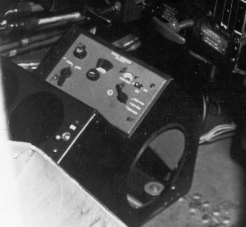
| AN/APS-501 |
Installed in AS 3 Mk 2 for testing. It did not become operational.
APS-501 system components. (See
individual photo credits)
APS-501 scope and control box. (From
publication - Operating Instructions for R.C.N. A/S-3 and A/S-3M Aircraft.
MICN. 3.10.11A , courtesy Leo Pettipas) |
| AN/UPD-501 |
Used on Mks AS3 Mk 1, AS 3M. and
AS 3M2. SHF Direction finding set. On the Avenger, there were two configurations.
Single antenna on the AS3 Mk1 and dual antenna on the AS 3M. The
dual antenna configuration covered the X and S radar bands. See Featured
Equipment section. |
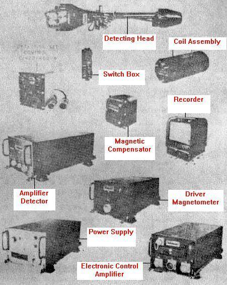
| AN/ASQ-8 |
Used on AS-3M and AS 3M2. Magnetic
Anomaly Detector. Detection range was 500 yards. [See footnote 3] . This
ASW equipment was fitted in the Observer's Mate's position of an Avenger
AS-3M. The MAD recorder is in the upper right section of the compartment.
MAD boom could be extended 5 metres beyond the tailplane.
ASQ-8 system components(Courtesy
Tpub.com) |
| AN/SSQ-2 |
Sonobuoys. Sixteen sonobuoys were carried in the Avenger.
SSQ-2 overview . (Courtesy HNSA) |
| AN/ARR-3 |
Sonobuoy receiver. A single conversion
FM superhet receiver covering 60 - 75 MHz. The unit itself is powered from
an external dynamotor power supply whose input is 24 VDC. The ARR-3's were
in the operational AS 3 Mk 1's.
AN/ARR-3 components.
(Courtesy
www.history.navy.mil) |
| AN/ARR-26 |
Installed in AS3 Mk2. Sonobuoy/Bathythermograph Receiver;
manufactured by Texas Instruments. The ARR-26's were fitted in the AS 3M's. |
| AN/APX-2 |
IFF Mark III airborne combination Interrogator-Responsor-Transpondor
manufactured by Stewart-Warner and Bendix. Reliable maximum range for transponders
is 90 miles; for interrogators and responsors, 60 miles. Minimum range
is 2 miles. The APX-2 was replaced by the APX-6 in the AS 3Mk2. The two
antennae for the APX-2 are located on the forward and middle of the starboard
bomb bay door. |
AN/APX-6
(RT82) |
Installed in AS3 Mk2. Mark V, 'L' band IFF transponder
made by Packard-Bell, Hazeltine and Stewart-Warner Corp. Operates
at 960 and 1150 MHz. 1 Kw output. Maximum range is 150 nm.
AN/APX-6 components. |
| AN/ART-26/T-179 |
Radio Transmitting Set AN/ART-26 is intended for airborne
use as part of an AEW (Airborne Early Warning) system. It is designed
to relay the radar video, together with the synchronizing signals to the
surface control station or airborne control station for presentation on
the control station indicator. The AEW range is therefore the range of
the APS-20 itself. Uses antenna AS-366/AR. Power Output: 15w nominal; Frequency:
465 to 515 MHz. Modulation: AM. 115 vac, 400 to 2, 600 cps, 1 phase, 3.2
amp
AN/ART26 and rectifier unit. (Courtesy
Tpub.com)
AN/ART-26 actual photos (Courtesy
Marty Reynolds) |
| AN/ART-28 |
Radar Relay Transmitter for use with AN/APS-20 and radio
receiving set ARR-27. It was evaluated against the ART-26 by VX-10 Squadron.
Weight: 73.5 lbs
Mode: Coded Pulse-Modulated Carrier, PRF: 300
Frequency Range: 460-510 MHz
Power Input: 115 VAC 320-1000 Hz 3-phase 2.5 A and 28 VDC 5.6 A, 8.5
A Peak
Power Output: 400W PEP
Number of Channels: 464.87, 477.43, 490.00 and 502.56 MHz
Part of: ART-28
Description: Radio Transmitting Set ART-28 is primarily designed to
relay radar information from an aircraft early warning radar set to the
receiving and indicating equipment in a surface control station. The application
of this equipment permits the plan position indicator presentation, obtained
by radar scanning from the aircraft at high altitude, to be reproduced
in the surface control station. The relay transmitter is installed in the
aircraft to operate directly from the output signals of the aircraft early
warning synchronizer. However, the transmitter also may be installed in
an intermediate aircraft to re-relay the radar signals picked up by a relay
receiver from another aircraft early warning relay transmitter. This equipment
is used with airborne early warning units, such as Radar Set APS-20. Made
by Westinghouse Electric Corp. It is not clear if this was just an evaluation
unit or not. |
| Model unknown |
Tape recorder. Used for "proof of detection and kill" when
used in conjunction with the sonobuoy receiver. |
|
COMMUNICATIONS
|
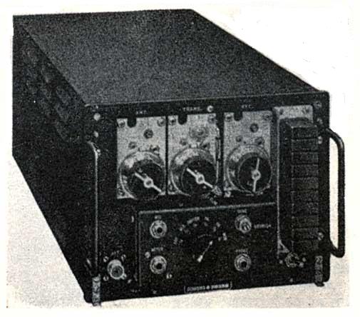
| AN/ART-13 |
Collins autotune HF transmitter.
Frequency range 1.5-18 MHz and 200 to 600 KHz if the low frequency oscillator
is installed in the transmitter. Modes: CW/ MCW and AM It has ten autotuned
preset channels Power output is approximately 100 watts. Used for Liason
communications. The transmitter shown has the LF/MF optional oscillator
installed.
Transmitter only (Photo courtesy
Collins Club web page) |
| AN/ARC-5 series |
Typically used as a command set between aircraft. The specific
receiver/transmitter pair is not known at this time. Illustrated is typical
ARC-5 transmitting equipment. 24 watts output.
Transmitter only.
(Photo by Dave Hollander) |
| BC-453/R23 |
LF receiver. Part of ARC5 series
radio equipment. 190-550 kHz.
Receiver only (Photo by Jerry
Proc) |
| ARB-4 |
HF receiver- 6 tubes. Companion receiver to the ART-13
transmitter in the Avenger. It covered the frequency range 195 KHz to 9050
KHz in four bands. Modes: CW-MCW-Voice. Power input 28VDC @ 4 amps. Made
by RCA. The front panel controls are minimal, as it was intended to be
used as a remotely controlled receiver, from a Pilot's or Navigator's control
box. The Band change switch is motorized; frequency tuning is by flexible
Bowden cable and the bandwidth/antenna selection is by relay. Used for
Liason communications.
Receiver only (Photo from RCN
manual) |
| AN/ARC-1 |
VHF transmitter-receiver - 9 channels (xmit/rcv),
one guard channel, all crystal controlled. Frequency range 100-156 MHz.
Modes: AM only. Transmitter output is 8 watts. The ARC-1 antenna also doubled
as the support for the forward end of the wire antenna.
Replies from the Navairgen mail list, all from former Observers'
Mates, support the belief that only the pilot and the Observer used the
VHF/UHF radios.
RT-18/ARC-1 Transceiver (Photo courtesy
Surplus Conversion Handbook)
ARC-1 Control Unit (Courtesy
Google Books)
Antenna Mast Detail ( DND
photo via Leo Pettipas) |
| AN/ARC-9/RTA-1B |
Some aircraft had the ARC-9 in lieu
of the ART-13 but retained the companion ARB receiver. Frequency coverage:
2.5 13.00 mc.; crystal controlled; 50 watts. Modes: AM-CW. Circa 1943.
Photo of unit. (Courtesy: Radiomilitari.com) |
| AN/ARC-27 |
Fitted on AS 3M and AS3 M2. This set was fitted into the
Avenger in order to give it UHF capability. RT-178/ARC-27 UHF aircraft
receiver-transmitter. Frequency Range 225-399.9 MHz; Modes: MCW/Phone;
Power output: 9 watts; 18 preset frequencies on any one of 1750 frequency
channels. Transmitter may be tone modulated at 1020 Hz for emergency or
direction finding purposes. One guard channel in the 238- 249 MHz range
can be simultaneously monitored.
Replies from the Navairgen mail list, all from former Observers'
Mates, support the belief that only the pilot and the Observer used the
VHF/UHF radios.
ARC-27 unit- exterior (Photo courtesy:
www.Radiosamling.dk)
ARC-27 unit - interior (Courtesy
Fair Radio Sales)
ARC-27 stub antenna (DND photo
from the collection of Leo Pettipas) |
| AN/ARC-34 |
Not sure which variant had this radio.
Perhaps it replaced the ARC-27 set. UHF radio; 225-399 MHz frequency
range; 1750 channel selection spaced 100 KHz apart, 20 preset channels.
Output: 10 watts. Modes: MCW and Phone |
| CAM-1 |
Inter Communication Amplifier. Used
on all variants. It provided a method of communication between members
of the crew. The CAM-1 was designed for use with both carbon and dynamic
microphones, but the microphones in all stations had to be of the
same type. Microphone "type" was switch selectable. Power input 28
VDC @ 1.1 amps. Official documentation indicates that the original
interphone gear was replaced with the CAM-1 interphone amplifier as part
of the RCN's Avenger conversion program. |
| AN/AIC-501(?) |
Radio control (?) Requires verification |
|
|
| NAVIGATION |
| ADF-14 |
Radio compass. (ADF) 190 KHz to 1725
KHz. or 200 KHZ to 1750 KHz. Made by Lear. Also see ADF featured equipment.
ADF-14 system. (Photos by Charles
Darby) |
| CMA-301 |
Canadian Marconi Radio compass. Evaluated for use on the
Avenger but not accepted. It was designed to meet Canadian Department
of Transport requirements and ARINC standards and weighs 30 lbs. The flat,
ferrite-core aerial can be suppressed below the aircraft skin. The sense
aerial is specially designed to meet high-speed aircraft requirements and
has a special coupling unit to reduce cable capacitance and increase signal/noise
ratio. Accurate tuning and good frequency stability are provided by a precision
electrical servo tuning system and temperature compensating components.
The loop can rotate through 175 deg in approximately four seconds. Also
see ADF featured equipment.
Control Unit only.(Courtesy Flight
Magazine) |
| AN/ARN-6 |
One reference which was found, suggests that the AN/ARN6 radio compass
was installed but it doesn't explain as to how many aircraft had it or
when it was changed to the AN/ARD-7. Perhaps it was experimental. |
| AN/ARD-7 |
Radio compass (ADF). 190 KHz to 1750
KHz. A standard AN/ARD-7 configuration consists of a corrector, AT-593/ARN-42
loop antenna, R-637/ARN-41 receiver, AM-1208/ARN-42 control amplifier
and ID-9/ARN-6 indicator. Power input 28 VDC @ 3 amps. This is the military
version of the Lear ADF-14. Also see ADF featured equipment.
AN/ARD-7 system components
(PDF courtesy Robert Downs, WA5CAB ) |
| AN/APN-1 |
Radar altimeter. 420-460 MHz; Uses Doppler
frequency shift; Ranges: 0-400 and 0-4000 feet. Circa 1943.
APN-1 Control Unit only. (Photo
courtesy Kurrajong Radio Museum) |
| AN/ARN-21 |
TACAN. Tested in AS2 Mk2 but it never
become operational.
Cockpit instruments.(Courtesy Vintage
Avionics) |
| AN/ARR-2 |
VHF homing receiver. The AN/ARR-2
is the combined version of the AN/ARR-1 (also called the ZB-3) and the
BC-946 command set. The ARR-1 was a small TRF set covering 234-258 MHz,
using acorn tubes whose , output was 800-1000 KHz. This set then connected
to the BC-946 which took the signal and demodulated it to recover a Morse
signal. The ARR-2 was a combination of these, in a Command set sized box,
which tuned fixed channels, and used miniature tubes in the front end.
The ARR-2 ZB antenna was mounted on the aft end of the starboard bomb bay
in the early Avenger Marks. On the later AS 3 Mk 1s, the AS 3Ms and the
AS 3M2s it was relocated to the starboard side in front of the pilot.
ARR-2 trio . (Photo via Wikipedia) |
|
OTHER
|
| Rod
Antennas |
There was an array of rod antennae
affixed to the bomb bay doors. When the aircraft was on the ground
and with the doors open, it was squadron custom to unscrew any rod antennae
to avoid their being broken off or bent by ground handling equipment or
by chock pullers who were in the habit of rolling under the aircraft rather
than walking around the propeller. Most rod antennae were made out of welding
rods painted yellow, which were much more durable than the real thing.
They would bend easily without cracking at the bases and could be straightened
many times without breaking. Three antennae were mounted on the starboard
bombay door and one on the port door. It is believed that two of the antennas
were used with the ARR-26 sonobuoy receivers, and one with the ARR-3. The
assignment of the fourth antenna is not known at this time. Depending on
the variant, the position and quantity of rod antennas may vary slightly.
(Norman
Fitzmaurice DND/PAC/PA-136549) |
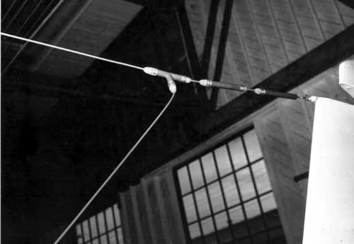
| Feed
Line |
This photo illustrates the antenna feed line
for the wire antenna. Because it bonds with the horizontal wire, the Avenger's
wire antenna is actually 'T' shaped and the entire unit is the radiator.
With radiation resistance typically below 10 ohms, there are some heating
losses due to the high currents in the antenna itself and the counterpoise
(ie the fuselage). That's one reason why trailing wire antennas were
installed on larger aircraft. It does not make any difference if
the feed point forms a symmetrical 'T' versus an asymmetrical 'T',
at least not from the standpoint of of radiation resistance. (DND
photo) |
| AS 3M Antennas |
This pictorial shows the antenna locations. It is not known what
antenna was used for the ADF sense antenna. (From the book "The
Canadian Avenger in the RCN. Modified by Jerry Proc) |
| TBM-3W2
Antennas |
Because the role of the TBM-3W2 was different from that of the AS 3M,
its electronics fit was therefore different. Since this variant did
not carry sonobuoys, all the sonobuoy antennas can be discounted. It is
assumed that the ART-13/ARB-4 combo was used for HF communications. The
fitting of UHF comm is unknown at this time. (Graphic by Leo Pettipas;
modified by Jerry Proc) |
| G4B |
Pilots gyro compass. |
| Searchlight |
American Avengers were fitted with the L11 searchlight whose form factor
was bigger than the APS-4 radar. In Canadian service, the Avenger did not
use the searchlight. Instead, it was the tactic called "Glow-worm." It
was a hair-raising, three part night time manoeuvre - a dive to increase
the airspeed followed by a sharp pull-up in order to loft rocket flares
high into the night sky and a quick pushover in order to visually attack
the submarine illuminated by the flares. Glow-worm rockets could be fired
individually or as a salvo of four. This was switch selectable from the
cockpit. |
FEATURED EQUIPMENT
RADIO COMPASS (ADF)
In 1954, the Lear Radio ADF-14, and the Canadian Marconi
CMA-301 were being evaluated for use in the Avenger based on the current
information at hand. It would appear that the Lear device was adopted as
the Avenger's radio compass but in its military version, the AN/ARD-7 [2]
. There is at least one photo showing the ADF-14 installed in an Avenger
cockpit but no photos of the Marconi CM-301A.
The receiver in the ARD-7 system appears physically identical
to that of the ADF-14. A comparison photo of the ADF-14, ARD-7
and CM301A can be found here.
There is one difference between an ADF-14 and a ARD-7. The ARF-7 should
have name a nameplate affixed to the front panel.
There is a bit of a mystery concerning the corrector
strip. The corrector strip is used to electrically compensate for an
ADF bearing error that is caused by the antenna effect of the aircraft
fuselage. It was part of the ARD-7 and ADF-14 kits but so far there is
no photographic evidence to indicate that it was fitted on the Avenger.
A photo of a Sea Fury fighter bomber also shows a loop antenna without
the corrector strip so its lack of use remains a puzzle.
 |
| The ADF installation on this Sea Fury also lacks the corrector strip.
(From the collection of Leo Pettipas) |
 |
| This illustrates the ADF loop antenna mounting in a test aircraft of
VX-10 squadron. The lack of a corrector, especially during an evaluation,
is a mystery. In service, the loop antenna was mounted directly above the
Observer's Mate in the mid-upper cockpit section. (DND/PAC/PA-136529
from the collection of Leo Pettipas) |
 |
| The "in-service" location of the radio compass loop antenna in the
3M and 3M2 variants. (Graphic via Leo Pettipas) |
 |
| This photo shows the placement of the ADF-14 in the cockpit of an AS3
Mk2 prototype. It is assumed this is the commercial version otherwise the
military version would bear a nameplate with its JETAS registered number
of ARD-7. |
 |
| The radio compass indicator. (Extracts from photo DND/DNS-11279
held by the Shearwater Aviation Museum) |
PILOT'S RADIO CONTROLS
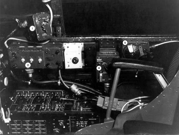 |
| These were the Pilot's radio controls in an operational Canadian Avenger.
The AN/ART-13 transmitter and ARB-4 receiver control boxes have been removed
and likely relocated to the Observers Mates action station. This control
box relocation would have relieved the Pilot of having to operate the ART-13/ARB-4
HF radio combo.
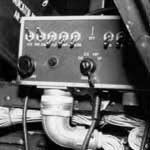
1) AN/ARC-1 VHF control box.
2) C38/ARC-5 control box. It controlled up to four receivers.
The controls for the AN/ARR-2 receiver were to the right of the white dividing
line. The leftmost portion controlled the audio volume up to three other
receivers. This would include an AN/ARC-5 VHF receiver (position
A) , AN/ARC-5 MF or HF receiver (position B) and AN/ARC-5 MF
or HF receiver (position C).
3) This addition in the vacated space is a Canadian modification. It
is believed that a second ARB remote tuner was installed at the OM's
station. If that is true (and it seems logical from a crew ergonomic viewpoint)
it would follow that the unknown panel in question incorporates a switching
function that allows either the pilot or the OM to control the ARB receiver
through their respective ARB remote tuners, but not simultaneously. The
normal switching matrix protocol would be for the last position (pilot
or OM) to depress the button on the unknown panel (there would need to
be a similar panel at the OM's station) to select their ARB remote tuner
to control the receiver.
4) AN/APX-2 IFF controls
5) ARB-4 receiver remote tuner. The ARB remote tuner allows the
pilot to manually tune the ARB MHF radio to a frequency in one of the radio
bands selected on the ARB receiver by the Observer's Mate.
(Photo via Shearwater Museum) |
Ernie Cable, Shearwater Historian, provides this explanation
for the Pilot's radio controls. "The missing Pilot radio control panels
in the AS 3 are for the ART-13 (MHF) transmitter and the ARB (MHF) receiver.
Now the Pilot has no control over these radios, but he can still listen
to the ARB and ARC-5 receivers through the Rec B and Rec C switch
functions on the C38/ARC-5 control panel (The ARC-5 receive frequencies
are the same as the transmit frequencies selected for the ART-13, with
some exceptions.) This tells us that the ART-13 and ARB controls have been
moved to the Observer's Mates stations since he is the one who operated
the HF radios. More importantly, note that an ARB remote tuner still remains
in the Pilot's cockpit; but, for the remote tuner to operate, the proper
frequency band must be selected on the ARB receiver control panel which
is no longer in the Pilot's cockpit. So, the unknown panel with the single
push button in the place of the ART-13 and ARB control panels is "probably"
a "push to control" button for the ARB remote tuner that allows the Pilot
to assume control of the ARB remote tuner from the OM station.
This makes sense in that the wiring for the Pilot's ARB control panel
was already in place from the previous TBM-3 configuration. Under normal
operating procedures in the AS 3, the OM would have control of the ARB
remote tuner.
 |
| In contrast to the previous photo, these are the Pilot's radio controls
in an American Avenger. (Via Google Books) |
RADIO CONTROL PANEL
 |
June, 1953. This is believed to be the
AN/AIC-501 fitted into a test aircraft. Click to enlarge. (From
the collection of Leo Pettipas) |
WIRE ANTENNA DETAILS
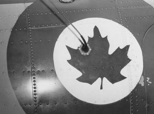 |
| Feed through insulator for wire antenna feed line. (Photo PA-136533
DND/PAC by William Parrell) |
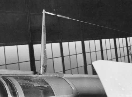 |
| On this AS-3, the forward end of the wire antenna was attached to the
top of the ARC-1 antenna using strain insulator 126-SE-100. (Photo
DND/PAC PA-136533 by William Parrell) |
 |
| Wire antenna, aft end detail. From left to right: Tee splice 126-TS-100,
strain insulator 126-SE-100 and tension unit 126-TU-100. The Tee splice
was usually at the mid point of the span. Shown, is the installation
on a TBM-3W2 (Photo PA-136539, DND/PAC by William Parrell) |
 |
| This was the primary method of securing the wire antenna to the tail
of the aircraft, likely an AS 3 Mk 2 in this example. (Photo PA-136538,
DND/PAC by William Parrell) |
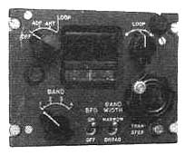
AN/UPD-501 SHF DF RECEIVER
The UPD-501 was a High Probability Radar Early Warning directional finding
receiver which was used to detect radar emissions on the SHF radar bands
and gave some indication of the frequency in use, bearing, and the antenna
rotation period. The receiver was connected to an airborne version of an
horn antenna assembly.
This device was the outcome of a project initiated by Naval Headquarters,
and was a contemporary of the early MAD work. It was a wide-band
dual-band electronic countermeasures (ECM) receiver system. This
project was started in the early 1950s by the National Research Council
who undertook to develop "a simple instantaneous direction-finding receiver-display
for detection of non-co-operative radar transmissions expected to be of
short duration". It was designed to listen for radar emissions from
submarines, surface vessels and even aircraft. The aeronautical version
featured two antennae with feed horns on them, one for X-band and the other
for S-band radars, the expected enemy frequencies. The antennae had
to be in a container of proper aerodynamic design to shield them from the
slipstream. The chosen container turned out to be nothing more than
a common aluminum soup pot. A task for VX 10 was to determine the
feasibility of belly-mounting the unit on the Avenger. Although only
S-band horns were fitted, a preliminary trial showed good results; in fact,
a cross-country flight in early 1954 picked up all the (classified) Pinetree
Line radar sites then in operation.
The original single-can unit was not practicable for housing both S-
and X-band components and switching relays, so a double-can affair, with
one can situated on top of the other, was devised. Two of these two-can
sets would be fitted to each aircraft, and it remained for VX 10 to determine
where on the aircraft they should be mounted. Two options were available:
(1) fore and aft, with one set suspended beneath the engine cowling, the
other on an arm extending rearward from the tail cone; or (2) one set on
either wingtip. The fore-aft configuration was the one chosen for
the Avenger AS 3M operational aircraft, which is curious because it suffered
from shielding by the fuselage and anomalous propagation of signals.
Furthermore, reception in both locations was hampered by lack of directional
accuracy and false echoes from reflections of incoming signals off the
fuselage and other parts of the aircraft. The superior wingtip-mounted
option was not taken for the Avenger. Interestingly enough, this somewhat
problematic fore-aft configuration was also applied to those Air Force
Lancasters that were fitted with AN/UPD-501.
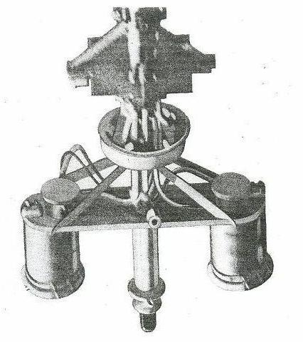 |
| Airborne version of the UPD-501 antenna with radome removed. (Photo
courtesy RCN) |
 |
| December 1953: A closer look at the early UPD-501 "soup pot" antenna
enclosure on the AS3 Mark 1. (Photo by William Parrell DND/PAC/PA-136535) |
 |
| AN/UPD-501 receiver. The system was made by Cossor
Canada Ltd. (Photo by Jerry Proc) |
 |
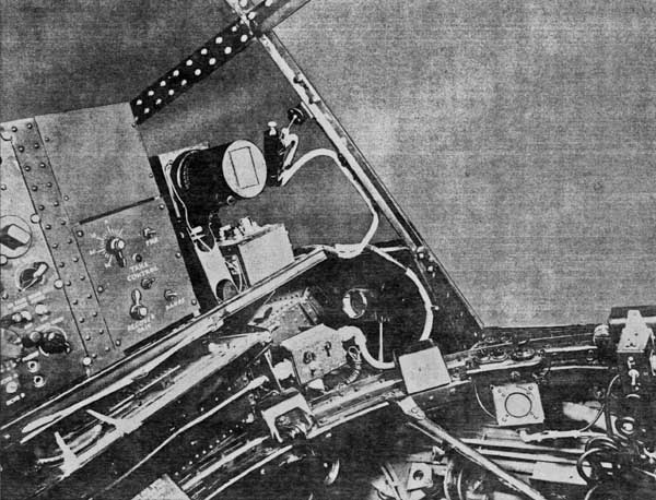
| Observer's Mate Action Station. The UPD-501 receiver indicator
is at the top right and a two band antenna switch is positioned to its
left. Below is the AN/APS-4 display . (From publication - Operating
Instructions for R.C.N. A/S-3 and A/S-3M Aircraft. MICN. 3.10.11A
, courtesy Leo Pettipas). |
AN/APS-20 RADAR
The AN/APS-20 radar was first flown in an XTBM-3(W) Avenger on 5 August
1944. Responding to the system's promise, and to the increasing Kamikaze
threat, the US Navy ordered co-production of the APS-20 while it was still
in development. TBM-3Ws fitted with the AN/APS-20 radar entered service
in March 1945, with some 36-40 eventually being constructed. Eight of these
aircraft would see service with the RCN in 1952.
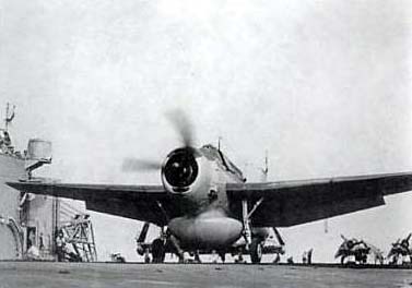 |
| A TBM-3W2 prepares for takeoff from the aircraft carrier HMCS Magnificent.
The bulbous APS-20 radar was employed for both air search and for ASW in
order to detect periscopes and snorkel masts. At this time, it is not known
what variant of the APS-20 radar was fitted into Canadian Avengers. (RCN
photo via Google Books) |
 |
| With APS-20 radome open. The addition of the
bulbous antenna and radome gave the aircraft the sobriquet of "Guppy" (Source:
U.S. Navy Naval Aviation News April 1946) |
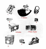 |
AN/APS-20 principal parts. Not all of these components
were used in the Avenger. (Photo courtesy Tpub.com) |
SONOBUOYS
Sonobuoys have three classifications; Passive, Active and Special Purpose.
A Passive sonobuoy listens quietly for submarine sounds in the sea; this
has the advantage of not alerting the submarine that it is being hunted.
An Active sonobuoy uses sound pulses projected into the sea to produce
an echo from a submarine, similar to ping from sonar. Although an Active
sonobuoy locates a submarine more accurately, the sound that it actively
generates into the sea has the disadvantage of warning the submarine that
it is being hunted. Special Purpose sonobuoys have unique functions such
as a bathythermograph sonobuoy which measures the sea temperature at various
depths.
During the 1950s, Canada, UK and USA entered into a tripartite agreement
to standardize sonobuoys to facilitate interoperability. It was agreed
to standardize on a common A size sonobuoy, 4 7/8 inches (124 mm) in
diameter and 36 inches (910 mm) in length. The standardization included
using common VHF radio frequencies to transmit information from the
sonobuoys to the aircraft. Today, this agreement is still adhered to by
NATO countries and their allies. Originally, it was agreed to standardize
on sixteen VHF channels with each sonobuoy allocated one of the sixteen
channels during manufacture but sixteen channels; however, later on, this
proved to be inadequate.
After the sonobuoy enters the water, a hydrophone drops from the buoy
on a suspension cable to listen for submarines. The WWII era sonobuoy,
namely the CRT-1A, had its hydrophone suspended at a depth of 26 feet (8
meters) below the surface as this was thought to be the best depth at which
to detect U-boats. However, as the science of transmission of sound in
water and submarine technology advanced, 26 feet was deemed too shallow;
therefore, the hydrophone of the SSQ-2B (next generation ) sonobuoy was
suspended 40 feet (13 meters) below the surface.
To "fix" a submarine meant to ascertain its position while either on
the surface or attempting to evade being tracked and attacked while submerged.
The Avenger dropped smoke and flame floats to indicate to surface vessels
or other aircraft the submarine's last known position as determined by
visual or radar contact. Another device used in fixing submarines
was the SSQ-2B omni-directional sonobuoy, a cylindrical floating body containing
a sea water activated battery, a VHF transmitter, antenna and a hydrophone.
Upon entering the water the hydrophone dropped from the floating body and
was suspended 40 feet (for SSQ-2) below the surface where it could detect
the propeller sounds from a submerged submarine. If a submarine was detected
while diving, a sonobuoy and a smoke float were dropped at the target's
last known position (At night, a flame float which produced a yellow flame
was dropped). The aircraft then flew a "cloverleaf" pattern around these
indicators, dropping four additional sonobuoys and smoke floats at a maximum
radius of 2,000 meters (2 km) in a 90° position relative to one another.
By aurally monitoring and comparing the relative strengths of the submarine
sounds transmitted from the sonobuoys, the Observer in the Avenger could
plot a rough fix of the submarine's position, commence tracking the target
and direct other cooperating ships and aircraft towards the submarine's
latest fixed position for further localization and attack. The sonobuoys
VHF transmitters in use during the first half of the 1950s had an effective
range of about 10 miles. Internally, the Avenger could carry as many as
sixteen, SSQ-2B sonobuoys, which measured 4 7/8 inches in diameter by 36
inches long (124 mm x 910 mm). The sonobuoy VHF transmissions were received
by two rod antennae fitted to the bomb bay doors and fed to the AN/ARR-26
sonobuoy receiver in the Observer's station.
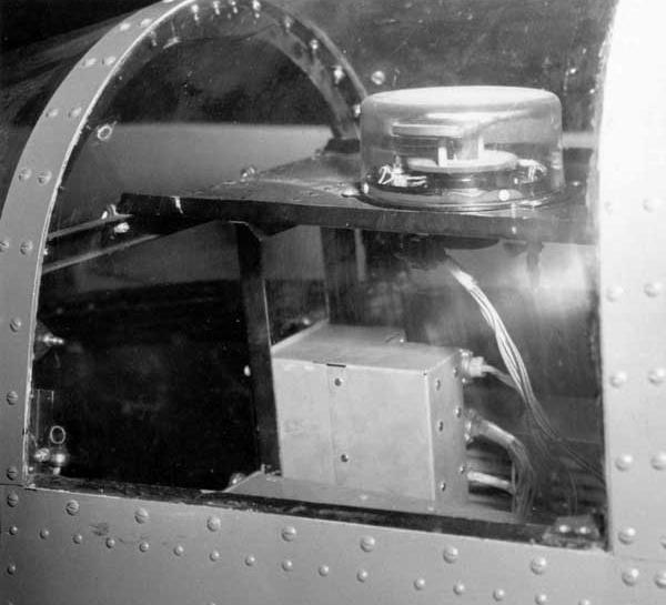
MAGNETIC ANOMALY DETECTOR (MAD)
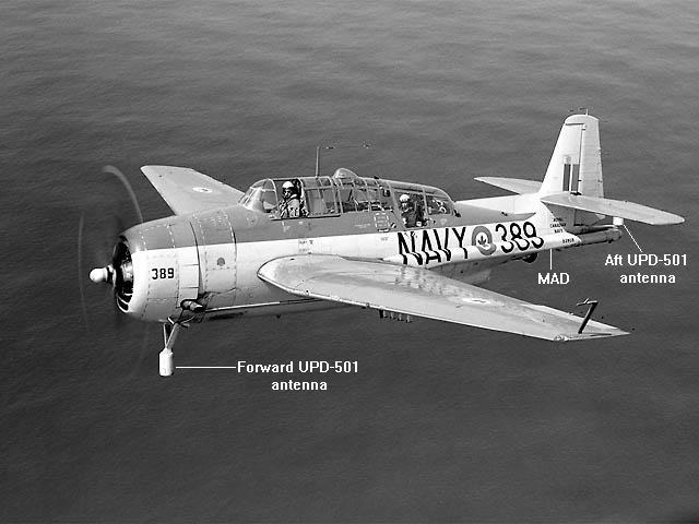 |
This photo of an AS 3M clearly identifies the forward UPD-501 antenna
beneath the engine cowling and the aft UPD-501. Also obvious is the MAD
boom attached the rear port side of the fuselage. Four zero-length
rocket rails are in evidence on the lower surface of the port wing. Most
photos show
the MAD boom in the stowed position. (DND photo DNS-19010) |
One disadvantage of the sonobuoy was that the submarine had
to be making noise before it could be pinpointed. By shutting off the engine
and gliding, the submarine could effectively slip out of the sonobuoy range
and escape. To counter this tactic, the Navy introduced the MAD-equipped
variant of the Avenger. The Magnetic Anomaly Detector, as the name implies,
relies not upon the sounds made by the sub, but by changes caused in the
magnetic field as it moves. Because of its limited range, MAD was unsuitable
for area search. However, it was useful in pinpointing a target that had
been detected by other means.
A major drawback of the available MAD equipment lay with the fact that
the aircraft had to be flown at very low altitudes (50 feet was optimum)
to ensure that maximum signal strength was obtained. This meant that there
was very little warning when a submarine was detected. Sometimes the pilot
subjected the crew to some tight, and at times, uncomfortable manoeuvers.
In addition, certain constraints were imposed while the MAD head was extended:
positive accelerations were not to exceed 2.5 g, and maximum permissible
indicated air speed was to be 196 mph.
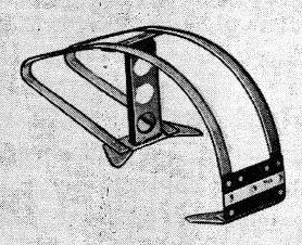
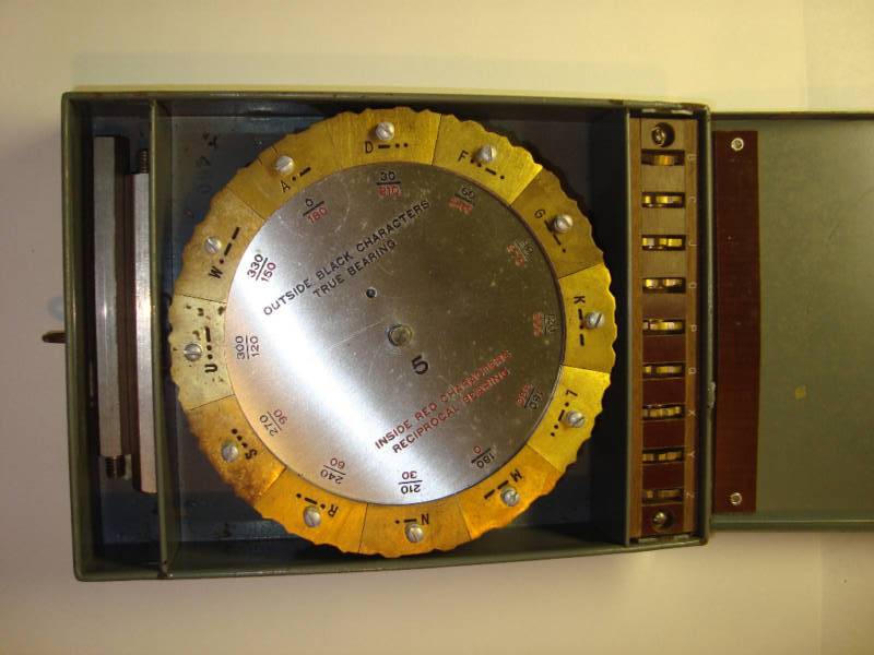
HOMING
During WWII, the USN started using the YE-ZB homing system on its carriers,
a UHF line-of-sight system developed by Frank Akers.
A disk with twelve Morse code characters rotates in sync with a directional
transmitting antenna aboard the carrier. The antenna transmits a
signal which is heard by aircraft returning to the carrier. Every 30 degrees
(360/12) of antenna rotation, the transmitted Morse code character changes.
The pilots hear only one Morse code character, and that character corresponds
to the carrier's transmit antenna being pointed in the direction of the
pilot. If the received letter changed, the pilot knew that the aircraft
was moving tangentially to the transmission point. The pilot usually found
the strongest signal and followed it back to the aircraft carrier
The order and placement of characters on the wheel changed
daily, possibly even with each mission. The transmitter used a double amplitude
modulation scheme and operated around 240 MHz - the double modulation
scheme ensured that a casual eavesdropper would hear only a dead carrier
unless he had the proper demodulator in the receiver.
The Avenger used the AN/ARR-2 VHF homing receiver sometimes called
a "ZB receiver". It is fairly certain HMCS Magnificent was fitted with
the YE transmitter to facilitate homing capability. Click here to see
a photo of a Morse disk used in the YE system . (Ebay photo)
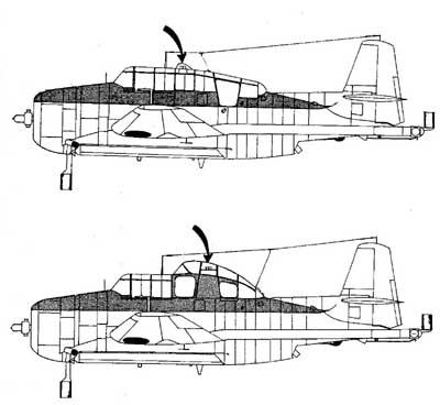
 |
| Location of the "homer" antenna on the Canadian Avenger. It was in
fornt of the pilot , off centre towards the starboard side. |
On the American Avenger the ZB homer antenna is mounted on
the aft end of the starboard bomb bay door. For some inexplicable reason,
the antenna on Canadian aircraft was in front of the Pilot near the starboard
side. Homing antennas were usually located on the underside of the aircraft
to eliminate signal shielding from a surface-based transmitter.
OBSERVERS COMPARTMENT
The Observer's main function was navigation, hence this
compartment contained instruments essential to that trade. The forward
facing panel was rather sparse when compared to the aft facing panel.
 |
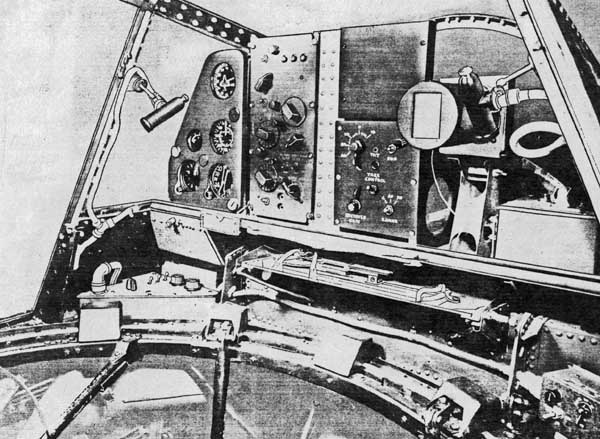
| The Observers Position looking aft in a AS 3M variant. At the top centre
is the radio compass. To its right is the scope for the APS-4 radar. (From
publication - Operating Instructions for R.C.N. A/S-3 and A/S-3M Aircraft.
MICN. 3.10.11A , courtesy Leo Pettipas). |
 |
| Looking forward - port side in both the AS 3 Mk 1 and AS 3M. Not much
here at all. |
 |
| Looking directly forward. Note the absence of instrumentation in the
lower half and the two ARR-26 sonobuoy receivers in the upper half.
This arrangement would be found in the AS 3M and 3M2 variants. |
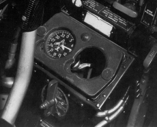
 |
| Looking forward - starboard side. All that was here was a compass
that sat in the upper right-hand corner, facing forward. It was standard
in both the AS 3 Mk 1 and the AS 3M. |
| All photos in this table from publication - Operating Instructions
for R.C.N. A/S-3 and A/S-3M Aircraft. MICN. 3.10.11A. |
 |
| Observer's station port aft quarter in a AS 3 Mk1.(Operating Instructions
for R.C.N. A/S-3 and A/S-3M Aircraft. MICN. 3.10.11A , courtesy Leo
Pettipas). |
 |
| Observer's station starboard aft quarter in a AS 3 Mk1.(Operating
Instructions for R.C.N. A/S-3 and A/S-3M Aircraft. MICN. 3.10.11A
, courtesy Leo Pettipas). |
RADIO CALL SIGNS
When the Navy took delivery of their TBM-3E Avengers the aircraft were
painted overall blue and still bore their American markings and insignia.
As a preliminary measure, the American identifiers were replaced by Canadian
letter codes, roundels and fin flashes. Each machine carried three
white radio call sign letters forward of the roundel on both sides of the
fuselage and on the underside of the port mainplane. The first two letters
were invariably "AB," the standard 826 Squadron code. The third letter
was the individual aircraft's identification number and was also shown
above the fin flash on both sides of the fin and each side of the cowling
ring. When the aircraft were repainted in the two-tone grey scheme the
radio call sign lettering remained in the same positions. Later there were
minor variances in the radio call sign markings.
In 1952, the above-described system of letter codes was abolished and
operational aircraft were assigned radio call numbers that for the most
part corresponded to the number of aircrew carried. Since the early
AS 3 Avenger was manned by a crew of three, each machine was, in theory,
scheduled to receive a 300-block number. The system broke down when
there were more aircraft than there were 300-block numbers to go around.
Since there were more Avengers than there were 300-block numbers, some
of the aircraft had to be assigned numbers from another block until 300-series
numbers were freed up due to write-offs of aircraft that initially carried
them. At the outset, the eight Guppies were allotted the numbers 411 to
418 inclusive even though the number of crewmen normally carried was less
than four. In due course, the 400-block numbers were replaced with 300-series
numerals.
TBM-3W2 "GUPPY"AEW ELECTRONICS
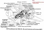 |
This cutaway of an American TBM-3W illustrates
the amount of Air Early Warning (AEW) electronics that were jam packed
into the "Guppy". The majority of it was AN/APS-20 equipment. There is
no cutaway available for the Canadian TBM-3W2 at this time. (Graphic
by Research Laboratory of Electronics, MIT) |
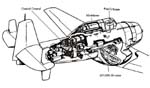 |
This TBM-3W cutaway gives a better idea of how
the crew sat in front of Control Central. (Graphic courtesy tailhookdaily.typepad.com) |
FOOTNOTES:
[1] This was noted by Keith Harrington when the Avengers were being
converted to their civilian roles.
[2] With reference to manual TM 11-487D, Directory of U. S. Army Signal
Equipment Radio Direction Finding Equipment (1958), it does not state who
built the AN/ARD-7. It does, however provide the Signal Corps Stock
Number. SIG 5 is (was) the Signal Corps stock list or catalog.
SIG 5 Subclass 2S lists complete equipment (sets). The Sig Stock
Number for AN/ARD-7 is 2S9300. In the 1955 edition of Subclass 2S,
the 2S9300 entry describes AN/ARD-7 functionally, and ends with:
Lear #ADF-14 or equivalent.
[3] From "The Naval Institute Guide to World Naval Weapons Systems,
1991/92" by Norman Friedman.
QUESTIONS:
1) Was the forward UPD-501 antenna for the X or S band in a two antenna
configuration?
2) Who made the CAM-1 interphone system?
3) On page 62 of the book "Certified Serviceable" it clearly states
the ARC-27 UHF radio replaced the ARC-1 VHF radio. Can anyone confirm if
the Avenger was then left without any VHF capability? It's hard to
imagine an Avenger operating ashore in a civilian air traffic control environment
without a VHF radio in the 1950's.
Please reply to: Jerry.Proc@sympatico.ca
Credits and References:
1) Leo Pettipas <lpettip(at)mts.net> Associate
Air Force Historian. Air Force Heritage and History 1 Canadian Air Division.
Winnipeg, Manitoba.
2) White Paper: Grumman ASW Avenger Variants
in the RCN by Leo Pettipas. June 2008
3) White Paper: Early Cold War Anti-Submarine Warfare
Development in Canada by Leo Pettipas. June 2008
4) Ernest Cable - Associate Air Force Historian and
Shearwater Aviation Museum Historian <erncar(at)ns.sympatico.ca>
5) Robert Langille (ewcs(at)ewcs.ca>
6) ARR-3 photo http://www.history.navy.mil/library/online/radar-14.htm
7) ARR3 info http://www.vk2bv.org/museum/arr-3.htm
8) AN/APX-2 http://www.ibiblio.org/hyperwar/USN/ref/Radar/Radar-13.html
9) ART-13 photo - Collins Club Radio page
http://www.collinsclubs.com/carc/b-29/radio.html
10) Keith Harrington va7ssb(at)hotmail.com
11) Robert Downs <WA5CAB(at)cs.com>
12) ASQ-8 http://www.tpub.com/content/radar/TM-11-487C-1/TM-11-487C-10951.htm
13) ARC-1 Control Panel. Google Books: Grumman TBM Avenger
Pilot's Flight Manual
14) APN-20 Control Box http://www.bpbsurplus.com/lc/cart.php?target=product&product_id=17878
15) ANP-1 photo http://www.vk2bv.org/museum/apn1.htm
16) ARC-27 photo http://www.radiosamling.dk/Specifikationssider/Military_Radios/Mi_021.html
17) ARC-1 photo. Surplus Conversion Handbook #122
by Tom Kneitel. 1964
18) ARR-2 photo http://en.wikipedia.org/wiki/File:ARC-5_RCVR.jpg
19) ARR-2 info http://noding.com/la8ak/61.htm
20) ARC-9 info http://www.radiomilitari.com/arc9.html
21) ARR-3 diagram http://www.history.navy.mil/library/online/radar-14.htm
22) ARC-9 photo http://www.radiomilitari.com/arc9.html
23) ARN-21 photo http://members.home.nl/a.k.bouwknegt/
24) ART-26 info: http://www.tpub.com/content/radar/TM-11-487C-1/TM-11-487C-10945.htm
25) CMA-301 info http://www.flightglobal.com/pdfarchive/view/1957/1957%20-%200498.html
26) APX-6 http://members.home.nl/a.k.bouwknegt/index_bestanden/APX6.htm
27) TBM-3W cutaway http://tailhookdaily.typepad.com/tailhook_daily_briefing/2009/01/fligh
tdeck-friday-history-of-carrier-aew-ii.html
28) David Ross <ross(at)hypertools.com>]
Back to Avenger
Main Document
Jul 31/10


