|
SENSORS
|
| |
| DEVICE |
YEAR |
DESCRIPTION |
|
|
|
| AN/APS-506 |
Legacy (1980) [1] |
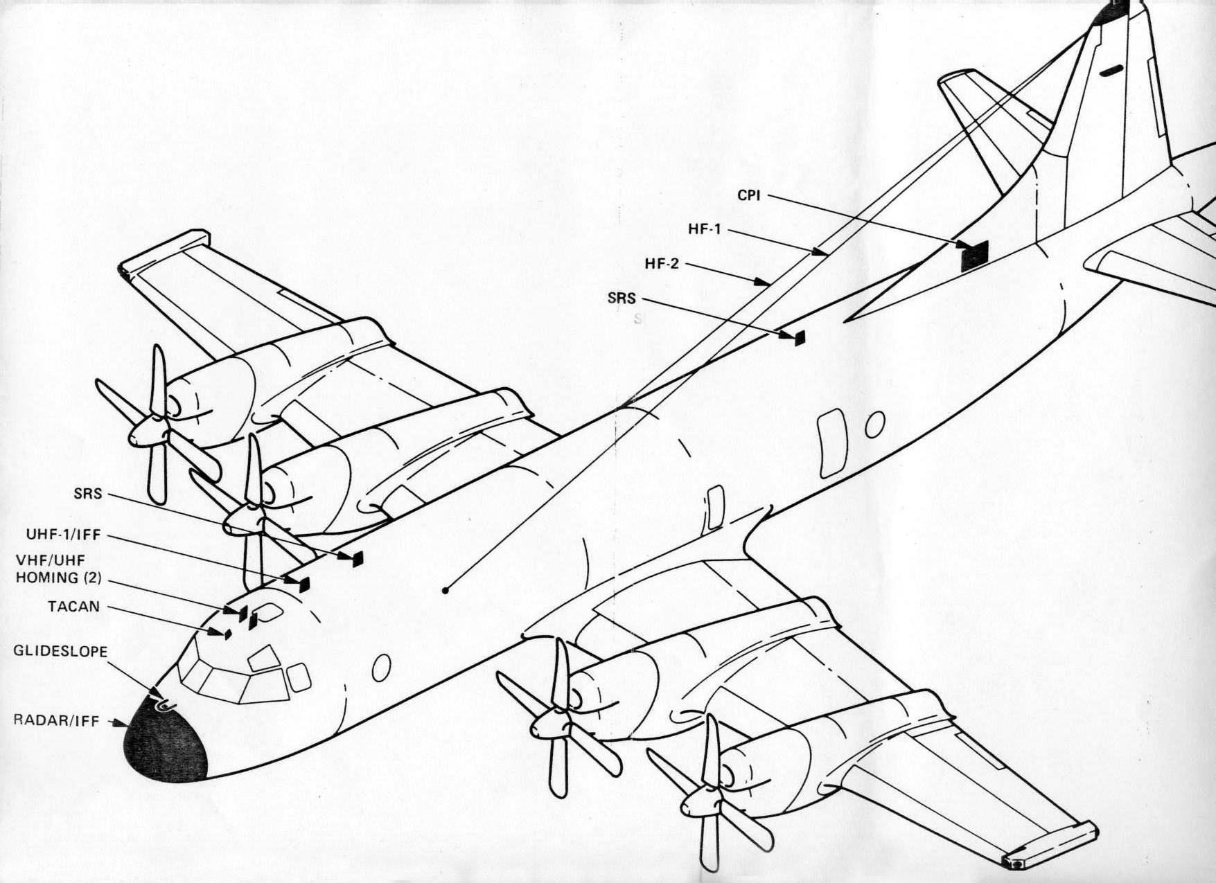
This is a two dimensional, surface search radar and the Canadian designation
for the AN/APS-116A radar manufactured by Raytheon/Texas Instruments. It
has three modes of operation - periscope and snorkel detection, search
and navigation, and ocean search for online operation . Only mode 2 (search
and navigation) can be operated offline. In Mode 3 (long range),
targets can be detected up to 280 kilometers (150 nm) approx. Fitted in
CP-140 only,
This radar is retained in Block I and Block II upgrades but changes
in Block III to AIRS. |
| AN/APS-507 |
Original, 1991 |
Multimode surface search radar manufactured by Raytheon/Texas
Instruments. Fitted in Arcturus CP-140A only. Incorporates the "track-while-scan"
feature. It is the Canadian version of the AN/APS-134.
It has three operational modes (periscope, navigation and search) that
facilitate a span of capabilities from detection of small targets in high
sea states to medium range navigation and weather avoidance usage. A Track-While-Scan
(TWS) feature enables the operator to select up to 32 targets for automatic
tracking in the Navigation and Search modes. A nose mounted antenna
provides 240 degree coverage (120 degrees either side of aircraft nose)
of the 360 degree antenna rotation. The system is controlled from a radar
operator station unique to the CP-140A. |
| AIRS |
2010 > |
AIRS, the Imaging Radar Project (MDA Contract), replaces the existing
AN/APS-506 radar system in Block III with the new Imaging Radar System
(IRS) and partially replaces the IFF/SIF system with the new IFF Interrogator
Subsystem (IFFIS). The integration of these two entities is known as the
Airborne Imaging Radar Systems (AIRS). Associated with the AIRS is the
Ground Imaging Radar System (GIRS) designed to process, archive, and exploit
stored radar imagery. In addition to current maritime surveillance, navigation
and weather capabilities, AIRS will also give the aircraft a number of
new Synthetic Aperture Radar (SAR) and IFFI capabilities: Strip map, Land
spot, Sea spot, ground moving target indicator (GMTI), upgraded IFF interrogation
modes, search and rescue (SAR).
The IFFI can be operated offline (can only display modes 1, 2, or 3/A)
or online (generating interrogations in any combo of up to 5 modes). It
is capable of Mode 1, 2, 3/A, C, 4, S level 2, and 5 level 2.
Radar modes of operation include surveillance (WX - weather, NAV -
navigation, LRCS - low radar cross section, WAS - wide area surveillance,
and GMTI - ground moving target indication), imaging modes (Strip map -
image a continuous swath of land at low to high resolution, Land spot -
image a fixed/geodetic land surface point in medium to high resolution,
and Sea spot - image a fixed or moving maritime target in low to ultra-high
resolution), interleaved modes (A Scan Plot - aids operator in classifying
a target by radar profile, including length and dominant scatters and Search
and Rescue Transponder (SART) aids in the location of transponders),
and combination modes (WAS/NAV, WAS/WX, NAV/WX). |
| OR-5008/AA |
Legacy (1980) [1] |
FLIR Imager. (OR-89 derivative). Click on link for details. |
| AN/ASX-4 |
2007 > |
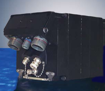
aka Wescam MX-20. This is a Electro-Optical/Infrared (EO/IR) system
made by L3 Wescam and is found on the Block II and III aircraft. It provides
the CP140 a long-range imaging surveillance capability able to passively
sense visual band and infrared radiation from targets and objects of interest.
The EO/IR provides high magnification colour and monochrome day TV cameras
and an infrared camera with step zoom capabilities. Remote pointing of
the camera sensors is achieved through the motorized, gyro-stabilized gimballed
turret in which they are mounted. The sensor turret is mounted aft and
below of the CP140 nose radome, under the flight deck, on a motorized extendable-retractable
mechanism. Three cameras housed in the turret provide continuous, simultaneous
video when the system is ON. The cameras are identified as: a. EON - for
the narrow field of view, long range spotter scope identification camera.
b. EOW - for the wide field of view, colour camera. c. IR - for the infrared
camera. The turret comprises two subsystems; the payload and the
gimbal. The payload provides 360-degree continuous azimuth field of view
with three imaging sensors that support long range day and night surveillance
missions as follows:
a. The Electro-Optic Wide (EOW) field of view sensor; a 1.6 to 30 degree
field of view, continuous zoom, electro-optic imaging sensor with selectable
colour or monochrome video output.
b. The Electro-Optic Narrow (EON) field of view sensor; a 0.11 to 0.61
degree field of view, discrete zoom, electro-optic imaging sensor with
monochrome video output.
c. The IR sensor; a 0.29 to 21.7 degree field of view, discrete zoom,
IR imaging sensor with monochrome video output.
Unit cost is approximately $1 million, depending on options. |
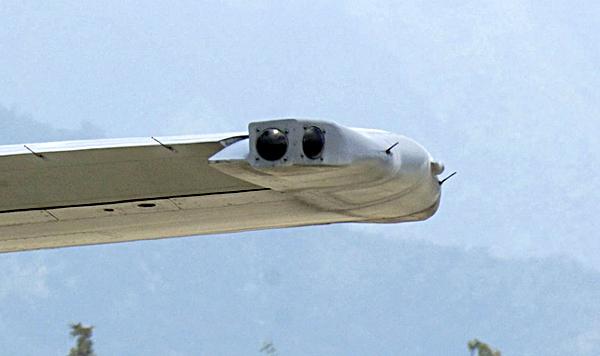
| AN/ALR-502 |
Legacy (1980) |
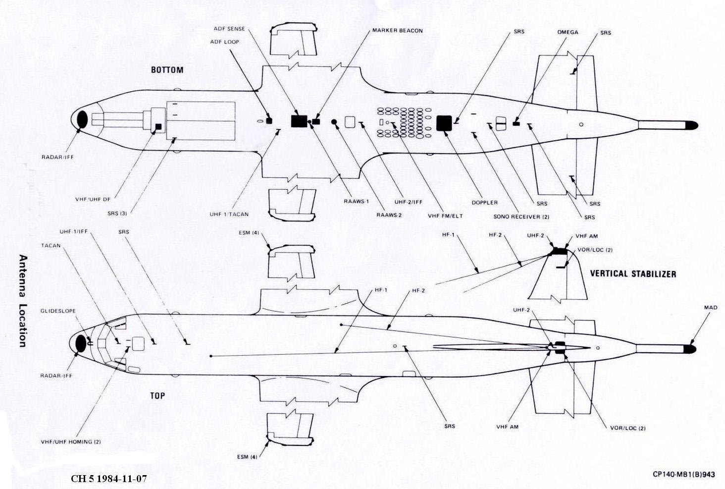
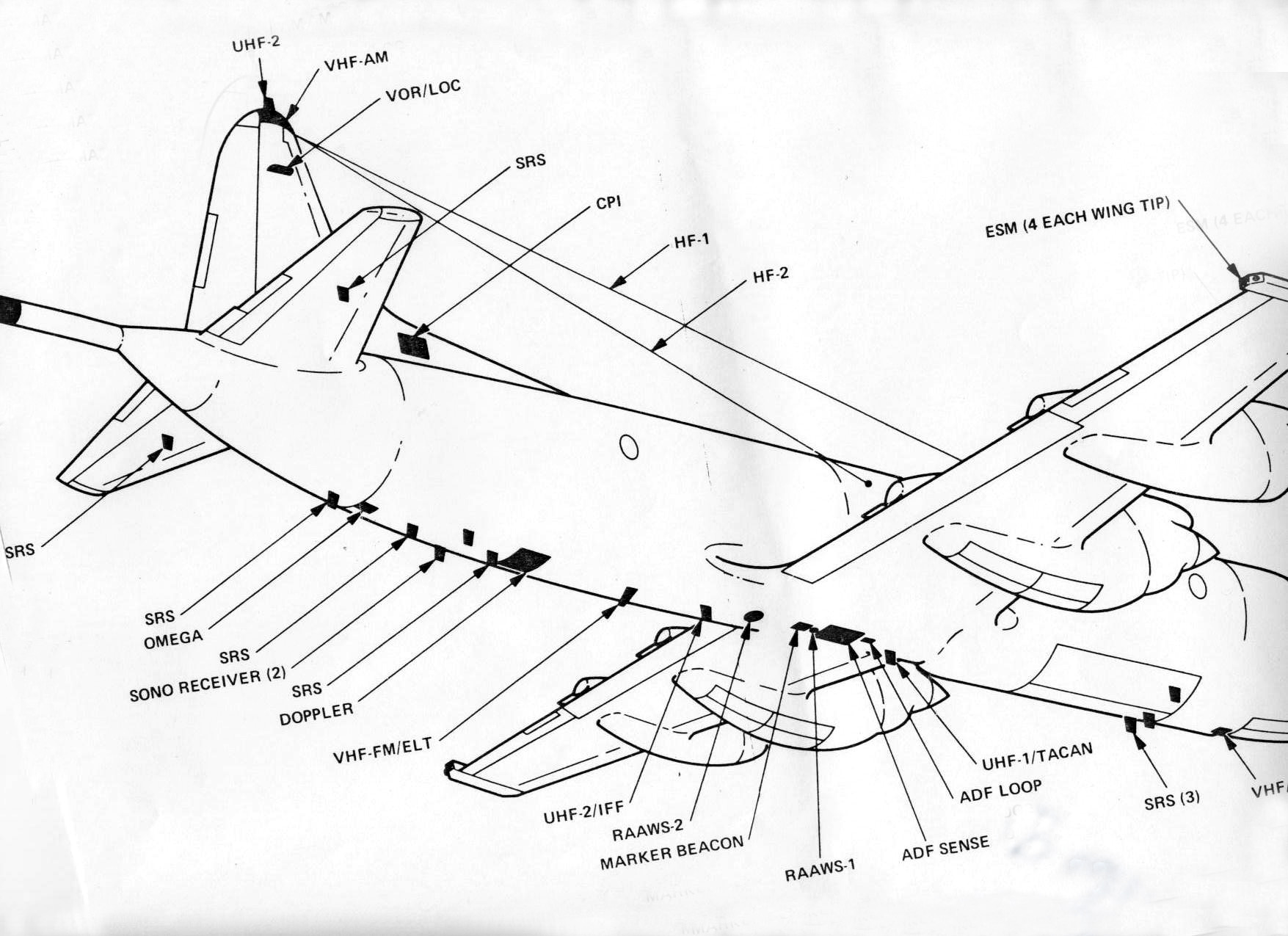
Canadian designation for the AN/ALR-47 ECM made by IBM. It is an
emitter-location system with four receiver antennas fitted into each CP-140
wingtip. Used to locate adversary radio and radar transmitters. |
| AN/ALQ-217 |
2010 > |
An ESM system manufactured by Lockheed-Martin and is found on the Block
III CP-140M (circa 2010). This ESM provides the aircraft with the capability
to passively detect, identify, analyze, and locate RF emitters. It consists
of 4 quadrant antenna arrays (QAAs) each consisting of 2 mid band antennas,
2 high band antennas, and 1 low band/guard channel antenna, two active
front end (AFE) receivers, and a receiver/processor. It uses two narrow
band, rapid scanning, superheterodyne receivers to detect and measure the
following primary parameters: angle of arrival (AOA), pulse repetition
interval (PRI), radio frequency (RF), amplitude, pulse width (PW), scan
interval, and location. It provides 360 degree of azimuth coverage (+ or
- 30 degrees of antenna elevation coverage) at all frequencies within its
search envelope. |
| AN/ASQ-502 |
Legacy (1980) |
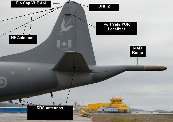
Magnetic Anomaly Detector (MAD). Although it was
loosely based on the MAD design from the S3 Viking, it is a uniquely Canadian
system. Made by CAE, Montreal , the cesium magnetometer detecting head
can detect a change of 1 in 5 million in the Earth's magnetic field - the
most sensitive unit available when the CP-140 came into service. |
| OA/5154/ASQ |
Legacy (1980) |
MAD Compensator built by CAE Montreal. The 16-term Fully Automatic
Compensation System (FACS) conditions the raw magnetometer data, using
its mini-computer for displays and other aircraft systems. The other necessary
input is the orthogonal vector magnetometer signals which provide heading,
manoeuvre and total earth-field data. The use of completely electronic
compensation obviates the need for output coils to generate opposing fields
and no operator input is needed. The compensation flight programme lasts
for no more than six minutes and comprises four one-minute low amplitude
manoeuvres on headings approximately at right angles to each other. Additional
trapping circles and cloverleaf manoeuvres are optional. As well as automating
the recompensation exercise, the FACS allows the operator to update the
system with minor magnetic variations at the touch of a button. |
| AN/ASQ-502(V) |
2007 > |
AN/ASQ-508(V) Advanced Integrated MAD system is only found on the Block
III aircraft. It has greater sensitivity and sampling rate than the legacy
system. There are 3 types of MAD trace outputs: Bandpass MAD - same as
legacy MAD trace, Adaptive MAD - processed to minimize eternally generated
interference (e.g. geo, solar, and wave noise), Scaled Adaptive MAD - more
closely resembles traditional bandpass MAD amplitudes. Automatic continuous
16 term compensation of the interference field at the sensor due to the
aircraft's permanent, induced, and eddy current generated magnetic fields.
It automatically displays the slant range in feet, target confidence level,
and signal amplitude of any contacts and it capable of displaying an evaluation
of the compensation quality, the local geological activity, the current
FOM, and the noise threshold levels. |
| AN/SSQ-530(3) |
From 2004
photo |
An "A" size, 31 channel Jezebel Sonobuoy with Directional
LOFAR (DIFAR) capability. Made by Sparton. Has four presettable hydrophone
depths ranging from 30 to 300 meters. An improved version of the AN/SSQ-53A.
Battery life is 1 to 4 hours. |
| OL-5004/AYS ADP |
Legacy (1980) [1] |
Acoustic processor for sonobuoys |
| SB 5123/AYS |
Legacy (1980) [1] |
Sonobuoy Monitoring System (SRS). |
| AN/AQH-501 |
Legacy (1980) |
Airborne, acoustic tape recorder to record sonobuoy audio. |
| R-1741 |
Legacy (1980) [1] |
Sonobuoy receiver |
| AN/ARS-501 |
Legacy (1980) [1] |
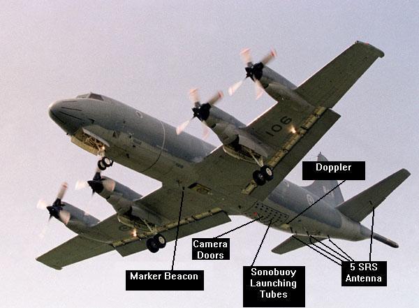
The Sono Reference System (SRS) is found on the pre-Block I CP-140
(not the CP-140A). SRS is comprised of the SBRS (Sonobuoy Bearing Receiving
Set) and the SRS subprogram. The SBRS provides relative sonobuoy
bearing data to a selected sonobuoy to the GPDC. The SRS subprogram then
uses interferometer techniques to continuously compute and update the geographic
position of sonobuoys in concert with the aircraft's navigation system
without having to overfly the sonobuoy. The SBRS operates exclusively on-line
and interfaces only with the AYK-502 computer. The Sonobuoy Bearing Receiver
(SBR) is a 31 channel, fixed-tuned VHF system. Its 10 antennae receive
the phase difference between 16 antenna pairs for selected frequencies
This phase difference is processed and encoded in digital format and sent
to the GPDC for bearing and position compilation.
Note; Sonobuoy Receiver (SRX) is only found on the Block III CP-140M
aircraft (circa 2010). The aircraft has two SRX's providing the capability
to receive transmissions and locate up to 99 standard "A" size NATO sonobuoys. |
| AN/AYK-502 (V) |
Legacy (1980) [1] |
Tactical Computer. Canadian version of AN/AYK-10 which is based on
the 32 bit Univac 1832 machine and utilizing 65 k of memory. The outputs
of the ASW mission sensors are integrated by the AN/AYK-502 digital processor.
Sensor Integration is achieved by controlling and displaying contact information
from common key boards and multi-purpose displays. The AYK-502 also provides
sensor libraries. For example, the computer system stores a library of
sensor signatures that narrows the search parameters and alerts the sensor
operator when a match is detected that meets the library parameters. |
| VASP System |
2010 > |
The VME Acoustic Signal Processor (VASP) System is only found on the
Block III CP-140M aircraft (circa 2010 and later). VASP provides the aircraft
with the capability to detect, localize/fix, classify, and track subs and
surface vessels from passive, active, and multistatic active acoustic data.
The VASP processes acoustic data from the sonobuoys, digitizes it, extracts
the essential characteristics for presentation to the operator in both
audio and video form. |
| AN/APX-502 |
Legacy (1980) [2] |
IFF SIF/interrogator-synchronizer (along with its associated transponder
set AN/APX-77A) generates and transmits pulse-coded radar challenge signals
to interrogate surface and airborne targets, which automatically respond
by transmitting an identification code. |
| RT-8620A |
Legacy (1980) |
IFF Receiver -Transmitter |
| AN/APX-76 |
Legacy (1980) |
IFF/SIF airborne Receiver Transponder .D-band (1 to 2 GHz). The legacy
unit used vacuum tubes. Later on, it was followed by the solid-state
transmitter AN/APX-76B and the technically improved product AN/APX-76C
but it is not known if the CP-140 used any of these update versions. |
| AN/UPX-40 |
2007 > |
IFF. Mark XIIA all mode interrogator. Features new
Mode S/Mode 5 which enhance performance, improve security and heighten
situational awareness. Made by Telephonics Corp. It might be part
of the kit that was added with Block II modifications. The only follow
on IFF upgrades are embedded in the radar system for Block III. |
| AN/SSQ-536G |
Bathythermograph |
|
|
|
|
| COMMUNICATIONS - Legacy CP-140 including
CP-140A |
| |
|
|
| DEVICE |
YEAR |
DESCRIPTION |
|
|
|
AN/ARC-511
aka 618M-3A |
Legacy (1980) |
This is a VHF-AM radio, made by Collins. The radio set is primarily
used by the pilot and copilot to communicate with Air Traffic Control (ATC)
facilities and can also be used for direction finding (DF) or homing. VHF-AM
frequency range: 116.0-151.975 MHz in 25-kHz increments. Modes are selected
at the Flight Station. Power output is 25 watts nominal |
| AN/ARC-512 |
Legacy (1980) |
Two of these were fitted in all pre-Block 1 CP-140 and the CP-140A.
Two HF Radio Sets, identified as HF-1 and HF-2, provide long range, two-way,
communications. Both provide plain or cipher teletype, plain or cipher
data link and plain voice communications. Although the radios are the same
in both aircraft, CP-140A is not equipped to utilize teletype or data link.
The CP-140A HF radios have been configured for secure HF voice communications
though. Power output is 100 Watts, 500 Watts, or 1000 Watts. Mode of operation:
LSB voice, USB voice, AME voice, USB-FSK teletype, USB data link, and USB
and LSB diversity data link communications. |
| ARC-513(V2) |
Legacy (1980) |
The VHF-FM radio allows voice communications with government agencies,
maritime mobile units and the simultaneous monitoring of the VHF maritime
mobile emergency frequency (156.8 MHz).
9600 channels from 150 to 174 MHz with 2.5 KHz spacing.
The radio is also used for direction finding (DF) or homing. The VHF-FM
radio can be used to provide aural monitoring of sonobuoy signals plus
DF or homing to a particular sonobuoy since the sonobuoy frequencies lie
within the ARC-513(V) frequency range. The Receiver-Transmitter has two
separate receivers; the main receiver which can be tuned to any frequency
within the frequency band and the guard receiver which is tuned to 156.8
MHz, the maritime mobile emergency frequency. The Receiver-Transmitter
has two selectable transmitter output powers, either 1 or 10 watts. Within
the frequency band covered by the Receiver-Transmitter, eleven channels
can be preset by maintenance personnel to aid in radio set operation; but
any of the 9600 available channels can be selected for Receiver-Transmitter
operation by using the control panel manual frequency selectors.
HF Radio Set manufactured by Allied-Signal Inc. Consists of the RT-5052
/ ARC-513 R/T, C-5333 / ARC-513 Control, and AS-5013 / ARC-513 Antenna. |
| AN-ARC514(V) |
Legacy (1980) |
AN/ARC-514(V) UHF - Two of these radios are found on the CP-140 (pre-Block
II) and CP-140A. Two UHF Radio Sets, identified as UHF-1 and UHF-2, provide
line of sight, two-way, plain or cipher voice communications and the simultaneous
monitoring of the UHF guard frequency (243.0 MHz). Both have provisions
to be used for satellite communications and sonobuoy command. UHF-1 or
UHF-2 radio transmissions can only be made from the pilot, copilot, TACNAV,
and NAVCOM stations but all crew positions can monitor the radio signals.
UHF-1 also provides Direction Finding (DF) and homing capability. The UHF-1
frequency, mode, and antenna are selected at the FLT STA. UHF-2 also provides
plain or cipher Teletype (TTY) and plain or secure data link capability.
The UHF-2 frequency, mode and antenna are selected at the TACNAV/NAVCOM
console. Each receiver-transmitter has two separate receivers: the main
receiver which can be tuned to any frequency within the frequency band
of 225-399.975 MHz in 0.025 MHz steps; and the guard receiver which is
preset to 243.0 MHz. |
| AN/PRC-66B |
Pre AIMP |
The AN/PRC-66B radio set is a self contained, auxiliary UHF transceiver
that provides plain voice communications. The set is a stand alone unit
and is not integrated with the Communication System Control Group. It permits
two-way plain voice UHF communications, however there are no provisions
for monitoring of ICS (intercom) or other audio. The AN/PRC-66B is
a single-channel transceiver unit that can be tuned to any frequency within
the frequency band of 225.00 to 399.95 MHz in 0.05 MHz steps.
AN/PRC-66 photo courtesy Army Radio.com |
| AN/AGC-501 |
Legacy (1980) |
Radioteletype (RATT) System - not found in the CP-140A. The RATT communication
system provides two-way plain or cipher teletype communication between
own aircraft and other similarly equipped aircraft, ship or shore stations.
The RATT communication system provides for the automatic on-line mode transmission
of teletype messages from the General Purpose Digital Computer (GPDC) or
the manual off-line mode transmission from the TTY. The teletypewriter
(TTY) contains a keyboard and a solid state logic unit. The TTY generates
alphanumeric RATT messages for HF-1, HF-2, or UHF-2 Radio Set transmission. |
| Link-11 Data
Link |
Legacy (1980) |
Not found in the CP-140A, only CP-140. This is a Link 11 system comprising
of a data terminal set J-5262/AYC, and a Data Link Security Unit KG-40.
Link-11 is a medium speed, HF/UHF, tactical data information link. It employs
netted communication techniques and standard message formats, for the exchange
of digital information among airborne, land based and seaborne platforms.
Any one of HF-1, HF-2, or UHF-2 can be used to conduct Data Link communications.
Two audio waveforms are provided by the DTS; the Conventional Link Eleven
Waveform (CLEW) which consists of 16 phase modulated audio tones and the
Single-tone Link Eleven Waveform (SLEW) which consists of a single phase
modulated audio tone. The SLEW waveform provides superior error correction
and signal-to-noise performance over CLEW. This system only works online
in concert with the GPDC (general purpose digital computer) via the Manchester
serial channel in pre-Block I CP-140 and via the 1553B Data Bus in post
Block I CP-140. In Block III, the CP-140M has the same Data Link kit; however,
due to the increased capability of the mission computer that replaces the
AYK-502, Link 11 functionality is greatly enhanced and there is a possibility
of expansion to Link 16. |
| KY-58 |
Legacy (1980) |
Voice encryption equipment. |
| KW-7 |
Legacy (1980) |
Radioteletype encryption equipment with KWX-7 remote control. Now superceeded. |
|
|
|
| COMMUNICATIONS - Legacy and Pre Block I
Radio Suite (CP-140 only) |
|
|
|
| AN/ARC-511 |
Legacy (1980) |
RT-5048 VHF AM radio set. Same as above. |
| AN/ARC-513(V2) |
Legacy (1980) |
VHF FM radio set. Same as above |
| AN/ARC-514(V) |
Legacy (1980) |
UHF radio set. Same as above |
| AN/ARC-512(V) |
AIMP, 1997 > |
This was an improved version of the HF radio set. - there are 2 of
these on each aircraft (upgraded version of the radio fitted in Block 1
and all follow-on CP-140/M). Modes are: LSB voice, USB voice, AME voice,
USB-FSK teletype, USB data link, Independent Sideband (ISB) voice, data,
RATT or link 11 and USB and LSB diversity data link communications. It
also offers Automatic Link Establishment (ALE), Selective Calling (SELCAL)
(receive only) and LINK 11 compatibility. The radio is well suited for
Simultaneous Operation (SIMOP) where two or more HF radio systems may be
operating in close proximity. The minimum frequency separation between
the two HF radio sets is 2 MHz or 10 per cent of the higher frequency,
whichever is greater. During SIMOP the power setting shall be set to medium
or low. Amplifiers provide operation at the following power levels: 100,
500 or 1000 watts. |
| AN/PRC-66B |
Pre AIMP |
Auxiliary UHF Radio - same as above |
| AN/AGC-501 |
Legacy (1980) |
Radioteletype (RATT) System - same as above |
| AN/AIC-503 |
Legacy (1980) |
Intercommunications system. |
| AIRSAT 1 |
2000 > |
AIRSAT 1 Iridium Aeronautical Satellite Communication System - The
Iridium System is a satellite-based, wireless personal communications network
that provides global telephone coverage. The subscriber equipment
used aboard the CP140 is the AIRSAT Single Channel Satellite Communications
System (SATCOM) with Voice/Data capability. The Iridium Transceiver Unit
(ITU) 100 is a single-channel transceiver unit that contains the circuitry
to send and receive digital telephone calls and provide two-way internet
access using the Iridium satellite-based communications network. The channel
rate is still 2.4 Kbps, but up to 10 Kbps effective throughput can be achieved
depending on content. Graphics and images will result in lower effective
throughput. For example, a typical 100 Kb image captured with the DCS-620
camera requires approximately four minutes to download. This was retrofitted
into the CP-140 for Operation Apollo in 2000 and has become standard kit
for all CP-140. It is not found on the CP-140A.
Frequency Range: 1616 - 1626.5 MHz
RF Power Input: 6 Watts (max.) |
|
|
|
| COMMUNICATIONS - Block II and Block
III Radio Suite (CP-140/M) |
|
|
|
| AN/ARC-511 |
Legacy (1980) |
VHF AM radio set - same as above |
| ARC-513(V2) |
Legacy (1980) |
VHF FM radio set - same as above |
| AN/ARC 512(V) HF |
Legacy (1980) |
(Improved) HF radio set - same as above |
| AN/PRC-66B |
Legacy (1980) |
Auxiliary UHF radio set - same as above |
| AN/AGC-501 |
Legacy-partial |
Radioteletype (RATT) system. Some components are the same as above
but much of the functionality has been incorporated into the upgraded Data
Management System (e.g. keyboard, interface) and the HSP (high speed printer)
has been upgraded. |
| AIRSAT 1 |
2007 > |
Iridium Aeronautical Satellite Communication System - same as above. |
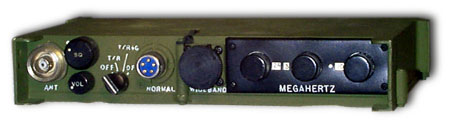
| AN/ARC-210(V) |
AIMP, 1997 > |
VHF/UHF Radio. Quantity 3 fitted. The AN/ARC-210(V) integrated
communications system made by Rockwell Collins is designed to provide multimode
voice and data communications in either normal or jam-resistant modes through
software reconfiguration. The RT-1556 transceiver is capable of establishing
two-way communication links over the 30 to 400 MHz or 30 to 512 MHz frequency
ranges within tactical aircraft environments. Output power is 10 to 15
W (AM) and 15 to 23 W (FM) (FM 400 to 512 MHz is 5 watts). The system may
be controlled via MIL-STD-1553B and can be tuned in 2.5 KHz steps. A local
controller, the C-11896/7/8, is available in white, red or green lighting
respectively and will tune the system in 5 KHz steps. Remote frequency
indicator ID-2428 provides frequency and mode displays. The ARC-210 system's
frequency plan and ECCM data may be filled remotely or locally by the AN/CZY-10
Data Transfer Device. A family of electronically tunable antennas is available.
A SATCOM model (RT-1747B) has been developed to enable the ARC-210 to interface
with a variety of modems and the system is capable of supporting 5 KHz
or 25 KHz DAMA operation. The RT-1747C has European ATC 8.33 kHz tuning
added. The system also includes a remote controller for manual operation
of the transceiver, a remote indicator and a family of broadband and electronically
tunable antennas.
Also known as a V/UHF terminal, ARC210 is satcomm capable, however
that capability cannot be used in the Aurora because the antennas
not capable of satcomm reception.
Photo of control unit. (Courtesy Rockwell
Collins) |
| AN/ARC-234V |
AIMP, 2007 > |
UHF Satcomm terminal. (also referred to as the V/UHF 4 in the aircraft).
The AN/ARC-234 Airborne Integrated Terminal Group (AITG) is a software
programmable half-duplex UHF/VHF DAMA SATCOM airborne-qualified terminal
designed to be compatible with the USAF standard DAMA-capable UHF SATCOM
terminal. It is designed to provide UHF SATCOM operation in a high co-site
environment on aircraft with multiple emitters, or when operating in the
vicinity of friendly ground troops using high power VHF and UHF equipment.
AITG also operates in the VHF band providing SINCGARS and 8.33 kHz channelization
for European Air Traffic Control. The AITG includes the receiver/transmitter
(AIT), the LNA/diplexer, the mounting tray and a remote control unit (RCU).
The AIT weighs approximately 23.4 kg. Power operation on 115 VAC or 28
VDC. It operates in the 30 to 512 MHz frequency band which covers Army
FM (30 to 90 MHz), Air Traffic control (108 to 128 MHz), land mobile (128
to 160 MHz), UHF LOS (225 to 400 MHz), UHF SATCOM (270 to 320 MHz)
and UHF land mobile/special purpose (405 to 512 MHz) .It includes an embedded
DAMA modem and embedded COMSEC. The modem is interoperable with the MD-1324
DAMA modem and also operates in high speed UHF SATCOM mode per MIL-STD-188-181B.
The modem will run from 75 bits/s to 48 kbits/s in the SATCOM mode and
at up to 64 kbits/s in the LOS mode. Embedded COMSEC functions include
KY-58, KYV-5, KG-84 and KG-10 and KG-11 TRANSEC devices. The AIT can be
controlled via the RCU, military data bus or a laptop computer.
With the exception of the batwing antennas that have been installed
on the Aurora, it's pretty much the common ARC-234 system that can
be found in today's market. |
|
|
|
| NAVIGATION Pre Block II (Legacy CP-140
including CP-140A) |
| |
|
|
| DEVICE |
YEAR |
DESCRIPTION |
|
|
|
| AN/ASN-502 |
Legacy (1980) |
Inertial Navigation System (INS). aka Litton LN33. Two systems were
carried aboard the aircraft. |
| AN/ARN-508 |
Legacy (1980) |
VOR/ILS/Marker Beacon (MB) - The VOR/ILS/Marker Beacon navigation system
provides the pilot, copilot, and NAVCOM with aircraft bearing and course
deviation information with respect to a ground VOR station. Localizer,
glide slope and Marker Beacon information is displayed in the FLT STA.
The Glide Slope (GS) receiver (incorporated within the VOR Receiver) operates
in the 329.15 to 335.0 MHz frequency range. The Marker Beacon antenna receives
75 MHz ground beacon signals. These signals are split by the Antenna Coupler
in Rack 10 and sent to the VOR-1 and VOR-2 Receivers for demodulation to
determine marker type. Receiver output does not interface through the ANIB.
Modulations of 400 Hz, 1300 Hz, and 3000 Hz respectively illuminate the
OUTER (blue), MIDDLE (yellow), and AIRWAYS (white) lights. Reception of
an inner marker will cause the AIRWAYS light to illuminate. Marker Beacon
audio is available when RECEIVERS is selected to BCN on the respective
pilot and copilot ICS Master Control panels. Marker Beacon sensitivity
is not selectable. |
| AN/PSN-10(V) |
1991 > |
Global Positioning System. - is a stand-alone navigation system
which uses the 24 satellites constellation called NAVSTAR. Hardware includes
a GPS receiver and a GPS antenna. The GPS navigation receiver is a portable
system which uses C/A code (Course/Acquisition), L1 (1575.42 MHz ) frequency
to provide position, velocity and time to the user. The system also calculates
waypoints, steering, and navigation data. The GPS information is available
only at the NAVCOM station, and is not associated with the Integrated Navigation
System. The AN/PSN-10(V) Receiver provides worldwide day/night, all weather
position and velocity data. It utilizes three sequencing signal processing
channels to compute three-dimensional position and velocity and to manage
and maintain the satellite tracking process. The receiver also receives
GPS satellite signals using a fixed-pattern antenna and displays time-tagged
position and velocity at intervals of approximately one second. Output
information may be communicated digitally via an RS-422 Data Channel at
a data rate of 9600 baud. These were retrofitted into the CP-140A in the
late 1990's to provide GPS information following the demise of the Omega
hyperbolic navigation system in 1997. |
| AN/ASN-505 |
AIMP, 1997 > |
Dual Inertial Navigation Set - Two of these systems are found in all
pre-Block II CP-140A. The Inertial Navigation system consists of two Inertial
Navigation Sets (INS-1 and INS-2) which provide position, velocity, heading
and attitude data for on-line and off-line usage. Each INS is independent
of the other. This mechanical INS had an allowable radial growth error
rate of 2 Nm/hour of operation and was integrated with both the GPDC and
the Flight Instruments to provide position and steering information. Position
fixing and updating could be conducted either online via the GPDC (e.g.
position on tops, Tacan fixing) or offline (e.g. GPS, radar, navaids, etc.). |
| AN/ARN-504 |
Legacy (1980) |
The Tactical Air Navigational Radio Set (TACAN) is an airborne
UHF receiver-transmitter used to determine aircraft bearing and slant range
with respect to a ground beacon. The TACAN Navigational Radio Set can also
determine slant range between two or more similarly equipped aircraft.
TACAN mode, antenna, and channel are selected at the FLT STA. The TACAN
interfaces with the HSI through the ANIB to display bearing and range
information. The TACAN beacon audio identification signal can be selected
at the pilot, copilot, TACNAV, and NAVCOM stations on their respective
ICS Master Control panels. |
| A/A24G-9/CPK-28 |
Legacy (1980) |
True Airspeed Computer - The True Airspeed (TAS) system, computes true
airspeed for navigation display and computations. TAS data is routed to
the GPDC, and the two Inertial Navigation Sets (INSs). The external Temperature-Sensing
Probe provides outside air temperature data for TAS computer calculations.
The TAS computer receives inputs from two pitot ram air pressure tubes,
static pressure from starboard and port aft static ports, and outside air
temperature to compute TAS data from 70 to 450 knots. (Stops prevent movement
of the computer synchro rotor at true airspeeds below 70 (+0, -2) or above
450 (+2, -0) knots.) Below 70 knots (TAS), the computer outputs 70 or 450.
Above 450 knots (TAS), the computer outputs 450. |
| AN/ASN-505 |
Legacy (1980) |
Low Frequency Direction Finder (LFDF) Set - An airborne LF receiver
used to determine relative bearings to a radio signal source within the
100 to 3000 kHz frequency range. The LF DF interfaces with the HSI ) through
the ANIB to display bearing information as selected by the respective pilot,
copilot, and NAVCOM HSI Control panels. System accuracy is normally ±3°
but is subject to inaccuracies in excess of ±20°. The system
may also exhibit erratic bearing indication in inclement weather and, in
the case of large electrical storms, point directly at a storm cell. Normal
operating ranges vary widely depending on weather and atmospheric propagation
characteristics and antenna location. Due to these inaccuracies, caution
must be used when using this equipment for enroute navigation, fix determination,
holds, and missed approaches. This is not found on the CP-140A. |
| AN/APN-510 |
Legacy (1980) |
RT-5050/APN-510 Doppler Radar - The Doppler Set is a frequency
modulated, continuous wave system that provides ground speed and drift
angle for navigational purposes. The transmitter generates radio frequency
(RF) signals which are radiated by the antenna system. The receiver mixes
the surface-reflected RF transmissions with the transmitted frequency and
routes the frequency difference to the Signal Data Converter (SDC). The
SDC converts the signal into drift angle and ground speed data which is
displayed on the Drift-Ground Speed Indicator. The SDC also provides drift
angle to the Horizontal Situation Indicators (HSIs) and velocity and status
to the Inertial Navigation Sets (INSs) and GPDC. It can display a drift
angle of up to 40°; however, the Doppler accurately determines drift
angle of up to only 20°. The DAGS indicator, has a ground speed readout
capability from 25 to 999 knots; however, the Doppler Set computes ground
speed from only 25 to 650 knots (except during the self-test mode). |
| AN/APN-511 |
Legacy (1980) |
Radar Altimeter and altitude warning. |
| AN/ARN-511 |
Legacy (1980) |
Omega receiver built by Canadian Marconi. It is comprised of:
1) A receiver/computer unit.
2) A control/indicator unit
3) An orthogonal ferrite loop antenna with a signal preamplifier.
The computer is a 16 bit processor with 8K of core memory. The computer,
in conjunction with the VLF receiver, uses a minimum of three stations,
selecting the best available based on received signal strength. The receiver
tracks three Omega carrier frequencies for 72 nm lane ambiguity. . The
Omega navigation system shut down in 1997. Receiver removed during Block
I upgrade. |
|
|
|
| MISCELLANEOUS EQUIPMENT - Block II and
CP-140/M |
| |
|
|
| DEVICE |
YEAR |
DESCRIPTION |
| DSS-439 |
Circa 2009 |
Digital Mapping Camera made by Applanix. |
| KA-501A |
Legacy (1980) |
The Reconnaissance (RECCE) Camera system is an airborne, day/night
photographic system designed for low and medium altitude operation. Night
covert operation is available using infrared illumination techniques. The
system is comprised of the RECCE Camera, a Night Illumination Set (NIS),
and a Reconnaissance Data Annotation system (RDAS). Three 80mm f/2.0 lenses
provide 144° across track coverage on the film during each exposure.
Resultant photography is a geometrically correct reproduction of the field-of-view.
The camera field of view may be displayed on the TACNAV or NAVCOM MPD.
The Night Illumination Set provides high intensity short duration light
flashes for night photography. Covert photography is possible with an infrared
filter window. This is only found in the CP-140 (not the CP-140A) and has
essentially been removed from service effective 2009 due to lack of parts. |
| KH-107 |
Legacy (1980) |
Camera |
| KS-501 |
Legacy (1980) |
Camera |
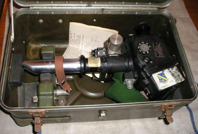
| Sextant |
? |
Kollsman Periscopic Sextant - The Periscopic Sextant system consists
of two sextants, the Kollsman Periscopic Sextant, the Kollsman Skylight
Compass, and a sextant mount. The sextant enables celestial body observations
for heading and position line determination, and the skylight compass enables
low altitude observations of the sun during twilight conditions and for
sunlight observations for heading determination only.
Photo of unit in carrying
case. (Photo via Epier.com) |
| ? |
? |
Night Vision Goggles |
| ? |
? |
Binoculars - gyrostabilized |

