| TACTICAL |
| |
|
| AN/AQS-4C |
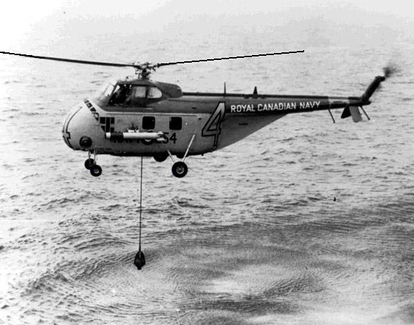
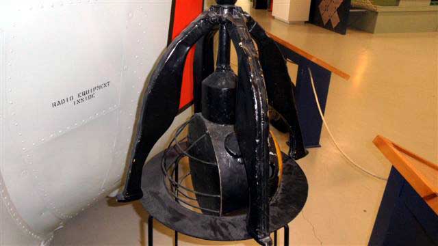
This airborne sonar type, introduced into service in the
1950's, was specifically designed for use by helicopters. It was also known
as dipping or dunking sonar. The transducer was enclosed in a small spherical
dome that was free flooding. Mounted in the dome was a special type of
compass called a flux valve that indicated the true bearing of the transducer
on an indicator mounted in the helicopter. The transducer could be manually
trained in either direction or automatically clockwise. An operator could
select one of three operating frequencies by selecting a screwdriver operated
switch on the front panel of the sonar transmitter/receiver. (Need photo
and more info). |
| AN/APX-25 (SIF) |
IFF (SIF) L-band IFF transponder. Range: 800-1300
MHz, output 1 KW pulse.
SIF panel (Courtesy Old Cockpit
Panels) |
|
|
| COMMUNICATIONS |
| |
|
| AN/ARC-27A |
UHF radio set. Consists of RT-178/ARC-27 UHF aircraft
receiver-transmitter. Frequency Range 225-399.9 MHz; Modes: MCW/Phone;
Power output: 9 watts; 18 preset frequencies on any one of 1750 frequency
channels. Transmitter may be tone modulated at 1020 Hz for emergency or
direction finding purposes. One guard channel in the 238- 249 MHz range
can be simultaneously monitored.
AN/ARC-27 exterior view. (Photo
courtesy: www.Radiosamling.dk)
AN/ARC-27 interior view. (Courtesy
Fair Radio Sales) |
| AN/AIC-4 |
Intercom amplifier and radio input control. |
| ? |
HF Radio?? . The photo at the bottom of this document shows a mast
for a wire HF antenna. Might be for an AN/URC-13. To confirm, contact:
Jerry.Proc@sympatico.ca |
| ? |
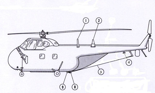
VHF Radio ??- Not sure if it was part of the Comm suite
on the HO4S-3. Photos of RCN HO4S-3's show a VHF mast on the tail boom.
(Item 1 in pictorial below) |
| NAVIGATION |
|
|
| AN/ARA-41 |
L.F. Radio Compass (Need photo and info) . It appears from
circumstantial evidence, that AN/ARD-7, AN/ARN-41, AN/ARN-42 and AN/ARN-54
radio compasses comprised from different combinations of about two
sets of components. |
| AN/APN-1 |
Radio altimeter; 420-460 MHz, Doppler frequency shift,
dual scale meter 0-400 and 0-4000 feet. Minimum height that can be measured
is 5 feet.
APN-1 Tx/Rx only. (Photo courtesy
Kurrajong Radio Museum)
APN-1 system components - (Courtesy
Tpub.com) |
| |
|
| OTHER |
|
|
| C-2A |
Compass |
