 |
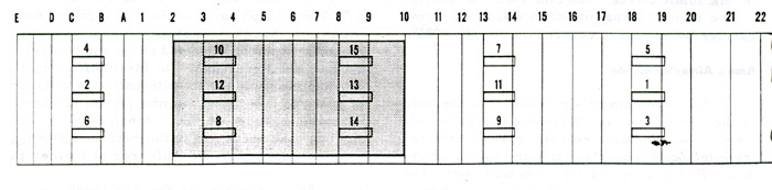
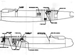
| Location of bomb carrier housings. Numerous bomb loading positions for various types and weights of bombs are illustrated in the manual The limiting factors in bomb loading are space and bomb size. (From the Lancaster Engineering Manual) |
CANADIAN LANCASTER - 10MR and MP ARMAMENT
BOMB GEAR
Provision is made on 10S and 10MR aircraft for the carriage of small bomb containers, mines and bombs from 250 lb to 4000 lb. in size. Six light series carriers can be installed in 10MR aircraft.
BOMB COMPARTMENT
The bomb compartment consists of the lower part of the fuselage between formers E and 22 as shown in the illustration below. The shaded area represents the long range fuel tank in the bomb compartment therefore no ordnance can be mounted in the shaded area when the auxiliary tank is in place. The housings are numbered 1 to 15 with the numbers being marked above and below the bomb floor to facilitate identification during loading operations.
|
| Location of bomb carrier housings. Numerous bomb loading positions for various types and weights of bombs are illustrated in the manual The limiting factors in bomb loading are space and bomb size. (From the Lancaster Engineering Manual) |
Bomb Carrier HousingsThe bomb carrier housings are mounted in the main floor over the bomb compartment and provide a means of locking the bomb carriers rigidly in position. They also serve as the circuit connecting link between the bomb aimer's panel and the bomb fuzing and release units.
Bomb Carriers
Bomb carriers of the following types may be accommodated in Lancaster X aircraft:
(a) Avro standard carrier Mk 1.
(b) Avro standard carrier Mk 2.
(c) Avro standard carrier Mk 2N.
(d) 2000 lb carrier, special for Lancaster
(e) Light series carrier Mk 3.Bomb Aimer's Position
The bomb aimer's position is in the nose of the aircraft. Control of the bomb release gear is effected from the bomb aimer's panel shown below.
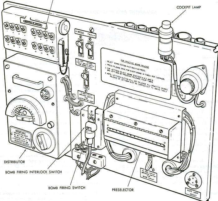 |
Bomb Aimer's Panel located on the starboard side. The switches in the upper left corner selected individual bombs or salvoes. Click to enlarge. (From Lancaster Engineering Manual) |
Bomb SightsProvision is made for the installation of a TIA bombsight on a universal sighting head mounted at the forward end of the bomb aimer's station. The TIA bombsight is the American version of the British Mark XIVA. The two sights are functionally identical and differ little except the method of construction.
On 10MR aircraft, provision is made for the alternate installation of a Mk III low level bombsight on the same mounting bracket as the TIA bombsight. The sighting head not in use, is mounted on a stowage bracket attached to the bulkhead at former E. The computer for the TIA bombsight is installed on the left side of the nose compartment and the computer for the Mk III low level bombsight is mounted on the right side of the fuselage, near the roof at the co-pilot's position.
Frazer-Nash, hydraulically operated gun turrets, are installed in the front and rear gun positions on 10MR aircraft. The front turret is armed with two Browning .303 calibre machine guns and four identical weapons are mounted in the rear turret.Provision is made in the front turret for two ammunition containers to be fitted - one at each side of the turret rotation ring. The containers, being mounted on the rotation ring, move with the rotation of the turret thus stabilizing the ammunition feed belt lengths.
Ammunition for the rear turret is supplied from four ammunition containers. Two are mounted at each side of the fuselage in the rear section. Each container accommodates 1900 rounds of ammunition. Ducts leading to the guns hold a further 600 rounds, making a total of 2,500 rounds available for each gun.
The ammunition belts, made up in 100 round lengths to facilitate loading, are fed into the boxes with the bullet noses pointing outboard. The belts for the left-hand guns must be placed in the boxes with a double loop end leading, while the belts for the right-hand guns should have a single loop end leading. When the boxes are filled, the belts for the left-hand guns will terminate in a single loop while the belts for the right-hand guns will terminate in a double loop.
 |
| Location of ammo boxes and ducts for the tail guns. (From Lancaster Engineering Manual) |
Frequent checks of the ammunition ducts had to be made to ensure that correct alignment was maintained between the separate lengths of duct and between the ducts and the ammunition boxes.The entry to each duct is flared to prevent the ammunition from fouling when the aircraft is banking, but if the alignment between any duct and box is found to be incorrect, the box must be moved until correct alignment is obtained and held in this position by the insertion of packing pieces.
Ammunition ducts must never be oiled or greased, otherwise grit and dirt will adhere to their surfaces and impede the passage of the ammunition. The spindles of the feed rollers at the end of the ducts had to be oiled sparingly. Care was taken when lubricating the spindles to ensure that no oil was allowed to drop onto the ducts.
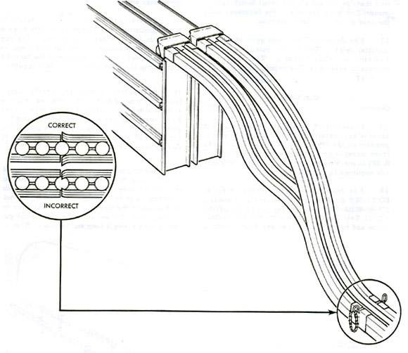 |
How the joint should look between lengths of ammo duct. Click to enlarge. (From Lancaster Engineering Manual) |
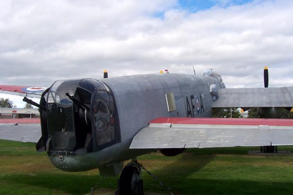 |
| Lancaster tail guns. (Photo by Ian MacCorquodale, Mac's Naval Photography) |
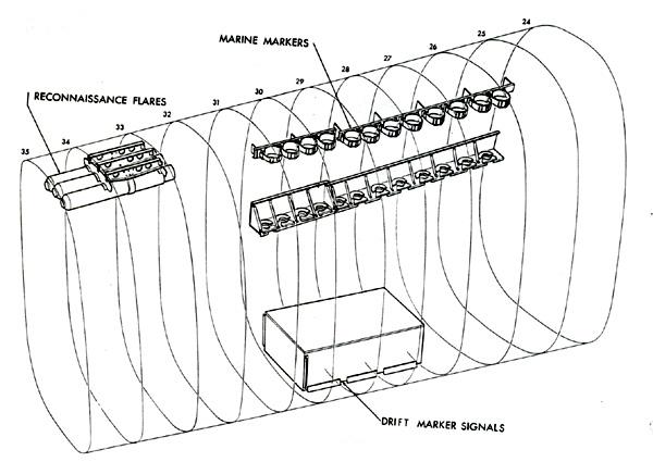
PYROTECHICS STOWAGES
 |
Pyrotechnics Stowages- pre mod 723.Click to enlarge. (From the Lancaster Engineering Manual) |
 |
|
| More pyrotechnics stowages. | |
Credits and References:1) Unless otherwise noted, all images are extracts from the Lancaster Engineering Manual EO 05-25A-2.
2) Leo Pettipas <lpettip(at)mts.net> Associate Air Force Historian. Air Force Heritage and History 1 Canadian Air Division.
Winnipeg, Manitoba.
3) Mac's Naval Photography http://macsnavylinks.ca/whatsnew.html
Dev 1/09