 |
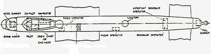
| 10 MR and MP crew positions. |
CANADIAN LANCASTER - 10MR and MP CREW POSITIONS
|
| 10 MR and MP crew positions. |
Click to enlarge
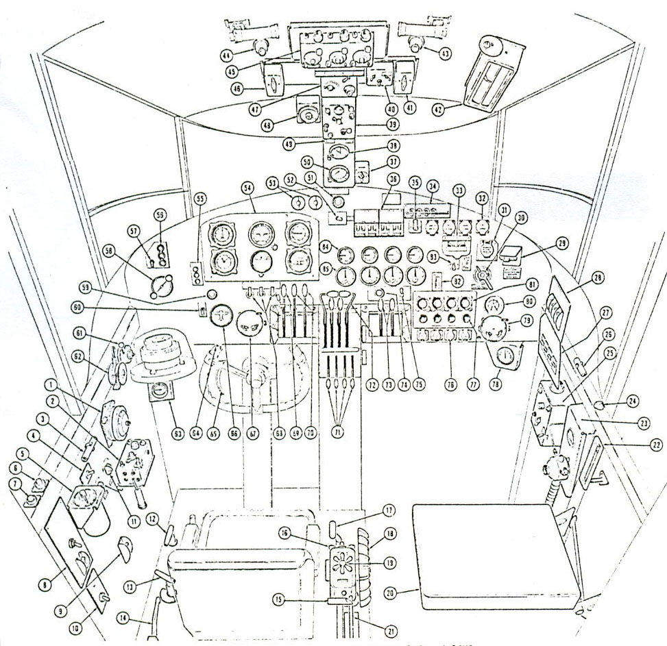 |
COCKPIT. The wartime 10S and the 10MR/MP variant are generally similar. The image only shows one control yoke and no rudder pedals in the interest of simplicity |  |
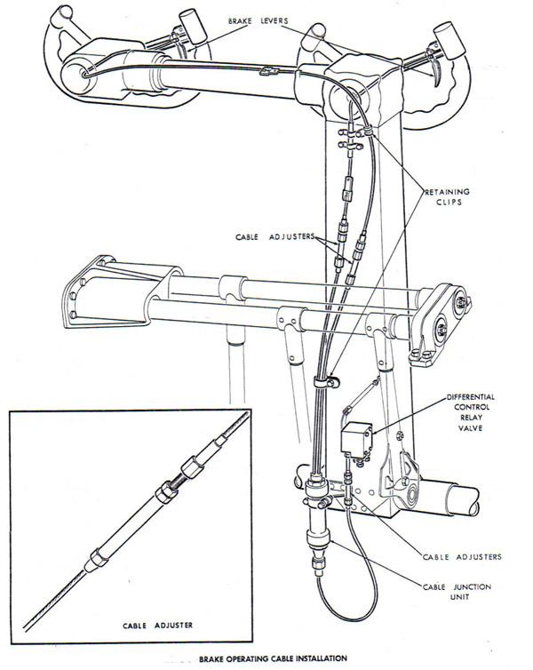 |
Detailed rear view of control yoke and brake cables. | |
 |
Internal view of co-pilot's control yoke. | |
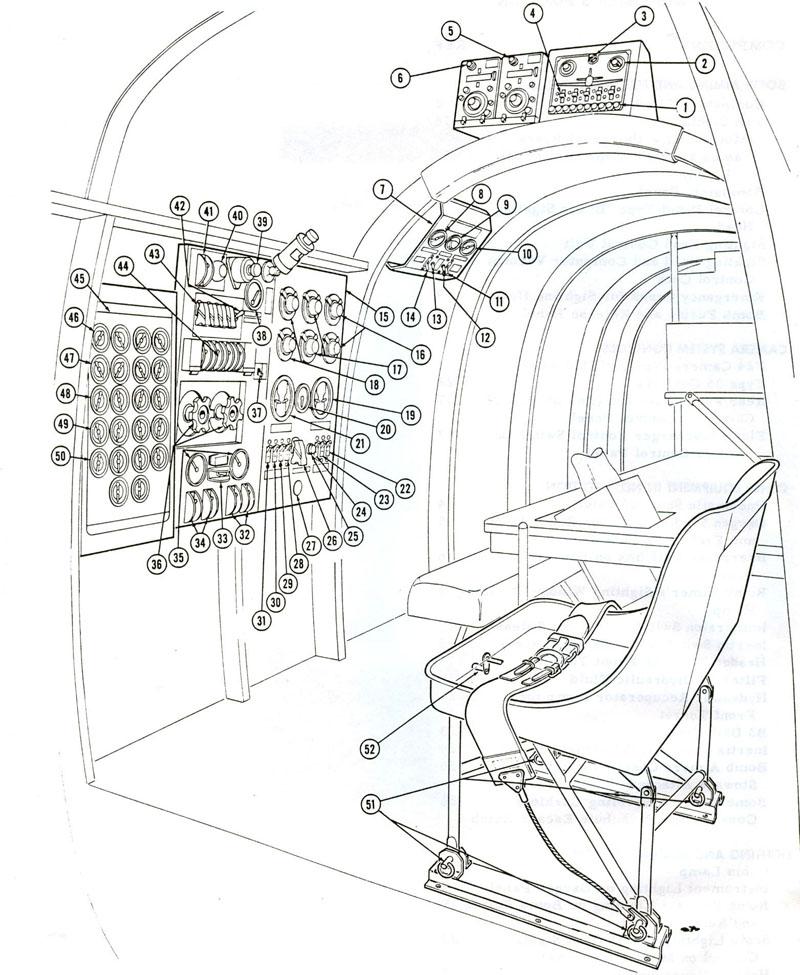 |
FLIGHT ENGINEER'S STATION. A simple layout when compared to other four engine piston aircraft which followed. | 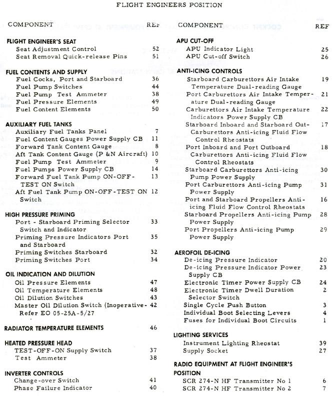 |
 |
BOMB AIMER'S STATION | 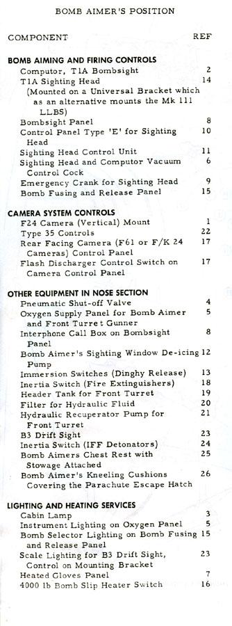 |
 |
NAVIGATOR'S STATION. This station is basically similar in all variants but different panels are used in each variant due to operational requirements. | 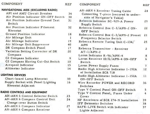 |
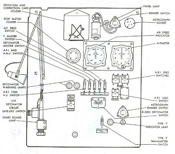 |
NAVIGATOR'S PANEL (10S). The 10MR/MP was similar. 10N and 10P are different. | |
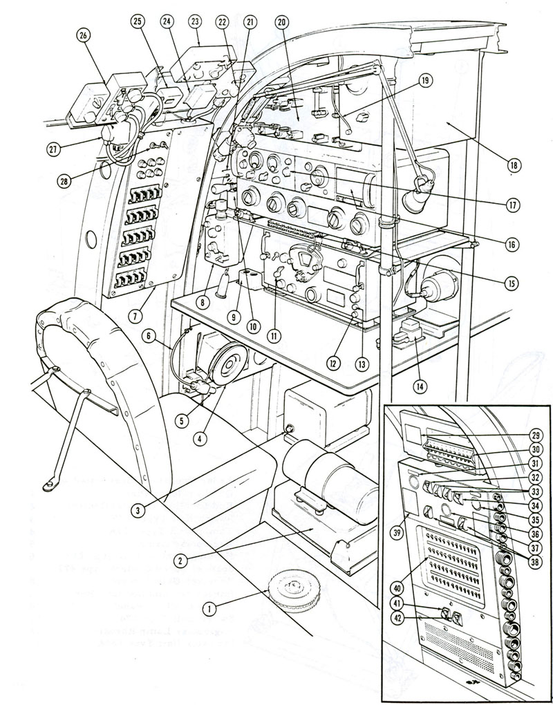 |
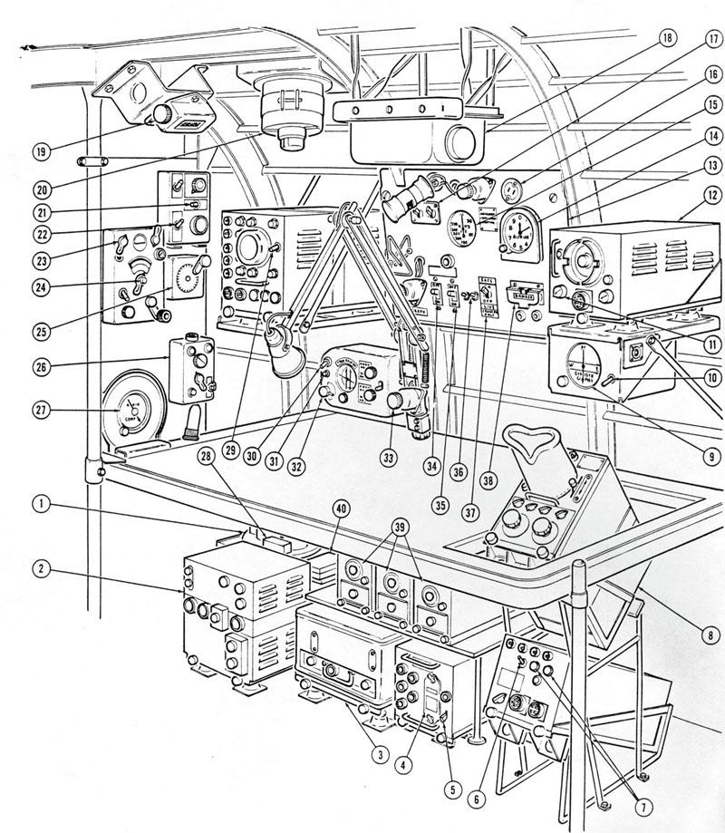
RADIO OPERATOR'S STATION | 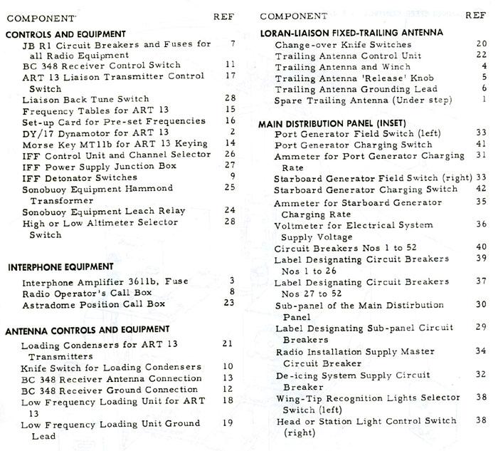 |
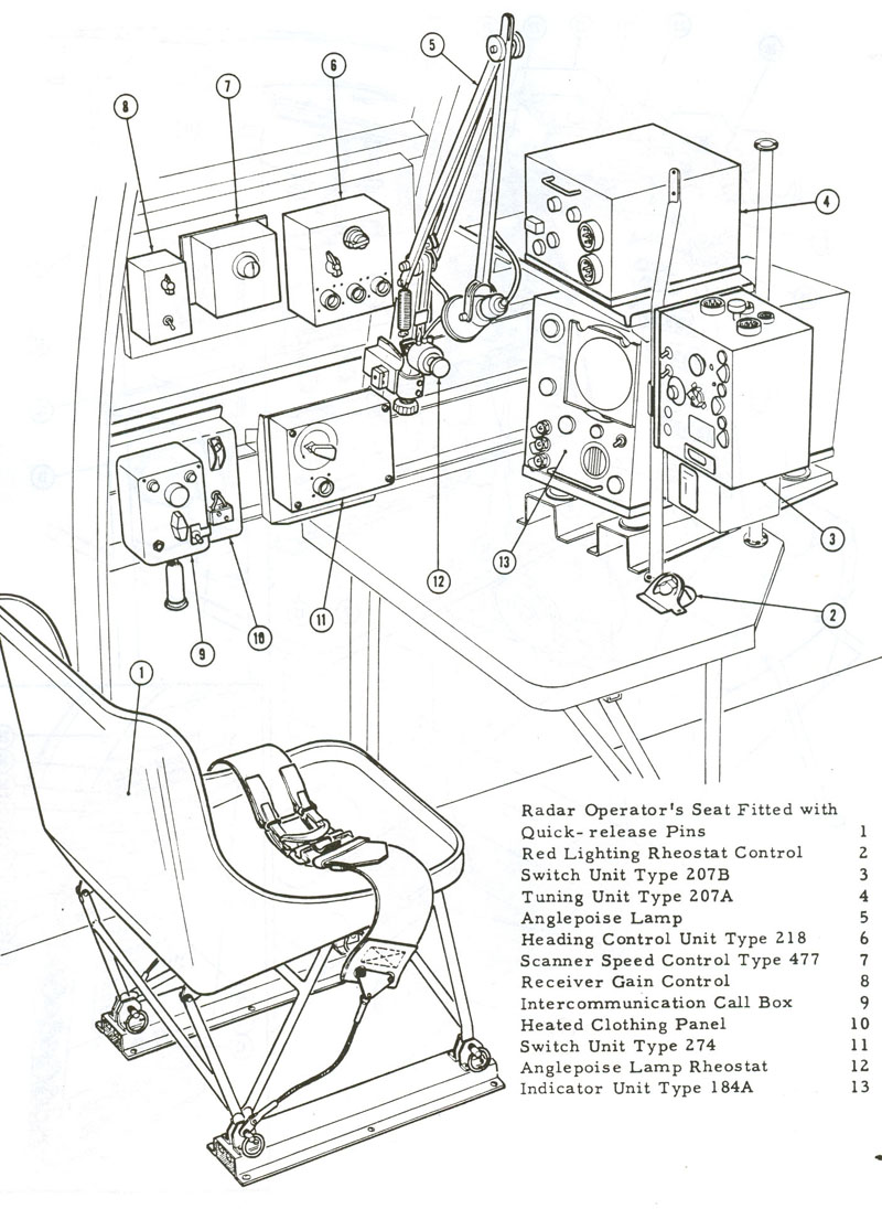 |
RADAR OPERATOR'S STATION | |
 |
SONOBUOY OPERATOR'S POSITION | 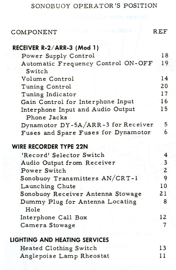 |
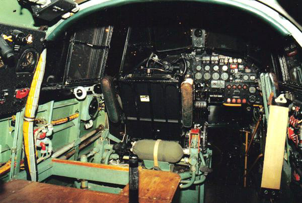 |
| This is a Lancaster cockpit display at the Canada Aviation Museum, Ottawa. The Navigator's station is behind the pilot's seat and the co-pilot's seat is in the folded position. It was hinged against the right side of the airframe and in the up position, it fastened to a bar next to the Landing gear selector. The back rest was also hinged on the right side. (Photo by John Phillips) |
Credits and References:1) Unless otherwise noted, all images are extracts from EO 05-25A-2.
2) Leo Pettipas <lpettip(at)mts.net> Associate Air Force Historian. Air Force Heritage and History 1 Canadian Air Division.
Winnipeg, Manitoba.
3) John Phillips <johnph(at)xplornet.com>
Oct 17/09