 |
| A complete sonobuoy system: ARR-3 receiver Mod 1 and the CRT-1 sonobuoy. (Graphic courtesy USN Library Department) |
The AN/CRT-1, designated as ERSB (Expendable Radio SonoBuoy), was used for the detection of submerged submarines. It consisted of a floating, cylindrical, waterproof cardboard container, incorporating a non-directional hydrophone suspended on a 20-ft. line below the buoy itself. Inside, was a frequency modulated radio transmitter for transmitting the underwater sounds received by the hydrophone to a receiver (AN/ARR-3 Mod 1) in the aircraft. The buoy transmitted on one of four frequencies in the range of 67 to 72 MHz. and had a lifetime of about 3 hours before self-scuttling.
 |
| A complete sonobuoy system: ARR-3 receiver Mod 1 and the CRT-1 sonobuoy. (Graphic courtesy USN Library Department) |
The radio range was approximately 10 miles when the aircraft was at 300 feet. The underwater range is equivalent to that of any good underwater sound system which may vary from 200 to 3,000 yards depending on the water conditions. No information was provided on the direction of the submarine.Each buoy weighed 14 lbs. The size of the buoy enclosure was 6" x 6" x 48". In normal operations one, or preferably two men were required to launch the buoy and to listen on the receiver. The power source for the buoy itself consisted of four 1.5 V "A" batteries, and two 67.5 V "B" batteries. The 35 pound sono-buoy receiver operated from a 24 VDC dynamometer and drew 70 watts.
Left: In the water and deployed. Right: The CRT-1 hydrophone internal view. It is a cylindrical magnetostriction unit that is wound on a nickel shell. Its construction permits the storing of the cable inside the hollow shell and effects a reduction in length of about 4 inches compared with earlier models. (USN pictorial via HNSA)
 |
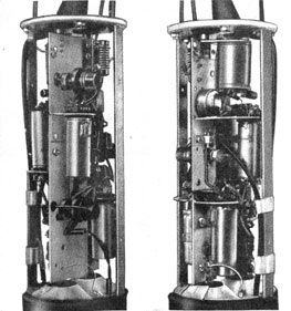
| CRT-1 internal view. The RF side is shown at the left and the AF side at the right. (USN pictorial via HNSA) |
The AN/CRT-1A transmitter is mounted on a single rectangular plate, with the audio amplifier and the reactance tube on one side and the RF circuit on the other. The mounting provides compactness and improved isolation between the AF and RF circuits. The bottom of the housing terminates in a cast-metal ring, which aids in stabilizing the buoy in the water and which provides a mounting for the hydrophone release mechanism. This mechanism consists of a spring arrangement, which holds the hydrophone firmly in place during shipping and handling but which automatically triggers on impact with the water and permits the hydrophone to drop to the limit of its 24-foot cable
 |
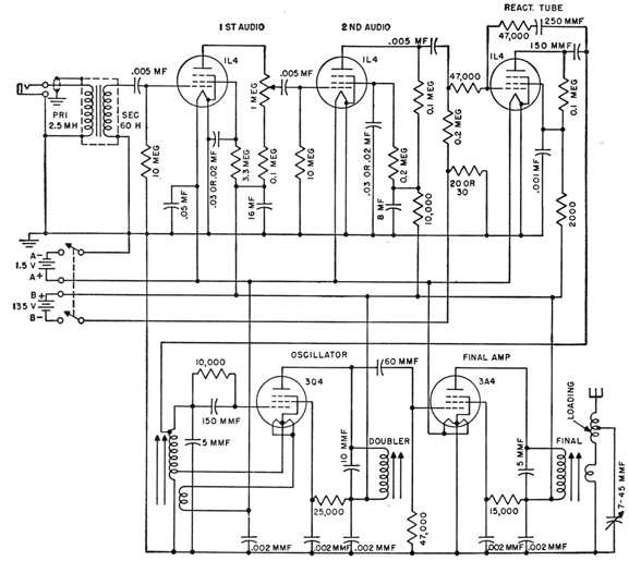
| AN/CRT-1 schematic. (USN pictorial via HNSA) |
The FM transmitter utilizes five vacuum tubes, which provide approximately 90 db of audio-voltage gain and an effective r-f antenna radiation of about 0.1 watt. Frequency modulation was used in preference to amplitude modulation for three main reasons: (1) the signal-to-noise ratio, which is considered of vital importance because the receivers are always used in close proximity to aircraft engines, is better for frequency modulation; (2) frequency modulation provides precise automatic control of volume of all signals sufficiently strong to fall within the effective operating range of the receiver; and (3) frequency modulation reduces the effects of interference between two buoys of the same frequency. This interference exists when extra buoys are dropped while tracking, and before the original buoys have ceased operating.
Credits and References:1) USN Library Department. CRT-1 http://www.history.navy.mil/library/online/radar-14.htm
2) AN/CRT-1 description http://www.hnsa.org/doc/sonar/chap16.htm