CANADIAN LANCASTER - MK X (10MR and MP)
ELECTRONICS SUITE
THE LANCASTER'S ELECTRICAL SYSTEM
This section summarizes the electrical installation and the
positions of the main electrical power sources and components in the Lancaster
aircraft.
The system consists of four, engine driven generators connected in parallel
and two 12 volt batteries in series supplying a positive feed to a number
of panels, distribution boxes and junction boxes. There is also a grounded
negative network of eight master grounding wires which ground separate
groups of services. The wiring between components is mainly sheathed in
flexible conduit or metal braided cables. Identification numbers on conduits
for general services are prefixed with the letters F for fuselage, P for
port mainplane and S for starboard mainplane.
DC Power Supply and Distribution
DC power is supplied from four engine driven generators which charge
two 12 volt 88 ampere hour batteries connected in series, the sum
of which provides a 24 volt, 88 ampere hour supply for the general
services. One, type "KX", self excited, four-pole, shunt-wound generator
is mounted on each inboard engine and one, type "UO", dual purpose generator
is mounted on each outboard engine. The type KX generators have full-load
outputs of 29 volts at 60 amperes. Current control is provided by type
F voltage regulators and type D cut-outs, mounted in the base of the main
distribution panel, which also regulates the output at 28 VDC +/- 0.5 volts.
The type UO generator is a dual purpose device supplying both AC and DC
outputs. Full load DC output for each is 30 volts at 100 amperes. Output
voltage is controlled at 28 VDC +/- 0.5 volts by carbon pile regulators
acting on the shunt field winding of the DC section of the generator.
Generator field switches and circuit breakers for the charging circuits
are provided. Those for the type KX generators are on the main distribution
panel and those for the UO generators on the Martin turret panel. At the
front of each engine fireproof bulkhead, connected in series with the generator,
is a noise suppressor to reduce the level of radio interference.
On the starboard side of the fuselage, mounted between the spars,
is a main electrical switch which permits the selection of power supply
to the aircraft services from either the aircraft's batteries or an external
power source. When the switch is in the "GROUND" position, the aircraft
supply is disconnected and power must be supplied from external batteries
or an external generator. When the switch is in the FLIGHT position, all
services are energized from the aircraft's electrical supply. When in this
position, the generators may be isolated by means of the field switches.
Main Distribution Panel
The main distribution panel is mounted on the starboard side of the
fuselage immediately forward of the front spar. The interior of the panel
serves as a main distribution junction box and contains 52 general service
isolating circuit breakers. The following components are mounted on the
panel:
* Two ammeters to register charging rates of inboard engine generators.
* Two inboard generator field switches.
* Two circuit breakers for KX generator charging circuit.
* One de-icing master switch.
* One radio master circuit breaker.
* One battery voltage indicator.
* One wing tip recognition light selector switch.
* One head or station light selector switch.
* 52 general service circuit breakers.
* Automatic cut-outs and voltage regulators for the KX generators.
Nine general service boxes are installed in the aircraft and are identified
by the prefix JB.
1200 Cycle AC Power Supply
Alternating current is supplied for the operation of specialized equipment.
This supply is provided by the AC sections of the UO type generators mounted
on the outboard engines. Full load output of the alternators is 80 volts
at 15 amperes at a frequency of 1200 to 2400 cycles with the nominal
frequency being 1,200 cycles per second at 3000 (generator) rpm. Power
from this alternator is supplied to an alternator plug panel mounted on
the port bulkhead forward of the navigator's table.
400 Cycle AC Supply
Two Jack & Heintz F16 inverters are fitted on the starboard side
of the fuselage between formers 9 and 10. No. 1 inverter is mounted on
the fuselage floor and No 2 is attached to the fuselage structure immediately
above No.1. Each inverter is capable of providing 115 VAC, 400 cycle,
250 VA when operated on an input of 26 to 29 VDC. A cautionary note on
the inverters instructed the user not to use them continuously. Alternate
selection between the two inverters should be made at regular intervals.
In practice, this was not followed because the Navigation section complained
about power interruption to their B3 drift meters when the inverters were
cycled.
AUXILIARY POWER UNIT (APU)
The APU is installed on the starboard side of the aircraft and is attached
to two top-hat section stringers which are bolted to the upper flanges
of the tailplane spars. The APU uses a single cylinder, air cooled, two-stroke
engine driving a generator which is connected to the engine's crankshaft.
Charging output is at 27 volts at 87.7 amperes DC for all ground running
purposes. A control box at the forward end of the APU incorporates a voltmeter
and an equalizing switch.
EXTERNAL POWER SOURCE
During ground servicing operations, power may be supplied to the aircraft
services from an external source. A socket type connector is installed
in each inboard nacelle to connect the aircraft services to an external
battery or portable generator supply. Two types of connector sockets are
used; that in the port nacelle being of the British two prong type. An
American style three prong AN type socket is installed in the starboard
nacelle. This arrangement permits the use of either British or American
type ground equipment.
Click to enlarge
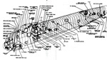 |
Location of 10MR electrical equipment. (Extract
from EO 05-25A-2) |
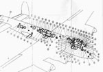
 |
The 10MR's electrical grounding system. (Extract
from EO 05-25A-2) |
 |
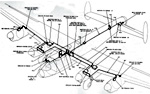
Lancaster antennas. This configuration was likely
applicble to the MP or MR Lancaster variants. (Extract from
EO 05-25A-2) |
DESCRIPTION OF ELECTRONICS
Variants
10S = Standard version
10MR = Maritime Reconnaissance
10MP = Maritime Patrol
10N = Navigation Trainer
10P = Photographic Reconnaissance
| TACTICAL |
|
|
|
| DEVICE |
USED ON |
DESCRIPTION |
| |
|
|
| H2S Mk 2D |
MR, S |
WWII era search radar. Initially it operated in the
10 cm band using the CV64 magnetron but in later versions the wavelength
was first reduced to 3 cm and then to 1.5 cm. Its service life spanned
from 1943 to the 1990's. Mk 2D, the one installed in the 10MR operated
on a wavelength of 9.1 cm. The 10MR Lancs only used the 10 cm version. |
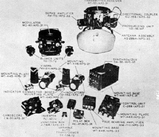
| AN/APS-33 |
MP |
X-Band Search Radar. It replaced H2S radar in the 10MP
variant. Transmitter: 9,375 MHz plus or minus 55 MHz. Peak RF Power Output:
52 kw minimum. Range up to 200 nm. Uses the AS-289A/APS-33 antenna whose
dome was like a 20 gallon cylindrical drum tank hanging straight down from
the fuselage.
It came in five variants: AN/APS-33 (Type I) ; AN/APS-33A (Type II);
AN/APS-33C (Type III); AN/APS-33D (Type IV); AN/APS-33F (Type V).
It is not known at this time as to which variant was fitted on the 10MP
Lancaster but likely it was the first type. The APS-33 dome did not retract.
AN/APS-33 system components (Courtesy
Tpub.com) |
| AN/UPD-501 |
MP |
High Probability Radar Early Warning directional finding
receiver. Fitted towards the end of the Lanc's service life. See receiver/display
photo below table. |
| AN/CRT-1 |
MR/MP |
Sonobuoy system. |
| AN/ASR-3 |
MR/MP |
Diesel submarine exhaust gas detection system, nicknamed
Sniffer. The sensor is based on technology developed by the Royal Navy
during WWII and had a fairly short detection range. Nonetheless, it was
surprisingly valuable up until the 1980s. Many airborne naval radars lacked
the definition to pick up a snorkel (especially in rough seas) so it was
entirely possible to fly right over a snorkeling sub, especially at night. |
| SCR-695 |
MR/MP |
IFF Set, Mark III operating on the I and G-Bands.
See detailed explanation elsewhere in this document. |
| Model 22N |
MR/MP |
Pierce Wire recorder. Used to preserve proof of detection
and kill when used in conjunction with the sonobuoy receiver. It recorded
the output of the sonobuoy receiver and the interphone conversations. |
|
|
|
| COMMUNICATIONS |
|
|
|
| DEVICE |
USED ON |
DESCRIPTION |
| |
|
|
| BC-348 |
MR/MP |
HF "Liason" receiver. Frequency coverage 190
- 500 KHz and 1.5 to 18 MHz. This receiver could only be controlled locally.
Requires 28 VDC, 56 watts. See photo below table. |
| ART-13 |
MR/MP |
Collins autotune HF transmitter used for Liason communications.
Frequency range 1.5 to 18 MHz and 200 to 600 KHz . Modes: CW, MCW and AM.
It has ten autotuned preset channels on HF and one on LF. Power output
varies between 65 and 90 watts depending on frequency. Input power 780
watts. The transmitter is coupled to the trailing wire antenna by a CU-25
antenna loading unit. See Radio Ops position photo below table. |
| SCR-274N |
MR/MP |
HF "Command" transmitter/receiver radio system. Click on
link for photos and a more detailed explanation. |
| SCR-522 |
MR/MP |
The SCR-522 was a voice only, VHF transmitter/receiver
operating in the 100 to 156 MHz band with a power input of 8 to 9 watts.
Operation was provided on any one of four crystal controlled channels.
Integrally mounted in a common case, was the BC-624A VHF receiver and the
BC- 625A VHF transmitter. The rest of the system consisted of 28 VDC input
dynamotor (PE-94-A) and various jack and junction boxes. Input power consumption
was 311 watts. Remote control of the radio is provided by a channel selector
box located in the cockpit. The SCR-522 is also duplicated for redundancy
in the 10MR and 10MP.
External view of SCR-522 with pilot's
remote control box.
(Photo by Jerry Proc)
Internal view of SCR-522
sitting atop its case.
(Photo by Jerry Proc) |
| 3611B |
MR/MP |
Interphone Amplifier. A two-stage, high gain amplifier
which provides interphone facilities for all crew members. It supports
the use of carbon or dynamic microphones. Output power is 3 watts. |
| MI-22A |
MR/MP |
Station box. These provided simultaneous communications facilities
for all crew members. Individual crew members employed the desired system
without interference from one another except when CALL was used. This would
override all services. |
| RL-42 |
MR/MP |
HF Trailing Wire Antenna. The trailing wire antenna winch RL-42 was
controlled from a reel control box BC-461. Contained on the reel was 290
feet of wire connected through a fairlead to a five pound lead weight.
Every turn of the reel represented 1 foot of antenna. A counter, connected
to the reel, indicated how many feet of wire were extended. A changeover
switch allowed the trailing wire antenna to be shared between the
Loran navigation set and the ART13/BC348 Liaison radio.
Drive motor and reel. (Photo courtesy
Consolidated Aircraft, circa 1943) |
|
|
|
| NAVIGATION |
|
|
|
| DEVICE |
USED ON |
DESCRIPTION |
|
|
|
| SCR-718 |
MR/MP,
10N, 10P |
Radar Altimeter (High). 50
ft. to 40,000 ft. Accuracy ± 50 ft. plus 0.25%. Operates on
420-450 MHz. Consists of a BC-788-A transmitter-receiver, I-152-C indicator
calibrated directly in feet and the AT-4/ARN-1 antenna. Transmitting
and receiving antennas used by this equipment are also part of the low
altimeter system. Operates on primary power source of 115 VAC. Power consumption
of the radio set is 135 watts. Circa 1943.
System components (Courtesy History.Navy.com) |
| AN/APN-1 |
MR/MP,
10N, 10P |
Radar Altimeter (Low). Ranges:
0-400 and 0-4,000 feet. Operates on 420-460 MHz. Uses Doppler frequency
shift. Circa 1943. Consists of a transmitter/receiver RT-7/ARN-1, altitude
indicator ID-14/APN-1, altitude limit switch SA-1/APN-1, antenna assembly
AT-4/APN-1, antenna relay type RCA-AVA/68 and a dummy plug. Power input
75 watts.
The altitude indicator incorporates a shutter device to control the
double range dial of 0-400 feet and 0-4000 feet. The limit switch determines
the altitude at which the limit indicator operates, with the scale calibrated
directly in feet on the low range and multiplied by ten on the high range.
Three lights, green, red and amber, comprising the limit indicator, illuminate
and indicate the relative altitude of the aircraft with respect to the
setting of the limit switch.
The antennas used with the low altimeter are also part of the high altimeter
system. The assembly consists of two dipole antennas, located on the under-surface
of the wings between the inboard engines and the fuselage. The antenna
relay, RCA-AVA/6B, which transfers the antennas to the required system,
is controlled by switch mounted on JBR No 1.
APN-1 Tx/Rx only. (Photo courtesy Kurrajong
Radio Museum)
APN-1 system components (Courtesy
T-pub.com) |
| AN/APN-4 |
MR/MP,
10N |
The AN/APN-4 is an airborne Loran
'A' navigational aid employed to determine the geographical location of
the aircraft in relation to several ground based Loran-A stations.
This installation comprises a receiver (R-9A/APN-4) and an indicator
(ID-6/APN-4) The plotted data obtained from the indicator gives the location
in degrees of latitude and longitude. The receiver operates on four channels
preset at frequencies ranging from 1.6 to 3.3 MHz and 7.58 to 11.75
MHz. A channel selector is provided on the receiver for selection of the
desired frequency. The controls for the equipment are mounted on the front
panels of the indicator and receiver This equipment utilizes the liaison
fixed or trailing wire antennas. Maximum power draw is 270 VA.
Loran 'A' ID-6 display-only. (Photo
by Jerry Proc) |
| AN/APN-2 |
MR/MP, 10N, 10P |
The AN/APN-2 "REBECCA" is a blind
homing and approach aid used by the navigator to obtain the relative location
of a co-ordinated ground beacon stations. The system comprises a transmitter
-receiver, ATT1/APN-2, indicator, BX-929-A, control box, C-3/APN-2, remote
tuning unit, C-134/APN, tuning adaptor, MX-196/APN, two receiving dipole
antennae (AN148) and one transmitting whip antenna.
The transmitter-receiver unit transmits RF pulses to a ground station
and receives an answering pulse. The received signal appears on the cathode-ray
tube display of the indicator as a visual representation of the distance
and direction of the answering station in reference to the line of flight.
The receiver operated on two pre-set frequencies spaced by 5 MHz in the
range of 214 to 234 MHz.
The transmitter operated on five pre-set channels at frequencies of
214, 219, 224, 229 and 234 MHz.. An antenna filter, type F-65-A, is connected
in the transmitter antenna co-axial feeder to prevent interference with
the IFF system.
This equipment operated from the aircraft's primary 28 VDC and
80 VAC power mains; the total power requirement was 25 watts and 180 VA
respectively.
BC929 indicator unit. (PE1NGZ
Signals Collection '40-'45)
AN148 antenna (PE1NGZ Signals
Collection '40-'45) |
| AN/ARD-3 |
MR/MP |
Direction finding set. Manufactured by Collins. Circa 1944.
Need photo. |
| MN-53B |
MR/MP |
Marker receiver. Made by Bendix Radio, Baltimore. Used
to receive a beacon signal on 75 MHz. It provided aural and visual identification
of airways, outer or inner markers, each of which had its own distinguishing
modulation tone of 3,000, 400 or 1,300 Hz respectively. |
| AN/ARN-6 |
MR/MP |
Radio Compass. 150 to 1750 KHz. Being dual controlled,
it could be operated by the pilot or navigator. |
|
|
|
| OTHER |
| |
|
|
| AN/ASA-3 |
MR/MP |
Static Discharger. They were provided to reduce radio interference
caused by the accumulation of static electricity on the aircraft structure.
The discharger consists of a 13 inch conducting cotton wick enclosed in
a plastic sheath. One and a half inches of the wick extend from the open
end of the sheath. The other end is enclosed in a metallic tube which is
flattened on the end and provided with two mounting holes. Four dischargers
are mounted on the trailing edge of each wing and three are mounted on
the trailing edge of each rudder. |
| DR |
MR/MP |
Compass (British) |
| AMU, API and GPI |
MR/MP |
Ground and AP position indicators. |
| F.24 |
MR/MP |
The Williamson F.24 camera was a day/night camera
employing a 5" x 5" negative format. It was the main air reconnaissance
camera at the start of WWII and was available in 4, 5, 8 and 20 inch
focal lengths. Pictured in the link is a camera with an 8 inch focal length. |
ANTENNA SYSTEMS
 |
Antenna systems of the 10 MR and 10MP Lancaster.
Not shown are the static dischargers located on the wingtips. Click to
enlarge. (Extract from EO 05-25A-2) |
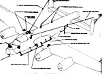
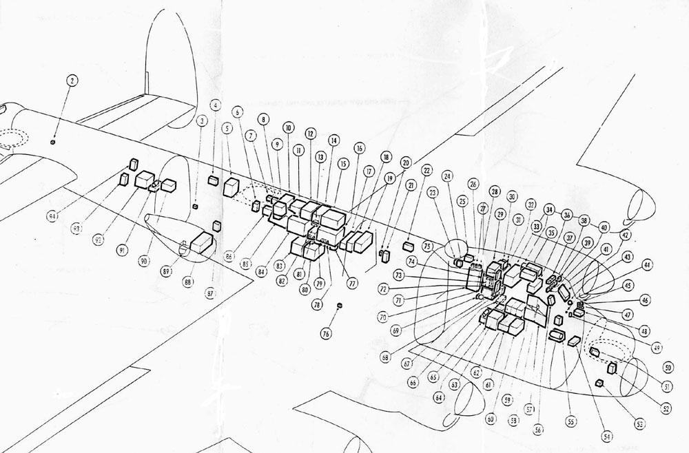
LOCATION AND IDENTIFICATION OF ELECTRONICS
 |
It has been said that the Argus (CP107) was a
flying electronics warehouse. The Lancaster MR/MP can certainly challenge
that distinction. Click either thumbnail to enlarge. (Extract from
EO 05-25A-2) |
 |
FEATURED EQUIPMENT
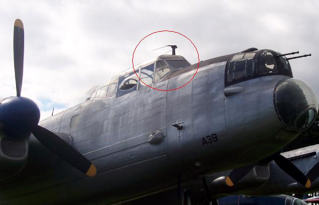
AN/APS-33 RADAR and AN/UPD501 ANTENNAS
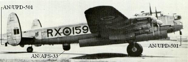 |
| The UPD-501 and APS-33 antennas show up well on RX-159, a 10MP variant.
(Photo
by Prestwick Hayden Hurst) |
ART-13 TRANSMITTER/BC-348 RECEIVER
 |
| A BC-348 receiver (bottom) and ART-13 transmitter (top) at the radio
operator's position of this Canadian-built Lancaster. (Photo from the
collection of Hu Filleul) |
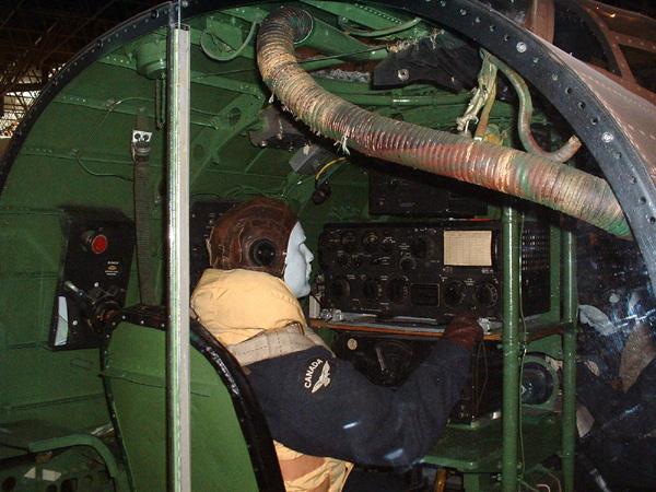 |
| This display of a Canadian Lancaster radio operator's station is
part of the collection of the Canada Aviation Museum, Ottawa, formerly
called the National Aeronautical Collection. (Photo by Jerry Proc) |
SCR-695 IFF
The SCR-695 is a Mark III IFF transponder. It receives challenge signals
from a ground station and transmits coded replies to identify the aircraft
as friendly. This installation comprises of a transponder, BC-966A, power
control box, BC-958A, selector control box, BC-965A, antenna assembly,
AN-950A, and a destructor system.
The transponder operates within the frequency range of 157 to 187 MHz
in the ' I ' band, and 194 to 211 MHz in the 'G' band. On the ' I ' band,
the transmitter is pre-set to permit the transmission of six differently
coded replies; the 'G' band replies are non-coded. Selection of any coded
transmission is made possible by the selector control box.
A power control box is provided with an EMERGENCY switch which is operated
when the aircraft is in distress. The EMERGENCY reply to any challenge
signal consists of a distinctive code, giving an immediate indication that
the aircraft is in difficulty. The phone jack on this unit permits the
use of headphones, to enable a rough check of the operation of the equipment.
The ON-OFF switch controls the input power to the dynamotor in the transponder.
An ON-OFF switch located on the pilot's auxiliary panel, and an EMERGENCY
'F' switch on the pilot's instrument panel provide the pilot with a remote
control of the equipment.
The destructor unit is an electrically operated detonator which will
destroy the transponder to the extent that it cannot be utilized by the
enemy. The destructor control system consists of an impact switch, isolating
switch, warning lights and three push-button type switches. The circuit
is energized by depressing the push-button switches on the navigator's
panel, at the radio operator's station or on the pilot's instrument panel.
The impact switch located on former G (fuselage structural member) , starboard
side, also energizes the detonator circuit when the SAFE-LIVE switch on
the navigator's panel is in the LIVE position.
AN/UPD-501
The UPD-501 was a High Probability Radar Early Warning directional finding
receiver which was used to detect radar emissions on the SHF radar bands
and gave some indication of the frequency in use, bearing, and the antenna
rotation period. It was introduced late in the service life of the Lancaster
MR.
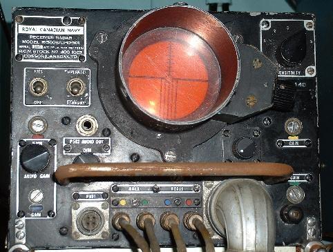 |
| AN/UPD-501 receiver. The system was made by Cossor Canada Ltd. (Photo
by Jerry Proc) |
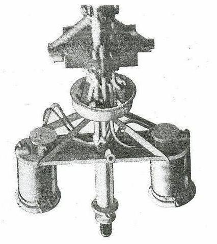 |
| Airborne version of the UPD-501 antenna with radome removed. (Photo
courtesy RCN) |
This device was the outcome of a project initiated by Naval
Headquarters, and was a contemporary of the early Magnetic Anomaly Detector
(MAD) work. It was a wide-band dual-band electronic countermeasures
(ECM) receiver system. This project was started in the early 1950s
by the National Research Council who undertook to develop "a simple instantaneous
direction-finding receiver-display for detection of non co-operative radar
transmissions expected to be of short duration". It was designed
to listen for radar emissions from submarines, surface vessels and even
aircraft.
AN/ASR-3
The AN/ASR-3 detected particulate matter from diesel exhaust. It took
in an air sample, analyzed it and gave a visual and aural indication. It
could be set for "sensitivity" and would produce an "in trail" and "out
of trail" mark that the crew would plot, then reverse course to re-enter
the trail gaining additional "marks." Eventually the navigator plotted
a rough course to the target.
Not only would it detect a snorting sub, it would also detect destroyers,
merchant ships, fishing boats, and the entire East or west coast of North
America. In other words, whatever value it had in open ocean conditions
was quickly lost as the aircraft approached crowded waters or pollution
filled urban areas.
AN/ARN-5 ILS SYSTEM
 |
| This Lancaster 10MP, held in the collection of the Greenwood Aviation
Museum, sports an antenna for the AN/ARN-5 Instrument Landing System
receiver. This device was not found in the Lancaster equipment manifest
so perhaps it was limited to aircraft which operated from bases which
had an ILS facility such as 408 Sqn. None of Lancasters in 2(M)OTU or 407
Sqn had them (Photo by Ian MacCorquodale, Mac's Naval Photography) |
AN/APN-2 "REBECCA/EUREKA"
Rebecca /Eureka was a simple system designed initially to assist with
the delivery of supplies to the Allied Armies or Resistance groups in occupied
Europe during WWII. Rebecca was the airborne portion while Eureka was the
ground based portion. The original system was effective only to within
two miles at which time the crew had to switch to visual means of locating
the drop zone. Reliance on Rebecca without visual confirmation invariably
resulted in premature drops as occurred during the American airborne landings
in Normandy. The system eventually expanded into blind homing and approach
aid for aircraft. The Rebecca code name was derived from the phrase "recognition
of beacons".
The ground based Eureka beacon complete with its aerial was air-dropped
and assembled on the drop zone. The Eureka transponder was
based on a super-regenerative receiver with a separate transmitter
tube and powered by a battery operated vibrator supply. A coding
unit which was part of the Eureka beacon provided an identification signal
and also permitted it to send simple Morse Code messages by periodically
varying the width of the beacon response pulses.
Airborne Rebecca equipment radiated 5 microsecond wide interrogating
pulses about 300 times a second.
on a single frequency. On receipt of the interrogating pulses, the
Eureka beacon located on the ground triggered its associated transmitter
causing responses to be radiated on a different frequency but at the same
pulse recurrence frequency of the interrogating transmitter. The returned
signal, received on both the right and left Rebecca receiver aerials, was
displayed on a cathode ray tube in which the time-base was synchronized
with the original pulse from the Rebecca transmitter and applied to the
Y-plates of the cathode ray tube. The received signals were switched into
the receiver in synchronism with the switching of the video-frequency output
signals to the right and left hand X-plates of the cathode ray tube. In
this way, if the beacon was to the right, the signal to the right of the
time base will have a greater amplitude, in which case a right turn will
be necessary to make the signals display equally in amplitude on either
side of the time. Then the aircraft will then be flying directly towards
the beacon.
Early models of the system were limited to a single frequency. Later
ones could switch between five frequencies.
Eureka Mk VII was a rack mounted, non-mobile transponder used at RAF
bases for aircraft to home onto.
The Mark X version of both Rebecca/Eureka worked in the 1000 MHz range.
This was developed for use during in-flight refueling, enabling the receiving
aircraft to locate the tanker while maintaining radio silence. The Tanker
aircraft carried the Eureka and the receiving aircraft carried the Rebecca.
This equipment was trialled in the early 1960's.
Credits and References:
1) Hu Filleul <hufilleul(at)shaw.ca>
2) Canadian Aircraft Since 1909. Molson and Taylor.
3) Leo Pettipas <lpettip(at)mts.net> Associate Air
Force Historian. Air Force Heritage and History 1 Canadian Air Division.
Winnipeg, Manitoba.
4) Lancaster engineering manual EO 05-25A-2 dated 30
August 1957
5) John Phillips <johnph(at)xplornet.com>
6) SCR-718 info: http://www.gordon.army.mil/ocos/museum/scrcomponents/scrPart4.asp#SCR-718
7) F24 camera. http://www.airrecce.co.uk/cameras/raf_ww2_cameras.html
8) PE1NGZ Signals Collection '40-'45
9) APN-2 info http://www.qsl.net/pe1ngz/airforce/airforce-raf/raf-eureka-rebecca.html
10) AN/ASR-3 info : http://www.harpoondatabases.com/encyclopedia/Entry1650.aspx
11) SCR-718 images. http://www.history.navy.mil/library/online/radar-12.htm
12) http://en.wikipedia.org/wiki/Eureka_beacon
13) http://www.qsl.net/pe1ngz/airforce/airforce-raf/raf-eureka-rebecca.html
14) http://www.duxfordradiosociety.org/equiphist/reb-eureka/reb-eureka-hist.html
15) Surplus Conversion Handbook by Tom Kneitel. Cowan
Publishing. 1964
16) SCR 695 http://www.gordon.army.mil/ocos/museum/scrcomponents/scrPart4.asp
17) Duke Dawe <dukegm(at)shaw.ca>
18) Mac's Naval Photography http://macsnavylinks.ca/whatsnew.html
Back to Lancaster Main Document
Nov 24/09


