CANADIAN LANCASTER - MK X
SOME ELECTRONICS FOUND IN OTHER VARIANTS
This information on other Lancaster variants
has been posted simply because it was available.
Lancaster Variant
10N- Navigation Trainer
10P - Photographic Reconnaissance
| NAVIGATION |
|
|
|
| DEVICE |
USED ON |
DESCRIPTION |
|
|
|
| AN/APN-3 |
10P |
SHORAN
is an acronym for SHOrt RAnge Navigation, a type of electronic navigation
and bombing system which uses a precision radar beacon. It requires the
AN/APN-3 receiver in the aircraft and two AN/CPN-2 or 2A ground stations.
A maximum range of 300 statute miles can be expected with a clear radio
path |
|
|
|
| OTHER |
| |
|
|
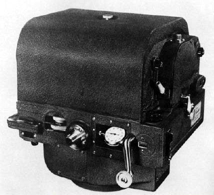
| Fairchild F224 |
10P |
Ordnance survey camera. Made from 1948 to 1956 by the Fairchild
Camera Company. Comes with a 6-inch f.6.3 Bausch and Lomb Metrogon single
lens. The format was 9 inch by 9 inch and the magazine could hold 250 exposures.
The K17B could be used in lieu of the F224.
F224 Camera (Image courtesy NOAA) |
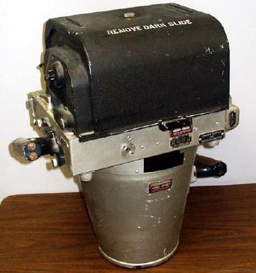
| K17B |
10P |
Ordnance survey camera. Made by the Fairchild Camera Company
from 1944 to 1949. It used a single lens and a 9 inch by 9 inch format.
The F224 could be used in lieu of the K17B.
K17 Camera (Image courtesy NOAA) |
| Model ? |
10P |
Tri-met cameras |
10N, 10P CREW STATIONS
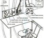 |
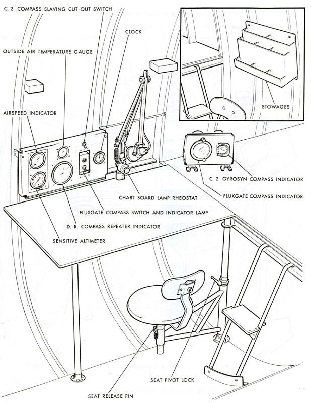
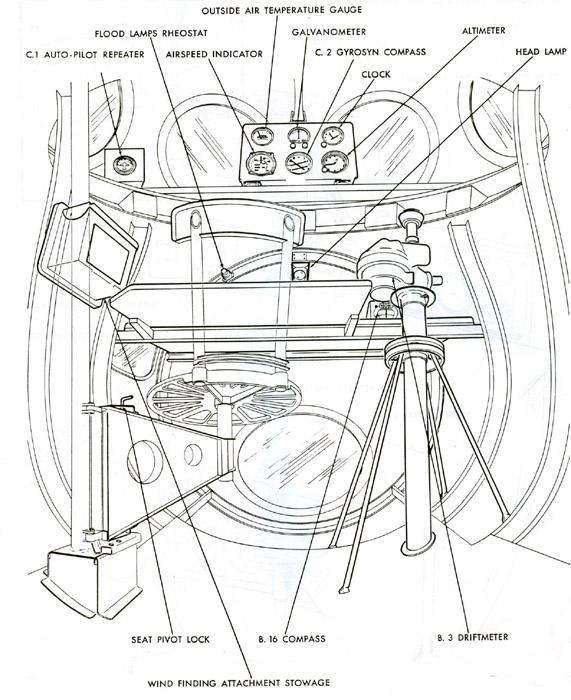
10N - Third Navigator's Station. It is
situated between formers 22 and 24. |
 |
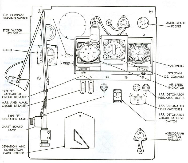
10N - Navigator's Panel |
 |
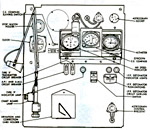
10P - First Navigator's Station. This is incorporated
into the nose section of the 10P. |
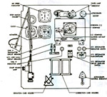 |
10P - Navigator's Panel |
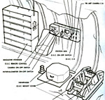 |
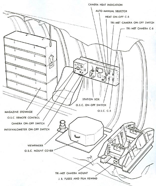
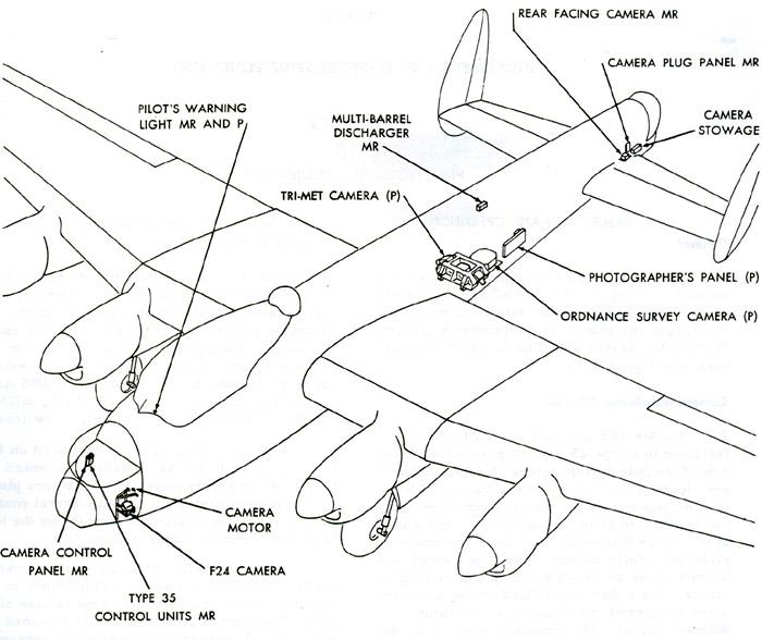
10P - Photographer's Station |
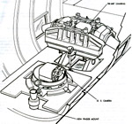 |
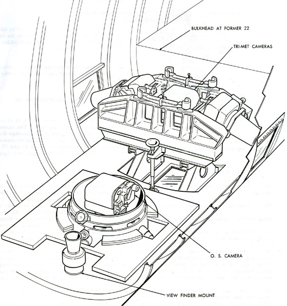
Tri-met and OS Camera Mountings. The tri-met
cameras pointed to starboard, port and down. |
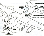 |
10P - Location of Photographic Equipment |
| Extracts from EO 05-25A-2 |
PHOTOGRAPHIC EQUIPMENT - 10S/MR/MP
Camera Installation 10S
On 10S aircraft, an F24 camera is installed in a type 25 mounting on
the left hand side of the nose section between formers E and F. The camera
rails are fitted into two brackets on the mounting structure, permitting
them to slide horizontally at right angles to the centre line of the fuselage.
The brackets slide vertically on mounting tubes which are braced to the
bulkhead at former E by tubular struts. Six holes are drilled in the mounting
tubes to permit installation of the camera at different heights. The camera
is mounted so that the optical axis is normal to the line of flight.
The camera motor is mounted at the top of the bulkhead at former E and
is connected to the camera by a Shakespeare cable. The camera itself is
controlled by a type 35 camera control mounted on the bomb aimer's port
panel. A camera heating panel is mounted below the bomb aimer's panel to
supply current to the heating elements of the camera muff and lens heater.
Camera Installation on 10MR
On 10MR aircraft, modification 658 Part A introduces a rear facing F24
camera installed on a type 25 mount between formers 39 and 40 in addition
to the original F24 camera in the nose section. Two type 35 camera controls,
one for the forward camera and one for the rear facing camera, are mounted
on a camera control panel on the right hand side of the nose section. A
camera switch panel, below the type 35 controls, carries a switch for the
rear facing camera heater muff.
Part B of modification 658 makes provision for the installation of various
types of real facing cameras for day or night operation. An automatic camera
control panel is mounted above the camera control panel. Incorporated in
the automatic camera control panel are preselectors, an automatic distributor,
BOMBS AND CAMERA selector switch, POWER, HEAT TEST, DISCHARGER and camera
switches
A camera plug panel is installed on the left hand side of the fuselage
forward of former 40 to supply power to the camera plug and the camera
heat plug. A multi-barrel photoflash cartridge discharger is mounted on
the left hand side between formers 23 and 24.
The automatic camera control panel enables the camera and flash discharger
to be electrically connected into the bomb release circuit. The camera
is automatically switched on and a photoflash cartridge released in sequence
with bomb release during night operations. During day operations, the camera
may be operated in automatic sequence with the bomb release without flash
discharge.
 |
| A type 25 mount for an F24 camera in the Lancaster 10MR/MP.
(Extract
from EO 05-25A-2) |
Multi-Barrel Photoflash Discharger
The 1.75 or 1.50 inch multi-barrel photoflash discharger can fire up
to six photoflash cartridges by remote control.
PHOTOGRAPHIC EQUIPMENT MK lOP
GENERAL
By 1949, the RCAF had three squadrons engaged in photo-mapping the north
- 408 and 414 Squadrons, both based out of RCAF Station Rockcliffe in Ottawa
and equipped with modified Lancaster bombers (the Mark 10P), and 413 Squadron,
which possessed a polyglot of support aircraft. 414 Squadron's Lancasters
had a vertical photographic capability, while the 408 Squadron aircraft
used a tri-camera system that was linked to a short range navigation system
called SHORAN. SHORAN, used a lattice of electronic beams transmitted from
ground stations established by 413 Squadron. It allowed for accurate photomapping
navigation.These operations provided a Canadian military presence, helped
gather valuable information, and developed RCAF expertise in Arctic photographic
operations under arduous conditions.
EQUIPMENT
A camera operator's station is incorporated in 10P type aircraft. The
camera operator's seat is mounted on the fuselage floor between formers
27 and 28. An instrument panel is located between formers 25 and 27 on
the left hand side of the fuselage.
Tri-Met Cameras
Three cameras are installed in a tri-met camera mount immediately aft
of the bomb compartment rear bulkhead. Two alternative types of cameras
could be used - the Fairchild F244 or the Fairchild K17B. Exposure is made
through three optically flat hinged windows located in the lower section
of the fuselage. These windows may be opened from outside the aircraft
to facilitate cleaning. A view finder mounting ring is located in the floor
on the left hand side of the fuselage adjacent to the cameras. When the
view finder is in the stowed position, a metal cover plate blanks off the
opening in the mounting ring.
Ordnance Survey Camera
An anti-vibration mounting to carry an ordnance survey camera is installed
between formers 24 and 27, aft of the tri-met cameras. A detachable, optically
flat window is installed in the fuselage floor and a view finder mounting
ring is located aft of the camera.
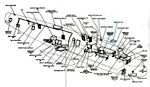 |
Emergency equipment and exits. Anything specific
to one variant is noted. Anything not noted is common to all variants.
(Extract from EO 05-25A-2) |
Credits and References:
1) Leo Pettipas <lpettip(at)mts.net> Associate Air
Force Historian. Air Force Heritage and History 1 Canadian Air Division.
Winnipeg, Manitoba.
2) Lancaster engineering manual EO 05-25A-2 dated 30
August 1957
3) F224 camera info : http://pubs.aina.ucalgary.ca/arctic/Arctic3-3-150.pdf
4) F224 and K17 image: www.ngs.noaa.gov/web/about_ngs/history/camera_timeline_web.pdf
5) Canadian Military Journal Vol 9 No. 1: Canada's Arctic
Sky Spies: The Director's Cut by Sean Maloney
Back to Lancaster Main Document
Sept 06/10

