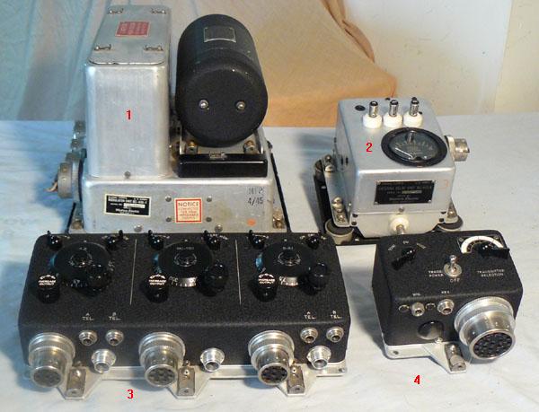
The American SCR-274N "Command" radio system consisted of three receivers and two transmitters in a configuration specific to the Lancaster MR/MP. It was used for short range aircraft to aircraft connunications.
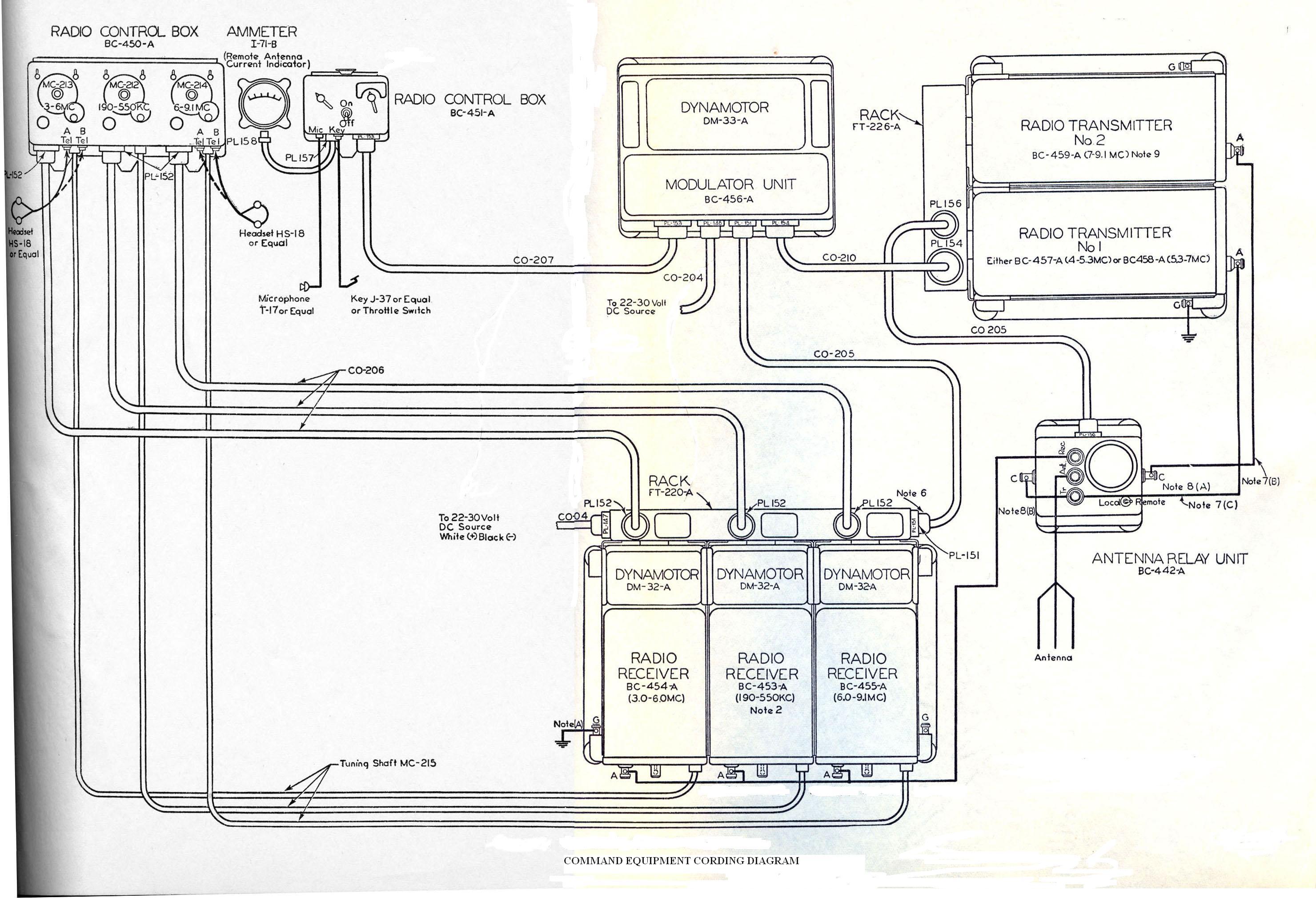
An FT-220A chassis connects three receivers and the BC-450 remote control box. Frequency coverage is 190 to 550 KHz, 3 to 6 MHz and 6 to 9 MHz. A remote control permits independent selection of frequencies on each receiver. A FT-226 rack supports two transmitters which are pretuned to their required operating frequency which can be in the bands 4 to 5.3 MHz or 5.3 to 7 MHz and 7 to 9.1 MHz . Also connected is a voice modulator unit (BC-456B), remote control box (BC-451) and an antenna changeover unit (BC-442). Selection of either CW, voice or MCW operation is facilitated by the remote control box. A fixed, wire antenna mounted on the starboard side of the Lancaster aircraft is shared between receiving and transmitting via the antenna changeover relay. Audio from all three receivers can be applied simultaneously to the station boxes via JBR No.1 and adjusted individually from the remote control box. .
In the US Army, SCR-274N series radios were available in black wrinkle paint, or natural aluminum finish. The equivalent US Navy equipment (referred to as ARC-5 series) were shipped with black wrinkle paint only. In the Lancaster, the radios were normally bare aluminum but on occassion both types could be found.
Transmitter Power Output: 24 watts
Transmitter Input Power (each) : 28 VDC @ 9 amps at full power and
2.5 amps when in standby.
Receiver Input Power (each) : 28VDC @1.6 amps
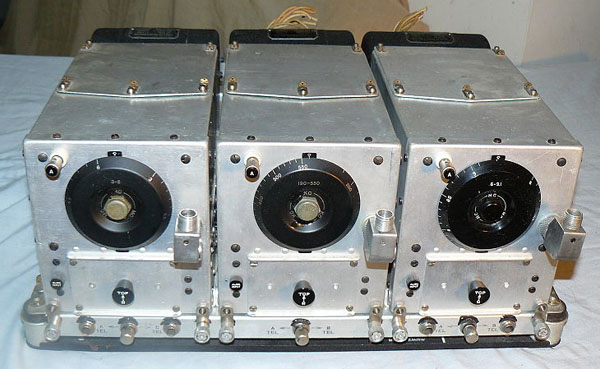 |
| Three receivers in FT-220 rack. (Photo courtesy Wikipedia) |
 |
| Typical black crinkle finish receiver. (Photo by Jerry Proc) |
 |
| FT-220 rack and FT221 mounting details for three transmitters The rack for the two transmitter configuration was similar. (Signal Corps photo) |