CANADIAN NEPTUNE P2V7 - ELECTRONICS SUITE

RCAF Neptune Electrical System

The electrical generating system consisted of two DC generators mounted the starboard engine and another DC generator plus an AC generator mounted on the port engine, an adequate system for the ASW package in the aircraft when it was delivered. However, around 1960, the Julie-Jezebel system modifications created a weak point in the electrical system in that, with all the ASW equipment in use, the DC load suddenly thrown on a single generator (if, for instance, the starboard engine were shut down) would severely overload that generator probably causing it to disconnect which would throw the load on the batteries depleting them in a matter of a few minutes. With a starboard engine failure on takeoff, the engine had to be left wind milling long enough to shed enough electrical load so that the single DC generator wouldn't be overloaded. The result could be a complete electrical failure. It was considered that this condition posed no extra risk to local flying such as pilot and flight engineer training when the ASW equipment was not in operation.

The device labelled as "air sniffer" is properly called the sensor for the Exhaust Trail Indicator (ET1).  This device was intended to detect the diesel exhaust from Russian diesel submarines. To be effective, the aircraft had to fly at a  dangerously low altitude of around 150 feet, something the pilot did not really want to do. 


neptune_ topside_features.jpg
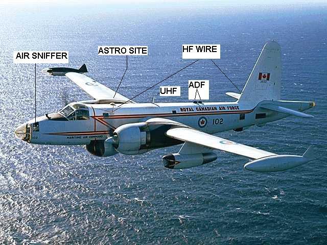
Neptune principal topside features. (Canadian Forces Photo) 
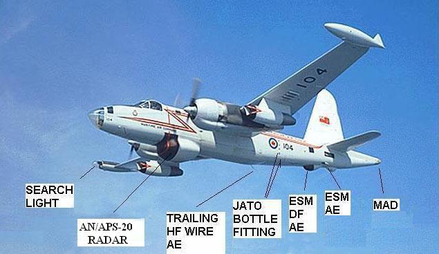
Neptune principal underside features AE= antenna. MAD = Magnetic Anomaly Detector. The 'bump' aft of the ESM DF antenna is a tail skid to protect the MAD boom.  The upper collision light is on top of the tail fin. (Canadian Forces Photo) 

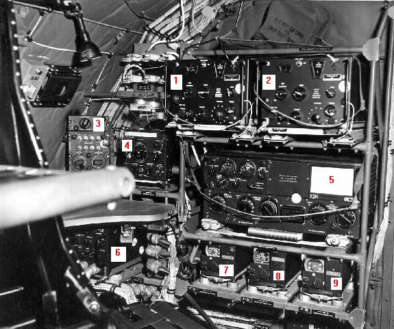
The era of the Neptune's electronics suite shown below is not known this time. Nearly all of this equipment appeared on a single page in one of the Neptune manuals.

NEPTUNE P2V7 ELECTRONICS MANIFEST
TACTICAL 
AN/APS20-E S-Band search radar, 2880 MHz +/- 30 MHz. Manufactured by Hazeltine and General Electric. 2 megawatt power output (pulse peak) for the 'E' version. Range up to 200 nm. 

Display (Photo by Jerry Proc)
APS-20 principal parts ( Courtesy Tpub.com) 
Actual components

AN/UPD-501 ESM set. High Probability Radar Early Warning directional finding receiver which was used to detect radar emissions in the X and S bands. Used by the ECM operator. It could only be used if the main radar was shut off otherwise stray RF energy would burn out the crystal diodes in the horn assembly. In the shipborne version, this problem was later solved by installing a shutter in the each of horn throats. 

AN/UPD-501 receiver (Photo by Jerry Proc) 

AN/APX-7 Recognition Set ( aka IFF Interrogator-responser). Used by the radar operator. The controls were at the radar operators station.  Maximum 2 kw power output.  Receiver frequency range: 1090 to 1110 MHz.  Transmitter frequency range: 1010 to 1030 MHz. Consists of Receiver-Transmitter RT-261/APX-7, Coder-Synchronizer KY-84/APX-7 and Radar Set Control C-1040/APX-7. The APS-20 IFF return was presented behind the target as a series of bands, the same width as the radar beamwidth.  The operator would expand the scope scale to read the returned code "value". 
AN/ APX-7 Control head photo (Photo by Jack Sullivan WA1TEJ)
RT261 APX7 Tx/Rx  (Photo courtesy Edelpro Museum)
AN/APX-25  L-band IFF transponder. Used primarily by the pilot and co-pilot. The controls were on the cockpit centre stand. Range: 800-1300 MHz, output 1 KW pulse

Notes: The updated RT-82/APX-6 was the RT-279/APX which was the RT-82 with a front panel AN connector and an internal switch that enabled the external SIF circuits. The RT-279 was connected to a KY-95A/APX-25 coder-keyer and a C-1128/APX-25 Code Selector (64 codes possible). Control Coder Group box was a C-1158/APX-25. 

Transponder RT279 (Photo by Jack Sullivan) 
Coder KY95  (Photo by Jack Sullivan) 
Control Coder Group C1158 (Photo by Jack Sullivan) 
Coder Control C1128 SIF panel (Photo by Jack Sullivan) 
Control Coder Group C1158 (Photo by Jack Sullivan) 

AN/APR-9B ECM receiver. Used for the detection of bearings for radar and radio signals by the ECM operator. 1,000 to 10,750 MHz. Made by AIL, Collins and other companies. The ESM kit was the same as that carried by the USN P2V7 aircraft, and was externally visible as a pair of teardrop-shaped fairings on the underside of the aft fuselage.

TN-130/APR-9 Tuner -  4,300 to 7,350 MHz.  (From manual C12-107-000/MB-002) 
C654A/APR9B Receiver Control Unit. (From manual C12-107-000/MB-002) 

AN/APA-69A Automatic Airborne Direction Finding set or Radar Intercept Receiver depending on source. To determine bearing of radio and radar signals.  Manufactured by RCA. Used by ECM operator. 

Unit photo. (Credit unknown)

AN/APA-74  ESM. Signal Pulse Analyzer.  Manufactured by Loral Electronics. Circa 1964. This device is designed to analyze the video output of any standard intercept receiver and is used in conjunction with radar receiving equipment. Pulse analysis information is displayed on all the traces of a five gun CRT.  Each trace has a different calibrated time base. Scales are provided to enable direct measurement of pulse repetition frequency, pulse width and rise time. In addition, the use of a watch will determine  the modulation pattern  and the scanning rate of the received signal. Shown in the photo is the analyzer/display on the left and the power supply on the right. Used by the ECM operator. 

Analyzer/display  (Photo courtesy Southwest Museum of Engineering Communications and Computation)

KD2  Oscilloscope Camera. When used, this 35 mm film camera was attached to the face of the IP37/APA-74 indicator to photograph  any signals intercepted by the ESM system. Displayed on each photograph were the five traces with associated scales, time, exposure number  and annotated information on the data plate. Power for the KD-2 was obtained from a receptacle on the on the face of the ESM junction box.

Unit photo(From manual C12-107-000/MB-002) 

AN/ARR-26 Sonobuoy/Bathythermograph Receiver; manufactured by Texas Instruments. Used by the Navigator.
AN/ASQ-8  Magnetic Anolomy Detector.  The ASQ-8 is designed to detect submarines from low flying aircraft. The presence of a submarine is indicated by deflections of an inked trace on a paper chart recording meter. Detection range is 500 yards. (See Footnote 2). Used by the Recorder Operator. 

ASQ-8 system components . (Courtesy Tpub.com) 

AN/APA-16 The AN APA-16 is a low altitude radar bombsight attachment designed for use with search radar that is intended for use in bombing surface vessels from aircraft but can also be used against any target within radar range. Used in conjunction with the APS-20. 

Altitude: 50 to 500 ft 
Aircraft to Target Velocities (closing rate): 50 to 400 knots. Pulse Repetition Rate: 2, 000 Hz. Consists of:  Control Unit, C- 160/ APA-16, Range Marker Unit SN-12/APA-16 and a Capacitor Unit, MX-139/APA-16. Total weight 36 pounds. Made by Western Electric.  It was installed at the radar operator's station and used by the radar operator. Circa 1949.

APA-16 electronic components (Courtesy Tpub.com)

AN/SSQ-2 Sonobuoy transmitter. Click on link for details.
AN/AVQ-2 Searchlight set. 70 million candlepower It could be trained in azimuth and elevation by a joystick operated by the co-pilot.

Unit photo. (part of DND photo) 

JULIE JULIE sonobuoy system. See explanation elsewhere in this document.
JEZEBEL JEZEBEL sonobuoy system.  See explanation elsewhere in this document. The Neptune was fitted with the AN/AQA-3 recorder. It could only be used with JULIE. The American AN/AQA-1 sonobuoy system was not used in Canadian aircraft, however this AN/AQA-1 training video goes a long way  in helping to explain how underwater targets were detected using sonobuoys.
COMMUNICATIONS 
AN/ARC-3 VHF radio set. Used by the pilot or co-pilot. The controls were mounted in the cockpit  centre stand. Airborne set. Separate transmitter (T67) and receiver (R77). Frequency Range: 100 to 156 MHz. 8 crystal controlled autotune channels; 8 watts output. Mode: Voice only. (Photos by David Pope) 
AN/ARC-27  UHF radio set.  Used by the pilot, co-pilot or the navigator. The controls for the pilot and co-pilot were mounted in the cockpit centre stand.  Consists of RT-178/ARC-27 UHF aircraft receiver-transmitter. Frequency Range 225-399.9 MHz; Modes: MCW/Phone; Power output: 9 watts; 18 preset frequencies on any one of 1750 frequency channels. Transmitter may be tone modulated at 1020 Hz for emergency or direction finding purposes. One guard channel in the 238- 249 MHz range can be simultaneously monitored.

AN/ARC-27 exterior view. (Photo courtesy:  www.Radiosamling.dk)
AN/ARC-27 interior view.   (Courtesy Fair Radio Sales) 

AN/ARC-38 Aircraft Transceiver. Frequency range: 2 to 25 MHz . Modes: A1, A3. Power output: 100 w.  Frequency Control: VFO control with 20 channel autotune. The AN/ARC-38A added  SSB capability. Weight 138 lbs. Used for Liason Communications. By 1965, the Neptune had two radio fittings - the ARC-38 transceiver and the ART-13 transmitter/ARR-15 receiver combination.  Most of radio ops preferred the ART-13 as it was a better set for sending Morse. The ARC-38 was easier to use but better suited for voice communications.

Unit photo. (Photo by John Mackesy VK3XAO) 

AN/ART-13  HF autotune Liason transmitter made by Collins.  Used by the radio operator only. Frequency range 1.5-18 MHz and 200 to 600 KHz if the low frequency oscillator is installed in the transmitter. Modes: CW/ MCW and AM  It has ten autotuned preset channels Power output is approximately 100 watts. The transmitter shown has the optional  LF/MF oscillator installed. 

Transmitter only. (Photo courtesy Collins Club web page)

AN/ARR-15(2)  Used by radio operator only. Remotely-tuned, 10 channel receiver. Frequency coverage: 1.5 to 18.5 MHz .

Tubes: 5 x 12SG7, 5 x 12SJ7, 2 x 6SL7, 1 x 12A6, 1 x 12H6
Junction Box: J-36A / AJA-2A and Jack Box: J-22B/ARC-5
Power Supply: 26.5 VDC 15A .Dimensions: 7 7/8 x 10 3/8 x 21 9/16
Weight: 39 pounds with dynamotor DY-34
For photo, see radio operator's position below table . 

AN/AIC-5B Interphone equipment. Used by all crew members. See item 6 in Radio Operators position photo. 
IC/VRW-7 Wire recorder. Installed at the navigator's station in order to record interphone transmissions. Circa 194?. Made by CBS-Columbia. 

Unit photo. (Courtesy www.museum.uec.ac)

LM-14  Frequency meter. The equipment provides accuracies of 0.02 per cent in the 125 - 2000 KHz range and 0.01 per cent in the 2,000 - 20,000 KHz band, at any ambient temperature in the range from -32 to plus 65 degrees C. Used for checking radio equipment.

LM-14 (Courtesy Kurrajong Radio Museum)

ARC-505/ 
Collins 618T
HF transceiver. Frequency Range: 2-29.999 MHz in 1 KHz steps. Modes: AM, CW, USB, LSB, Data. Power requirements:  28VDC or 115 VAC 400 Hz. Power Output AM/CW:  125W. SSB: 400W PEP.  Installed on aircraft used a/c used by Maritime Proving and Evaluation Unit (MP&EU) and some aircraft of 407 Squadron) 

618T photo.   (Photo by John Mackesy VK3XAO)

Trailing Wire
Antenna
There was no automatic antenna tuner so wire was trailed out to match the wavelength in use. The listed length of the wire was approximately 120 feet.  In one Neptune, the radio operator wanted to confirm that length so he ran it out to the full length.  Apparently the wire wasn't attached to the drum and is probably still in the woods near the Halifax 
beacon. Before landing there was always a visual inspection of the wire drum to make sure the wire was not deployed.  If it was left out by accident, it  snapped off pretty quickly on landing. 
 
NAVIGATION 
AN/ARN-6(2) Radio Compass set. Used by pilot and co-pilot.
AN/APN-22 Radio altimeter. Used by pilot. Manufactured by Electronic Assistance Corp. Operates on FM between 4200 to 4400 MHz, 0 to 10000 feet over land. Up to 20,000 feet over water. Transmitter Power Output: 1w nominal. Accuracy: ± 2 ft from 0 to 40 ft; + 5% of the correct terrain clearance from 40 to 20,000 ft.  A reliability circuit disabled the indicator when the signal is too weak to provide reliable operation. Main units consist of an Electronic Control Amplifier AM-291/APN-22,  Height Indicator ID-257/APN-22, Radar Receiver-Transmitter RT-160/APN-22

Photo of system components (Courtesy of Tpub.com)

AN/ARN-12
R-122A
Marker beacon receiver. Used by pilot and co-pilot. 75 MHz. Manufactured by Remler Co., Ltd

Receiver unit. (Courtesy BPB Surplus)

AN/ARA-25 UHF Homing adapter. Requires UHF radio capable of  225-400 MHz reception. Modes: A2, A3. Circa 1952.  Used by pilot. 
AN/APN-70 Loran 'A' set. Used by navigator .  Manufactured by Dayton Aviation Radio & Equip Corp.
Mark 1A  Ground Position Indicator. Gives continuous position or aircraft's ground position. Used by navigator.

ADDITIONAL NOTES ABOUT THE ELECTRONICS SUITE

RADIO
neptune_radio_ops_ver2.jpg
This is not the Radio Ops position in a Canadian Neptune, however it has all the right equipment in a single rack so it's useful for illustrative purposes.   (Photo from the collection of Dave Ross, N7EPI) 
 
ITEM MODEL DESCRIPTION
1 Collins R105/ARR15 receiver Remotely-tuned, 10 channel receiver. 1.5 to 18.5 MHz 
2 Collins R105/ARR15 receiver Remotely-tuned, 10 channel receiver. 1.5 to 18.5 MHz 
3 Light dimmer panel Below the dimmer panel is the Audio Mixing Control box for the various audio feeds from the radios. Up to 
five independent interphone loops could be used.
4 LM14 Frequency Meter Frequency range: 125 KHz to 20 MHz
5 Collins ART-13 Transmitter CW and AM. Uses auto tuning for eleven different frequencies in the range of 2 to 18 MHz . 125 watts output.
6 AN/AIC-5 Interphone
Amplifier
For all crew positions.
7,8 and 
9
  Possibly a regulator unit for the plane's alternator or generator
AN/APR-9 ESM TUNERS

AE= antenna

TUNER TUNER 
RANGE (MHz)
SEARCH 
AE
SEARCH AE
RANGE (MHz) 
DF ANTENNA DF AE RANGE
TN128/APR9 1,000 - 2,600 Lockheed
616097
1,000 - 4,450 AS5-21 (XP1)
APA69
1,000 to
10,750 MHz
TN129/APR9 2,300- 4,450
TN130/APR9 4,300- 7,350 Lockheed
616096
4,150 - 10,750
TN131/APR-9  7,050 - 10,750

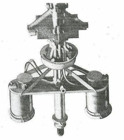
AN/UPD-501 SHF DF RECEIVER

The UPD-501 was a High Probability Radar Early Warning directional finding receiver which was used to detect radar emissions on the SHF radar bands and gave some indication of the frequency in use, bearing, and the antenna rotation period. The receiver was connected to an airborne version of a horn antenna assembly.

This device was the outcome of a project initiated by Naval Headquarters, and was a contemporary of the early MAD work.  It was a wide-band dual-band electronic countermeasures (ECM) receiver system.  This project was started in the early 1950s by the National Research Council who undertook to develop "a simple “instantaneous” direction-finding receiver-display for detection of non-co-operative radar transmissions expected to be of short duration".  It was designed to listen for radar emissions from submarines, surface vessels and even aircraft.

When the UPD-501 was fitted to the Neptunes, it did not prove viable, at least in the East Coast squadrons.  The plan was to attach the antennae “cans” to the bottoms of the wing tip tanks, but there were problems with the mounting brackets due to cracking. In some cases the receiver was removed from the aircraft once the cracks were detected. Also, the UPD-501 set was damaged if it and the radar were both turned on at the same time.  Curiously, these factors do not appear to have posed a problem for Comox-based 407 Squadron, whose Lancasters and Neptunes were equipped with the AN/UPD-501. [1]

neptune_updcans.jpg
This photo shows the position of the AN/UPD-501 "cans" on the external port and starboard fuel tanks. (Photo source unknown) 

 
neptune_upd501_ant.jpg
Airborne version of the UPD-501 antenna with radome removed. (Photo courtesy RCN)
MAGNETIC ANOLOMY DETECTOR
One disadvantage of the sonobuoy was that the submarine had to be making noise before it could be pinpointed. By shutting off the engine and gliding, the submarine could effectively slip out of the sonobuoy range and escape. To counter this tactic, the Navy introduced the Magnetic Anomaly Detector. As the name implies, it does not rely  upon the sounds made by the sub, but by changes caused in the magnetic field as it moves. Because of its limited range, MAD was unsuitable for area search. However, it was useful in pinpointing a target that had been detected by other means.

A major drawback of the available MAD equipment lay with the fact that the aircraft had to be flown at very low altitudes (50 feet was optimum) to ensure that maximum signal strength was obtained. This meant that there was very little warning when a submarine was detected.

EXHAUST GAS DETECTOR (AUTOLYCUS) also called ASH

The Exhaust Gas Detector was a device used to measure the quantity of particulate matter in the air. A venturi type device was mounted up near the nose and a hose connected it to the 'black box' where the incoming air was humidified and then passed through a chamber.  There was a light on one side of the chamber and photoelectric sensor on the other.  The relative quantity of particulate matter was displayed on the AJH(?) 501 chart recorder using a heated stylus. As the thermal paper was drawn through the recorder below the stylus, it would leave a track on the paper. The same recorder also used for Julie (EER).

The aircraft flew very low over water hemstitching upwind, looking for a submarine diesel exhaust trail.  Once detected the a/c would crisscross the exhaust plume while working its way up wind, up the trail.  The width of the trail would normally narrow as the aircraft got closer to the origin.  To be effective, the aircraft  had to be very low, something the pilots hated. Once a target was found, it would be illuminated with the searchlight and then depth-charged. It was nice in theory but the pilots weren't very thrilled with it since that was a technique and technology  left over from WWII.

JULIE and JEZEBEL SONOBUOY SYSTEMS

JEZEBEL

JEZEBEL is a passive sonobuoy system which was used for area searches and localization only so far as the 16 sonobuoy channels of the SSQ-2B system would provide. JEZEBEL processes sound information by analyzing the sounds in the sea  into their frequency components and displaying the information on a continuously moving graph in a frequency vs. time format. Each type of surface ship and submarine has a unique frequency "fingerprint" that allowed the JEZEBEL operator to identify the type and the nationality of the target. The technical term for JEZEBEL was "LOw Frequency Analysis and Recording" or LOFAR. Once a submarine was detected with JEZEBEL, then JULIE was used to help refine the position. . Incidentally, the 15-buoy JULIE circle was nicknamed "the Cadillac pattern" as one could allegedly buy a car for the price of the buoys.

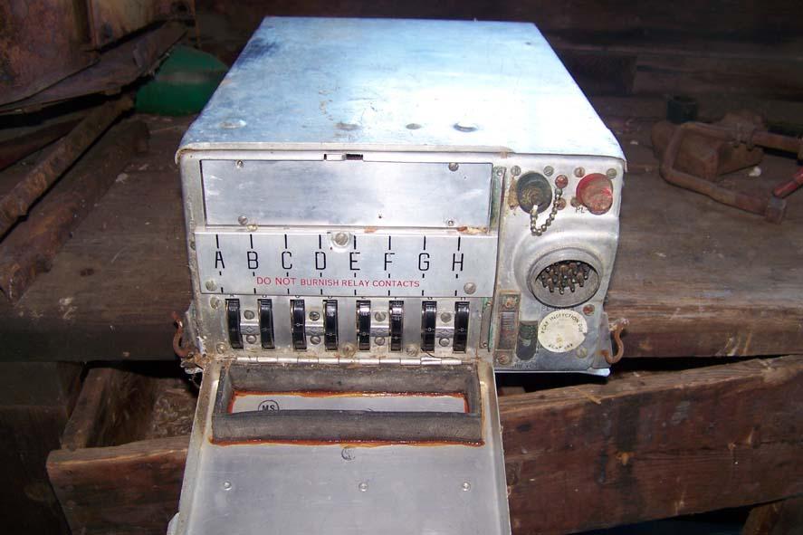
The AQA-3 and AQA-4 were the recorders used for JEZEBEL. The AQA-3 used four 3", side-by-side, printouts of continuous input - frequency on the X axis and time on the Y axis.  The West Coast Neptunes may have been fitted with the AQA-4 later in their service lives. The only difference between the -3 and  -4 was an additional knob on the AQA-4 for a 'correlate' function since it could perform a correlation/detection (CODAR) analysis.
 

JULIE

JULIE was an active sonobuoy system which used the technique called Explosive Echo Ranging (EER). After the sonobuoys were deployed,  the aircraft would then drop a small explosive charge into the water known as a Practice Depth Charge (PDC). When it exploded, the percussion wave would bounce off the submarine and the operator would listen for the resultant echo.  The system used a paper tape printing  recorder and 'Julie rulers' which were calibrated for distance  based on ocean temperature.

The disadvantage of JULIE is that the PDC detonations announce to the submarine that it is about to be attacked. Naturally, the submarine executes the maximum evasive manoeuvres (dispense decoys, change depth, turn and take advantage of oceanographic features that would minimize JULIE detection ranges). A well worked up crew (JULIE demanded the highest degree of crew coordination) could attack an evasive submarine before it could exit the JULIE sonobuoy containment pattern. If the submarine increased speed, it generated more noise and increased JEZEBEL detection ranges.

By the way, two buoys (SSQ-2B Mod 9) bombed with PDCs would give an ambiguous fix (the arcs would intersect on both sides of the baseline), so a third buoy would be  needed to 'resolve the ambiguity' or, alternatively, carry out a MAD sweep across both fixes to see which one was the correct one.

A regular passive sonobuoy could be used for JULIE but it was more expensive to do so. Initially, only one type of sonobuoy was used for JULIE and JEZEBEL  but later there were 'dedicated' buoys for each system. The dedicated JULIE sonobuoy was less sophisticated and cheaper because all that was needed was a sensor to detect the PDC "white noise" detonation and the returning echo. Whereas the JEZEBEL sonobuoys were more sophisticated because they were frequency sensitive. There were other design techniques inherent in a JEZEBEL buoy which were used to dampen the ambient sea noise (rain, wave motion, sea life, flow noise around the hydrophone, etc). Later, in the post-Neptune era, a more sophisticated "DIrectional Frequency Analysis and Recording" or DIFAR sonobuoy also provided direction to the frequency source.  JULIE was the only EER system. It was supplanted by active sonobuoys that generated their own "ping" similar to a ship's sonar, negating the requirement to drop PDCs.

After the initial detection a submarine was a localized by refining the datum down to attack criteria. In broad terms, one could look at the detection system as getting more accurate when going from SOSUS to JEZEBEL to JULIE to MAD. Getting from JEZEBEL to JULIE often required a visual or radar contact though, especially on a snorkelling submarine.

Generally, an acoustic operator was trained to operate both JULIE and JEZEBEL systems. But most Neptune  crews operated JEZEBEL and JULIE simultaneously requiring two operators. In the Neptune era, the usual tactical sequence was to detect the submarine initially on JEZEBEL and determine a "rough" fix on its position; then JULIE was used to refine the submarine's position to sufficient accuracy to conduct a multiple torpedo attack. MAD was used during the attack run to confirm the accuracy of the JULIE datum on which the attack was made. Meanwhile the JEZEBEL operator continued to track the submarine, providing indications that the submarine had turned or changed depth.

FOOTNOTES:

[1] As noted in the article "Early Cold War Anti-Submarine Warfare Development in Canada" by Leo Pettipas.
The exact reason as to why the UPD-501 was more successful in the West is not known at this time.

[2]  From the Naval Institute Guide to World Naval Weapons Systems, 1991/92  by Norman Friedman.


Credits and References:

1) Ernest Cable - Associate Air Force Historian and  Shearwater Aviation Museum Historian <erncar(at)ns.sympatico.ca>
2) Bert Campbell <navigator1(at)eastlink.ca>
3) Leo Pettipas <lpettip(at)mts.net> Associate Air Force Historian. Air Force Heritage and History 1 Canadian Air Division.Winnipeg, Manitoba.
4) Jim Loring  <j.s.loring(at)shaw.ca>
5) David C. Fletcher <dcf(at)mars.ark.com>
6) David Ross  ross@hypertools.com
7) Ian Snow <va3qt-4(at)sympatico.ca>
8) APA-16 specs.  http://www.tpub.com/content/radar/TM-11-487C-1/TM-11-487C-10679.htm
9) IC/VRW-7 photo:   http://www.museum.uec.ac.jp/database/sf/sf0/s32.html
10) http://hereford.ampr.org/millist/pic/arn-12.jpg
11) ARN-12  http://www.bpbsurplus.com/lc/cart.php?target=search&substring=arn-12
12) LM14 photo   Kurrajong Radio Museum http://www.vk2bv.org/museum/lm.htm
13) APX-25 control panels.  Old Cockpit Panels  http://members.chello.nl/m.waterloo/t33-panel.html
14) John Mackesy VK3XAO <mack(at)melbpc.org.au>
15) Gorka L Martinez Mezo <glmm(at)gmx.net>
16) Fred Weir <fweir(at)live.com>
17) Jack Sullivan <wa1tej(at)yahoo.com>
18   RT261_APX7 photo courtesy http://www.ase-museoedelpro.org/Museo_Edelpro/Catalogo/
       Overview/new_comm_mil/Mil_RT-261A_APX-7/RT-261A_APX-7.pdf  emilio.ciard(at)tin.it
19) Greenwood Aviation Museum   http://www.gmam.ca/neptune.htm

Back to Neptune Main Document
Nov 26/18