| SENSORS and TACTICAL |
| |
|
| AN/APS-504(V)? |
This was the radar in the maritime reconnaissance version
only. It was used by the AESOP and available at the 4th seat only. Originally
designed for antisubmarine warfare applications, it represented the next
generation in digital X-band airborne search radar in the mid 1980's era.
It also provides the operator with the capability to detect small targets
up to 200 - 250 nm and to conduct search and rescue patrols, maritime
surveillance, ice patrols, anti-submarine watch, weather detection, and
beacon interrogation. One of the variants was made by Northrop Grumman
Canada, which is now part of L-3 WESCAM, Burlington, Ontario, Canada. Other
variants were made by Litton Canada. The variant carried on the Tracker
is not known at this time. (Need photos)
Select here for Technical specifications |
| AN/ARN-504(V)2 |
TACAN - D/F and DME (Distance Measuring Equipment) . The
D/F antenna was atop the cockpit while the DME antenna was on the tip of
the tail below the rudder. (Need photo of equipment) |
| AN/APN-503 |
Doppler radar. Provides ground speed and track. Operates
between 0 to 50,000 feet. Used by Pilot and co-pilot. (Need photo) |
| AN/R1047A/A |
The On-Top Position Indicator (OTPI) is used too
provide bearing and on-top position indication of deployed sonobuoys. When
used in conjunction with a suitable ADF system, it allows the operator
to locate and verify the position of sonobuoys. Max range 26 nm. Used by
pilot and co-pilot. (Need photo) |
| AN/APX-77 |
Ultra-lightweight IFF transponder manufactured by Hazeltine.
175 nm maximum range. Controls on pilot's overhead console. The APX-77
SIF antenna was located on the vertical fin.
APX-77 Tx/Rx image courtesy <ham.brugtgrej.dk>
APX-77 combination antenna |
| |
|
| COMMUNICATIONS |
| |
|
| AN/ARC-505 |
This is the Collins 618T-3 HF transceiver. Frequency Range: 2-29.999
MHz in 1 KHz steps. Modes: AM, CW, USB, LSB, Data. Power requirements:
28VDC or 115 VAC 400 Hz. Power Output AM/CW: 125W. SSB: 400W PEP.
Used by AESOP. Reception and transmission available at all positions.
618T/ARC-505 (Photo by
John Mackesy VK3XAO) |
| AN/ARC-511 |
VHF/AM transceiver. Used by pilot and co-pilot. Controls
on cockpit console. Reception and transmission also available in 3rd and
4th seats. (Need photo) |
| AN/ARC-513 |
VHF/FM transceiver. Used by pilot and co-pilot. Controls
on cockpit console. Reception and transmission available in 3rd and
4th seats. VHF-FM was used to communicate with ships on commercial marine
frequencies (Need photo) |
| AN/ARC-27A |
UHF Transmitter Receiver. RT-178/ARC-27 UHF aircraft
receiver-transmitter. Frequency Range 225-399.9 MHz; Modes: MCW/Phone;
Power output: 9 watts; 18 preset frequencies on any one of 1750 frequency
channels. Transmitter may be tone modulated at 1020 Hz for emergency or
direction finding purposes. One guard channel in the 238- 249 MHz range
can be simultaneously monitored. Used by pilot and co-pilot. (Reception
and transmission available in 3rd and 4th seats in CS2F-3).
ARC-27 unit- exterior (Photo courtesy:
www.Radiosamling.dk)
ARC-27 unit - interior (Courtesy
Fair Radio Sales)
ARC-27 combination antenna |
| AN/AIC-8 |
Interphone. Can support 2 to 15 stations.
Control panel . (Partial photo by
Jerry Proc) |
| |
|
| NAVIGATION |
| AN/ARN-44 |
Modifed version of AN/ARN-6 radio compass. Band 1 receives
2 to 3.5 MHz instead of 100 to 200 KHz. |
|
|
| AN/ARA-25 |
UHF Homing adapter. Requires UHF radio capable of
225-400 MHz reception. Modes: A2, A3. Circa 1952. Provides homing facilities
to selected transmitter stations (UHF, OTPI, VHF/FM and VHF/AM) . Used
by pilot and co-pilot. Visual display available at 4th seat. Reception
available at 3rd and 4th seat. ARA-25 was the only receiver capable of
receiving sonobuoy signals. The Maritime reconnaissance version only had
1 sonobuoy in each nacelle. |
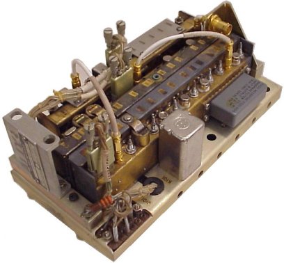
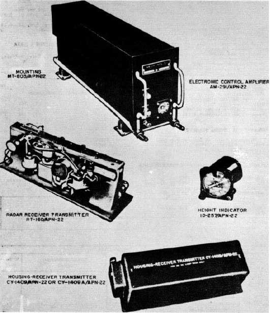
| AN/APN-22 |
Radio Altimeter. Manufactured by Electronic Assistance Corp.
Operates on FM between 4200 to 4400 MHz, 0 to 10,000 feet over land. Up
to 20,000 feet over water. Transmitter Power Output: 1w nominal. Accuracy:
± 2 ft from 0 to 40 ft; + 5% of the correct terrain clearance from
40 to 20,000 ft. A reliability circuit disabled the indicator when
the signal is too weak to provide reliable operation. Main units consist
of an Electronic Control Amplifier AM-291/APN-22, Height Indicator
ID-257/APN-22, Radar Receiver-Transmitter RT-160/APN-22
Photo of system components. (Courtesy
of Tpub.com) |
| AN/ARN-503 |
VOR/ILS and Marker Beacon receiver. VOR provides navigational information.
ILS aids landing. The Marker Beacon identifies passage over airway, outer
or inner markers. Used by pilot and copilot. Indicators available at 3rd
and 4th positions. (Need photo) |
| AN/ARN-508 |
ILS Glide Slope Receiver. (Need photo) |
| AN/ARN-509 |
Omega Long Range radionavigation receiver. The Omega system, which
operated in the 10 to 14 KHz band, was shut down in 1997.(Need better photos)
Photo of front panel.
Closeup of C5306 front
panel. (From manual C12-107-000/MB-002) |
| VIR-31 |
Collins navigation radio. The military version of this radio is called
the AN/ARN-140 but the Tracker's maintenance manual uses the commercial
VIR-31 designator. It indicates use with the AT-640 antenna.
Photo of unit (Courtesy Southeast
Aerospace) |
|
|
| SEARCH and RESCUE RELATED |
| |
|
| AN/PRQ-501 |
Personal Locator Beacon (PLB). Two way radio for voice and homing operating
on 243 MHz . A total of 5 were carried.
Photo of AN/PRQ-501 (Courtesy: Simple
Machines Forum) |
| AN/URT-505 |
Portable Emergency Locator Transmitter. (ELT). Provides homing transmission
on both 121.5 and 243 MHz. Can be used by any crew member. Located
on Third seat bulkhead. It must be physically turned on by the crew
after the antenna is manually attached. (Need photo) |
AN/URT-508
(DAPI 8) |
Downed Aircraft Position
Indicator.
A fixed set which provides homing transmission (only) on 243 MHz. Can be
flashed up manually by the pilot or co-pilot or automatically by ground
impact or submersion in water. The manual deploy switch was in the overhead
pilot's console. Ground impact switches are located in the nose cap and
wing tips. A submersion switch was located in the radar dome. (Need photo) |
|
OTHER
|
| Model unknown |
"Codfish" Computer. For local on-board storage of communications logs,
photos, and holding current fisheries license lists. (Need photo and tech
info) |