|
The equipment described in this section could be found on different ships in the Royal Canadian Navy during the 1940's. AR77 Receiver A commercially built, 540 to 31000 kc receiver, produced by RCA Victor and sold for $139 in the early 1940's.
|
During World War II, installation of communications equipment in Canadian Ships generally consisted of a pattern which is summarized in the chart below. Shown, is the quantity and type of equipment fitted on different classes of ships. This is by no means a comprehensive listing as ships always had minor variances in their fittings. An asterisk (*) means that only the Group Leader would have this gear installed. All this equipment is explained later in this chapter.
| TYPE | ALGERINES | BANGORS | CORVETTES | DESTROYERS | FAIRMILES | FRIGATES |
|---|---|---|---|---|---|---|
| CM11 | 2 | 1 | 1 | 2 | 1 | 2 |
| FR12 | 1 | 1 | 1 | 2 | 1 | 1 |
| HF/DF | 0 | 0 | 0 | 1 | 0 | 1 * |
| HT11 | 1 * | 0 | 0 | 1 | 0 | 1 * |
| MF/DF | 1 | 1 | 1 | 1 | 0 | 1 |
| PV500 HM | 1 | 1 | 1 | 1 | 0 | 1 |
| PV500 LM | 0 | 1 | 1 (on some) | 1 | 0 | 0 |
| TBS | 1 | 0 | 1 | 1 | 0 | 1 |
| Notes:
During the early program, Fairmiles ML050 to HMC ML111 inclusive, left their builders yard with the FR12/MSL5 station combo. As CM11's became available they replaced the FR12. The Canadian Marconi Company was incorporated in 1903 as the Marconi Wireless Telegraph Company of Canada. This enterprise grew out of Guglielmo Marconi's successful sending of a message across the Atlantic in 1901. The new company was designed to take advantage of the Marconi Company's patent monopoly rights it had acquired from the Canadian government. A transatlantic wireless station was erected on Cape Breton Island. Soon afterwards, the company began to build coast stations to communicate with ships at sea. During World War I, Marconi began to manufacture electrical and radio equipment in its Montreal factory. After the war, its interest extended to commercial broadcasting with the establishment of CFCF Montreal, one of the first public radio stations in the world. The name was changed in 1925 to Canadian Marconi Company (Limited). By the 1930s CMC was firmly established in three main areas: coast and beam stations, radio manufacturing and broadcasting. During World War II, the company underwent enormous expansion in order to build military communication equipment. This military work continued in the post war period. Canadian Marconi was a leading provider of equipment to the RCN. |
|
The equipment described in this section could be found on different ships in the Royal Canadian Navy during the 1940's. AR77 Receiver A commercially built, 540 to 31000 kc receiver, produced by RCA Victor and sold for $139 in the early 1940's.
|
B28 RECEIVER
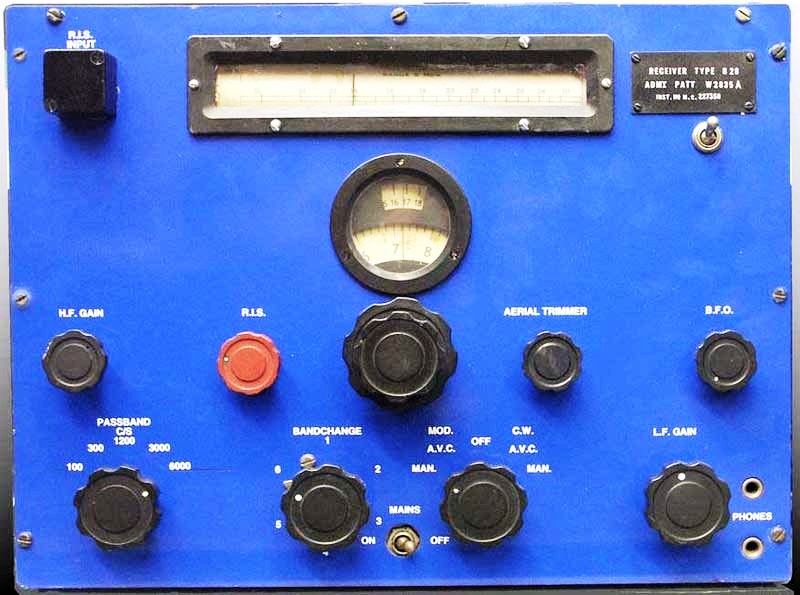 |
| Power input - 200/250 VAC, 50 Hz @ 85 watts or batteries.
Weight - 82 pounds. Dimensions - 16 x 16.5 x 12.5 inches Band coverage was 60 to 420 kc and 500 kc to 30 Mc. (Photo credit unknown) |
George Dance served two years national service as a telegraphist in the Royal Navy and a further twenty years in the Royal Naval Reserve. He explains the modifications made to the B28 receiver that he used while in the RNR. "The receiver was a B28 but had been modified with a 10 watt CW transmitter fitted inside the lid. The tuning was via plug-in crystals and the transmitter and modification was designed by a Lt. Compley-May for use by reservists from their homes. The HQ for my area, Severn Division RNR based at HMS Flying Fox in Bristol, would run an exercise every Sunday morning which would be monitored by Whitehall W/T and whoa betide anyone caught using incorrect procedure.Some of the reservists were issued with a standard B28 and a 5G CW transmitter which I believe was originally designed for use in aircraft. These sets were also crystal tuned. I had a 5G which was modified by a ham for manual tuning.
EQUIVALENT SERVICE TYPE NUMBERS FOR MARCONI CR100 SERIES OF RECEIVERS
Marconi Service Type Patt. No Details
Type No. No.
=======================================================================
CR100 --- --- Prototype. Low phone level. "B" gauge phone jacks.
3 ohm loud speaker.CR100/1 B28 W2835 Admiralty. High phone level. "A" gauge phone jacks. (A.P. 676).
1,000 ohms loudspeaker.CR100/2 R1297 --- Army, RAF and other services. As CR100 but with coaxial plug and
(RAF) socket fittings for aerial input and with side tone facility.CR100/3 --- --- Superseded by CR100/5
CR100/4 B28 W2835A As W2835 but fitted with scale clamping device and body guard.
CR100/5 B28 W2835B As Patt. W2835 but with coaxial plug and socket fittings for aerial input
and improved rear terminal board.CR100/6 B35 W8126 Admiralty. For use with other apparatus to comprise a Tuner Amplifier B35. Special input circuits and modifications for direction finding.
CR100/7 B28 W2835D As Patt. W2835A but with noise limiter Admiralty Patt. 56703 and
additional IF output jack.CR100/8 B28 W2835E As Patt. W2835B but with noise limiter Admiralty Patt. 56703.
CR100/8 --- --- Ministry of Supply. As CR100/8 except 3 ohm loudspeaker and B" gauge
phone jacks.Source:: arconi Manual T1868. Details of three mods can be found here Each mod indicates the CR100 variant to which it applies.
An article on the CR100 series can be found here.
| B29 Receiver
Originally developed from the Marconi CR200 receiver in 1941, this unit was a five tube TRF (tuned radio frequency) design and had a frequency range of 15 to 550 kc. The B29 incorporated two VR100 RF amplifiers, a VR99 detector/oscillator, two AF stages (6J5 and NR69) and a 5U4G rectifier tube. A narrow, 1 kc bandwidth filter was included in the audio stages for CW reception. It could operate on 120/220 VAC 50 Hz or 6VDC power sources. Power input - 100/110 or 200/220 VAC, 50 Hz @ 33 watts.
|
| CRYSTALS
A lot of electronics equipment produced during WWII used 3 prong crystals. Select this link for details on the three configurations. CSR5 During WWII, most if not nearly all Marconi CSR5's saw service in shore installations. See description in HAIDA Radio 1 section. CM11 Transmitter See description in HAIDA Radio 1 section. |
| DAS Loran 'A' Receiver
The DAU was the standard RCN HF/DF set at the end of the war and the immediate post war era . It replaced the Plessey FH4. This receiver covered 1.5 to 30 Mc in four bands but the d/f finding range was only 1-21 Mc. The power supply/scanner was mounted above the receiver while the auto bearing indicator and goniometer were mounted in a skeleton frame reminiscent of modern radar Plan Position Indicator (PPI). Both the bearing and frequency were presented on a 5 inch cathode ray tube. The DAU is a DAQ modified for use with a panadapter (+/- 75 KHz). Identification: DAU receiver number is CFT-46243 while the power supply
is CFT-20241.
ET-8022A Transmitter |
| DF Outfit Nomenclature
DF outfits (aerial, receiver and goniometer) produced for the
British Admiralty used the nomenclature
FIRST LETTER A = Adcock aerial system
SECOND LETTER A = Alternative HF/DF or MF/DF
FH-1 HF/DF Outfit This set was never used by the RCN. It is just listed here for reference. FH-2 HF/DF Outfit There is no evidence to show it was ever used by the RCN so its just listed here for reference. FH-3 HF/DF Outfit Used by the RCN, it relied on operators manually scanning suspected U-boat frequencies. Detection was provided by an audio signal heard in a headphone.Distance was impossible to determine accurately, but operators soon learned to distinguish HF ground waves from sky waves. Since ground waves could only be detected 12 to 14 miles from the transmitter, FH-3 operators knew when an intercepted signal represented a dangerously close U-boat. The FH-3 incorporated the B21B receiver which had a frequency coverage from 1 to 20 Mc. It was connected to a fixed aerial system consisting of two crossed, screened loops (Bellini-Tosi system) for direction finding and a vertical aerial for sense detection. For testing the performance of the apparatus, Frame Coil S25B was used. This is an arrangement in which a signal was injected into the unit and would simulate a bearing at GREEN 45 degrees While in service, and on a weekly basis, the F/A and P/S loop coils were tested to ensure that their respective resistance did not exceed 0.5 ohms. On a bi-weekly basis, the field coils were tested to ensure that there was not more than 0.1 ohms resistance. Between either loop and ground, the resistance could not be less than 3 megaohms. Search coils could not exceed 0.3 ohms. The FH3 was powered by a 230 volt AC source, which when rectified, produced a B+ of 160 volts to run the receiver. Filament power was 6.3 volts. Photos of the FH3 receiver and antenna. FH-4 HF/DF Outfit This was a 1 to 24 Mc HF/DF receiver which had a cathode ray scope for direct visual bearing indication and was superior to its predecessor due to the ability of being able to distinguish between the sky wave and the ground wave. Its scope was as big as a pie plate, and was surrounded by a compass rose. Accuracy was limited from 2 to 10 degrees and the unit was powered by a 230 VAC 50 Hz mains source. The FH4 was connected to a Bellini-Tosi aerial array consisting of fore/aft (F/A), port/starboard (P/S) loops and a sense aerial. The initial sets were designed with five RF and IF coils that had to be changed for different frequency ranges. In 1945, the set was improved by the addition of a band changing switch. As one WWII Sparker summed it up: " Changing frequency bands was a bitch with the early model particularly since the set had to be recalibrated every time you did it. Your chances of getting a bearing on a U-boat "B-bar" message of as little as seven letters were abysmal." FH-4 photos
FM12 MF/DF Receiver
Select this link to view a listing of D/F sets fitted in some ships of the RCN. The list was complied by researcher John Wise and is a portion of a much larger list which also includes the RN. |
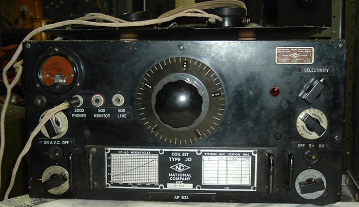
| FR12 Transmitter/Receiver
During the war years, the FR12 was a mainstay on many vessels and was used on CW for inter-communication between escort ships on convoy runs. Voice was available but rarely used. Its popularity dropped when the TBS transmitter/receiver was introduced into service. For further details on the FR12, please refer to the description in the HAIDA Radio 1 section. G56 Wavemeter Operating range was 15 kc to 24 Mc. It required 100 VDC for the high tension circuit and 4 VDC for the ilaments. Typically, they were fitted one per destroyer or one for a group of corvettes. HF/DF Equipment HF/DF equipment was mainly used to get bearings on U-boats and was usually located in the second W/T office if the ship was so equipped. HRO Receiver A 100 to 30000 kc general coverage receiver manufactured by the National Company in Malden Mass. One day, at the National plant, certain work orders in their pre-production shop were marked HOR for 'Hell of a Rush' order. Management decided that should be the name of their new receiver but in those days, HOR was politically incorrect, so the letters were switched to HRO. The HRO model variant determined the frequency range. This receiver did not have a band changing switch. Instead, band changing was accomplished by exchanging a single unit coil set which slid into the front of the receiver. Since the tuning dial was not calibrated in frequency, a tuning graph was attached to the front of each coil set. The list price of the HRO receiver was $US 350 in 1939. Another receiver in the HRO family was the HRO jr (junior). It was nearly similar to its big brother, but lacked a crystal filter, the phasing control and the S-meter. The Canadian Army/Royal Canadian Corps of Signals also used the HRO The RCAF also used the HRO. Some of their orders were in large enough quantities that National painted many of them RCAF blue. The US Navy custom ordered three HRO models which they designated RAS, RAW and RBJ. All were mounted in a standard 19 inch rack that included the receiver, a power supply, coil storage compartment and speaker panel. The RBJ and RAW are similar, roughly equivalent to the HRO Junior model. The RAS was unique in that the IF was 175 KHz; this allowed full coverage between 200 KHz and 30 MHz. All other HROs had a 456 KHz IF and omitted coverage between 400 - 480KHz but could tune as low as 175 KHz with the appropriate coil set. All of these military models had a front panel locking mechanism for the coils that is not found on commercial sets.
|
| HT11 Radiotelephone
In a frigate, the HF/DF office was under the port bridge Oerlikon and just aft of the forward gun which, if trained to port and fired, would cause all the spares to be blown out of their racks - but the sets were never affected. Probably nobody remembers this now, but the messages passed on the HT-11 and the TCS were coded in the "ZR" code to be found in the Fleet Signal Book. For example, "ZR5" meant "I have obtained the following bearing on a U-boat transmitting a B-bar message." I never got to use it". For more details on the HT-11 , select this link Loud Hail All ships were equipped with Loud Hails. The most popular types were the models TE-129 and the TE-311B. The latter's output could be switched from a hailing position to a radio entertainment position. HAIDA was fitted with the RCA Model 431 Loud Hail. MDF5 D/F Receiver
MF/DF Equipment This equipment was primarily used for taking bearings of shore, ship, or aircraft stations. BLOCK DIAGRAM |
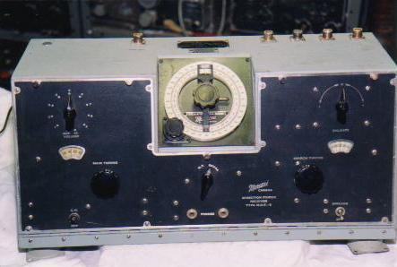
| MSL5 Receiver
If the MSL5, or its power source failed, the operator would move the antenna from the binding post marked VAL (valve) to the binding post called CRYS (crystal). Crystal headphones would have to be plugged into a separate front panel jack. An easily accessible, internally mounted, cat whisker crystal would then be manipulated until the most sensitive spot was found, exactly the way it was done with early crystal radio sets. In later MSL5 models, the cat whisker crystal was replaced with a crystal diode such as the 1N34. In crystal radio mode, stations were tuned by operating the antenna tune control in conjunction with the band switch mounted directly above it. This receiver was mainly used for the reception of shore based broadcast
messages. The example on display aboard HAIDA was painted in a dark green,
crackle finish.
|
| PV500 HM Transmitter
|
| PV500 LM Transmitter
|
| S27 Receiver
|
| SCR 522 VHF Transmitter/Receiver
After the war, the SCR 522 became available in large quantities in the surplus marketplace thus providing many amateur radio operators with an inexpensive means of getting started in 2 meter VHF. Many of these sets were supplied by the Colonial Radio Corporation to the Allied forces in 1943. The following standard RCN
crystal frequencies were available for the SCR-522 transmitter:
Select this link to see the SCR 522 internally. (Photo by Jerry Proc) |
| SMR3 Receiver
|
| Sound Reproducing Equipment
It was the job of the radio operator to man the ship's SRE and play records for the entertainment of the crew. All mess decks, including the wardroom and Captain's quarter were equipped with speakers. Besides playing the popular music of the day, the operator would usually slip in records that reflected his personal music style. Profits from ship's canteens were used to purchase new records thus increasing the variety of music in the library. In contrast, corvettes in the Royal Canadian Navy were not even fitted with loudspeakers. In order to communicate important orders, a Boson's Mate with a boson's call was used or a system of ringing bells. To overcome the motions of pitch and roll, record turntables were mounted in a rather heavy gimbals mount which kept them level. Most of the faults that occurred in the SRE were in the speaker connections or speaker cones and were induced by the firing of the ship's guns and vibrations from the ship itself. HAIDA was equipped with the AP 4660 sound reproducing system. When reception was possible, the Canadian Broadcasting Corporation was very popular among crews. Sailors usually preferred to listen to any American stations rather than the BBC.
|
 |
| The AP4660 was the model number assigned to this SRE receiver only - its not the designator for the whole SRE system,. The model number of the PA amplifier is not known at this time. The receiver alone weighs 96 pound. This exanple was last reconditioned by Vosper (UK) in 1951. When reconditioned , its serial number changed. Click on image to enlarge. (Photo credit unknown) |
| SRE 457
The model SRE 457 receiver was built by RCA Victor, Montreal in 1944. It has a 5 watt audio output. For operation on 220VDC ship's mains, it needed a motor-generator set p/n 105458-2. Depicted above is serial number 346. The equipment manifest, dated 1955, for Bluethroat AGOR114 shows the SRE457 receiver as part of the electronics fit. This radio, may in fact, be the military version of the RCA M47A receiver (Photo by André Kirouac on behalf of Musée Québécois de la radio) |
| TBL Transmitter
|
| TBS Transmitter/Receiver
From an documentation viewpoint, RCA published an instruction manual for the TBS series that was second to none. Some of the schematics are printed with multiple colours and the manual is filled with cartoon-style illustrations. There was likely a reason for this - the TBS was being supplied to a huge bases of users whose technical skills were unknown. It was great foresight on RCA's part to produce a manual that could be understood by people with little or no experience with installing or operating radios. On September 17/43, HAIDA was assigned to the Royal Navy's home fleet base at Scapa Flow for work up exercises. Here, the Royal Navy conducted a 24 hour radio exercise in manoeuvring the fleet by W/T (morse key) and HAIDA's operators were required to participate until the procedures were perfected. When the TBS and 86M units entered service, the need for fleet manoeuvring by morse key was eliminated as all further operations were conducted by voice. As TV became popular in the late 1940's and early 1950's, emissions from TBS type radios interfered with television broadcast reception. In an effort to reduce complaints from the civilian population, the RCN did not permit operation of these sets unless the ship was more than 100 nm from land. The typical communications range for these sets was 10 miles. (TBS photo by Jerry Proc) The following standard RCN
crystal frequencies (for both the receiver and transmitter)were
available when the TBS was im service:
|
This was a battery operated, portable, transmitter/receiver operating in four bands within the 28 to 80 Mc range. The transmitter used a pair of push-pull 958 acorn tunes to modulate an oscillator, an arrangement which gave 0.5 watts input. The receiver was of a regenerative design and used the 958 and 959 acorn tubes. Frequency control was accomplished with ?separate variable capacitors and band switches for both the receiver and transmitter. The audio section used a types 30 and 1E7G tubes and a separate type 30 was used for the crystal calibrator. Frequency indication was available from separate receiver and transmitter logging scales, however, most models were accompanied with calibration books which converted the log scale numbers to channel numbers, which in turn corresponded to frequencies. The transmitter and receiver filament voltages were metered and separately adjustable to compensate for discharging batteries. In the most common arrangement, a dry battery was strapped to the bottom of the unit and connected to the radio through a five pin plug. In later designs, the dry battery was replaced with a 4 volt lead acid battery and a vibrator power supply or alternately a 115 VAC/VDC power supply. The battery and vibrator arrangement brought the weight up to 50 pounds. Spare tubes were held in a hinged top cover. TBY's used a six foot sectional whip antenna which had a spring in the bottom section. Later versions incorporated a spring loaded antenna mount. When shipped, the TBY came in a wooden transit case which contained the radio, a canvas cover/rucksack, three dry batteries, the antenna, headset, key and manual. These units were manufactured by Westinghouse in Baltimore Maryland and the Colonial Radio Corporation of Buffalo N.Y. Each were made in model numbers ranging from TBY-1 to TBY-8. These incorporated minor differences such as the presence or absence of panel lights, calibration charts, dial locks and antenna fittings. One note of caution for anyone who may have a unit in their possession - all of the dials on this radio are painted with radium based paint, a substance which has since been banned from production. The TBY was not used by the RCN during WWII but not fitted aboard HAIDA. |
TE-236B LF/MF Receiver
 |
The TE-236B was a version of the American RAK regenerative receiver and built by RCA in Montreal. It was supplied to the Royal Canadian Navy during World War II. Frequency range is is 15 to 600 KHz This receiver was a lower cost verxsion of the RAK in that it does not have monitoring meters and lacks the "ADD DECIBELS" and "AUDIO TUNING" controls. RCA also made RAK's at the Montreal plant. In the Korea war era and into the 1960's, the TE236 was used to guard the international distress frequency of 500 KHz. For more info on the TE-236B, select this link. |
TE 311B Haiker
| TE 311B Hailer. Click on image to enlarge. Looking for a manual for this device. Contact: jerry.proc@sympatico.ca (Photo by Nygel Asselin). |
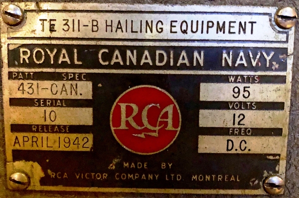 |
| TE 311B nameplate. (Photo by Nygel Asselin). |
| TV5 Transmitter/Receiver
Freq Range:
Average power input: 15 watts
Tube Lineup: Osc - KT66; Modulator - two KT66's. RF Amplifier - KT8 and KT66. Internal power: 600 VDC at 150 ma from a motor generator attached to a 24 volt battery. (Photo courtesy Signals Collection '40-'45 web page) TW-12 This transmitter was fitted in some Canadian corvettes |
This was the main transmitter fitted in Fleet destroyers in 1943 and later replaced by the TBL12. It had a range around 30 miles in the frequency band from 100 to 1700 kc and could operate independently of the ship's mains. Phil Hunt, a Sparker who served aboard HM Ships Ajax and Hawkins recalls this equipment type. " Types 48 and 49 were CW only transmitters though I believe that later in the war there was an effort to "modulate" the 48 by means of an attachment. They had 'walk-in' cages with special interlocking switches on the cage door and large relays to isolate the 'Sparker' and his small hand key from the large voltages being keyed. Most sets were assembled with a spanner and monkey wrench at the Admiralty Wireless Department at Haslemere in the UK. The 49 used large valves with bright emitters and were quite impressive to look at but not so hot when it came to 'getting out' . The transmitter did however, impress us "boy Tels" to no end with those huge magnetic relays jumping up and down on the bulkhead in the Main W/T Office. We mainly used this rig to call VPC Falklands or Freetown W/T from somewhere in the South Atlantic on 8290 kHz or 12850 or 16845 (navy ship/shore in those days) Type 49 photo courtesy BR-222 53 TYPE A small, portable, 32 pound, transmitter/receiver that was used in the 3000 to 6000 kc band. The accessories bag, which consisted of four, three foot lengths of aerial rod, ground sheet, headphones and control cable contributed another 26 pounds of weight. Spare batteries would impose an additional weight burden. The designers intended that the unit be transported by two men. For power, the type 53 used a 99 volt dry battery for the plate supply and a 2 volt battery for the filaments. Fresh batteries provided twenty hours of service. Internally, the transmitter consisted of a master oscillator and a power amplifier, while the receiver was a four tube, regenerative type. The 53 set provided communications when a party was sent ashore or when there was a need to board another vessel. Model 53's were a standard fit for Fleet destroyers in 1943. This was surprising, considering that the unit was first designed in 1933. Select this link to see the Type 53 manual. |
 |
| Type 53 transmitter/receiver unit with front panel in the swung down position. Click on image to enlarge. (Photo by Clive Kidd) |
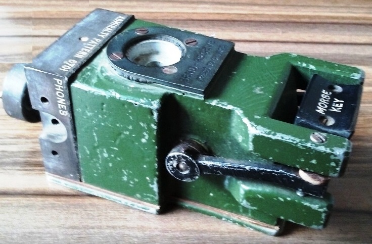 |
| Morse key for type 53 receiver/transmitter. (Photo by Clive Kidd) |
| 60 Series Transmitters
In the RCN, the type 60 was used primarily on 2410 kcs in low power, voice mode during convoy duty and local harbour operations.It is likey that only HMC ships Haida, Athabaskan, Iroquois were fitted with the 60 series transmitter system. These ships were fitted with UK electronics on build. 724A Absorption Wave Meter Typically, it was issued one per destroyer or one for a group of corvettes and was used to check the accuracy of transmitting frequencies. It's frequency range was 16 kc to 50 Mc. 86M Type (SCR 522 Equivalent) A voice only, crystal controlled transmitter operating in the 100 to 156 Mc band with a power input of 8 to 9 watts. This was the British version of the SCR 522 set. It could operate from a 230 VAC 50 Hz power main or 24 VDC supplied by a battery. In January of 1944, when HAIDA was transferred to Plymouth Command, an 86M remote control was installed on the bridge and was used for voice communications. When communicating with aircraft, a range of 120 miles could be realized if the aircraft was flying at 10,000 feet. According to Geoff Mason of Bristol England, "the original 86M fitting in Royal Navy ships used 24 VDC to feed a standard aircraft dynamotor. In late 1945, a 230 VAC power unit (SE8) was developed and became the standard fit for the 86M in all ships and submarines. In the first fittings, the configuration of the 86 set was a straight copy from that of an aircraft. Later, the 86M set permitted the use of the standard RN microphone/headset socket. Initially, the set and the frequency controller were fitted on the bridge but after the war, the controller was moved to the Operations Room. The first aerials, fitted between 1942 and 1944, were mounted on the end of the yardarm in the vertical plane and fed by co-ax. This co-ax was cut back at the aerial end to expose the center conductor for a length suitable for the frequency band to be used, thus forming the active element. The copper braiding was then unwoven and formed into two counterpoises. This handiwork was then secured to a wooden 'cruciform' structure which provided supporting strength and was mounted vertically on the end of the yardarm. Two of these antennas were fitted per ship and one or the other would be selected depending from which side the approaching ship or aircraft was coming. By 1943, a standard aerial outfit (ARD) was introduced into service and was mounted on an extension bar fitted to the yardarm end so as to provide a better line of sight. Only one ARD aerial was fitted for each 86M set. The 'sword' type of aircraft aerials were never observed on RN ships but may have been used on smaller craft such as rescue launches". Harold Dixon of Minooka Illinois served as a Sparker aboard HMCS HAIDA. He recollects using the 86M set. "The only time it was used was during action stations when engaging the enemy. My operating position was on the port side of the bridge, just below the "step". In that position during action stations, my head just came up to the glass where I could see in all directions. There in the operating position, I had used both straight key CW and VHF voice. I used split ear phones with CW in one and VHF in the other. CW was the main communications method and it was used by the CO of the destroyer flotilla to issue orders. Those orders were quick command signals like Blue Nine for 90 degrees (right turn etc..) In fact, another HAIDA Sparker, Jack Raine, was usually the operator in the radio office that keep me on frequency. As far as VHF goes, I could put that on the speaker for "Hard over Harry" to hear (Harry DeWolf, HAIDA's CO in 1944). The VHF radio was right there so he could use it at any time. Commander Dewolf was quite a guy. At sea, I had to stand at my action station for long periods of time. In the North waters it was darn cold, and everyone battled fatigue so it was very easy to fall asleep. I did it once but not for a long because I got a good kick from good old "Harry". He said "sailor keep awake" and boy it never happened again". In the mid 1940's, the 86M was removed and HAIDA was fitted with the SCR 522. The following standard RCN
crystal frequencies were available for the 86M transmitter: even if
it was very obsolete in 1963. It was the same deal for the receiver,
|
 |
| On G89, HMCS Iroquois, the 'crucifixes on the end of the lower yardarm are the antennas for the British 86M VHF set. Later on in the war, the 86M set was standardized to use aerial outfit ARD. (RCN photo provided by Darren Scannell) |
| 89 Type Transmitter
|
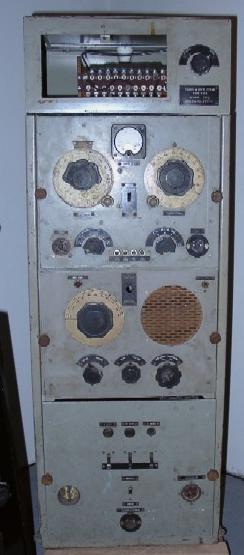
In the Main Office, all operating bays were made from steel frames bolted to the deck. Equipment was mounted on an operators 'bench' (the work surface) and each of the six operating positions had a swivel bucket seat, bolted to the deck. In addition, there was a MF/DF bay. Fitted in this room, were two LF/MF receivers, the old CN unit (MF/LF Rx) plus two high frequency transmitters and receivers and later, a B28 receiver. The majority of the floor space was taken up by an MF transmitter enclosed in a wire cage. Some Tribals were equipped with an HRO receiver in addition to the original Admiralty equipment. An emergency receiver, using a 20 VDC power source, was fitted in the main office. All other equipment was powered from AC mains. As I recall, there was also a Type 73 or 74 (presumably UHF) transmitter-receiver, apparently a new model at the time. Its main use was to signal manoeuvring instructions. In the Secondary Office, there were two operating positions each facing the side of the ship. When the sound proof door was closed, the only means of communication with anyone was the voice powered telephone. When I joined HMS SOMALI in 1940, we had a DF office on the flag deck which housed the FH3 DF receiver. In 1941, it was removed in order to make way for our first radar set". |


 This was a four band Loran A receiver of U.S. origin and was designed to
receive signals in the 1.7 to 2.075 and 9.9 to 12.1 Mc bands. Power consumption
was 240 watts from a 120 VAC 2.7 ampere source. The Loran radio system
was used to establish the position of a ship or aircraft. It consisted
of a master and one or more slave stations. The master station emitted
a short pulse or signal, which was repeated by the slave station. These
pulsed, synchronized transmissions were received aboard ship or aircraft
and recorded on the screen of an oscilloscope built into the Loran receiver.
By reading the time difference of the signals between one pair of stations
and those of another pair, the position of the ship or aircraft was found
at the intersection of hyperbolic curves printed on a special chart. Today,
Loran A is obsolete having been replaced by Loran C, and a satellite navigation
system such as GPS.
This was a four band Loran A receiver of U.S. origin and was designed to
receive signals in the 1.7 to 2.075 and 9.9 to 12.1 Mc bands. Power consumption
was 240 watts from a 120 VAC 2.7 ampere source. The Loran radio system
was used to establish the position of a ship or aircraft. It consisted
of a master and one or more slave stations. The master station emitted
a short pulse or signal, which was repeated by the slave station. These
pulsed, synchronized transmissions were received aboard ship or aircraft
and recorded on the screen of an oscilloscope built into the Loran receiver.
By reading the time difference of the signals between one pair of stations
and those of another pair, the position of the ship or aircraft was found
at the intersection of hyperbolic curves printed on a special chart. Today,
Loran A is obsolete having been replaced by Loran C, and a satellite navigation
system such as GPS.

 See description in HAIDA Radio 4 section.
 This was a marine radiotelephone whose superheterodyne receiver tuned two
bands: 550 kc to 1700 kc and 2000 kc to 3000 kc. Output power was 12 watts
and the transmitter could be controlled with a foot switch. On transmit,
one of three crystal controlled frequencies between 2000 kc to 3000 kc
could be selected. Power could be supplied from either a 6 or 12 VDC source
depending on the model of the power supply. The HT11 was manufactured by
the Hallicrafters Company of Chicago. Operators used it for communications
between ships equipped with HF/DF installations. Ted Burke of Ottawa,
Ontario was a Sparker during WWII and he recalls a few things about the
HT11. "The HT-11, a battery operated MF R/T set, was usually found in the
HF/DF office where it provided communication between a flotilla's "Huff-Duffers".
It was fitted with a chest microphone and a foot operated on/off pedal
so that the operator could be taking D/F bearings while talking.
I knew this gear well because mine was hooked up backwards to the battery
and its charging circuit so much so that we could never got to sea without
it failing at once to the bewilderment of the Londonderry Port Wireless
Officer to whom I complained after each trip. Finally, the HT-11
was yanked out and replaced with the TCS, a superior AC powered CW and
RT set with enormous range. It should not be confused with the TBS VHF
set which was used for communications between escorts and remote controlled
by the bridge. We actually had two TCS sets fitted in HMS NESS K219,
a River-class frigate. Inexplicably, one was installed in the starboard
mine-sweeping flat where the salt air rusted it badly! Mine got me
through the war nicely.
This was a marine radiotelephone whose superheterodyne receiver tuned two
bands: 550 kc to 1700 kc and 2000 kc to 3000 kc. Output power was 12 watts
and the transmitter could be controlled with a foot switch. On transmit,
one of three crystal controlled frequencies between 2000 kc to 3000 kc
could be selected. Power could be supplied from either a 6 or 12 VDC source
depending on the model of the power supply. The HT11 was manufactured by
the Hallicrafters Company of Chicago. Operators used it for communications
between ships equipped with HF/DF installations. Ted Burke of Ottawa,
Ontario was a Sparker during WWII and he recalls a few things about the
HT11. "The HT-11, a battery operated MF R/T set, was usually found in the
HF/DF office where it provided communication between a flotilla's "Huff-Duffers".
It was fitted with a chest microphone and a foot operated on/off pedal
so that the operator could be taking D/F bearings while talking.
I knew this gear well because mine was hooked up backwards to the battery
and its charging circuit so much so that we could never got to sea without
it failing at once to the bewilderment of the Londonderry Port Wireless
Officer to whom I complained after each trip. Finally, the HT-11
was yanked out and replaced with the TCS, a superior AC powered CW and
RT set with enormous range. It should not be confused with the TBS VHF
set which was used for communications between escorts and remote controlled
by the bridge. We actually had two TCS sets fitted in HMS NESS K219,
a River-class frigate. Inexplicably, one was installed in the starboard
mine-sweeping flat where the salt air rusted it badly! Mine got me
through the war nicely.
 Made by Marconi in the early 1940's, this was a four tube, low/medium frequency
regenerative receiver, operating in the 15 to 1550 or 15 to 1775 kc band
depending on the variant. This receiver required an external battery supply
(90 VDC plus 6 VDC) which was connected to chassis mounted binding posts.
Since there was no audio output stage, earphones were required for normal
operation. Stations were tuned in by operating two separate tuning controls
and two non-ganged range switches. For CW reception, a 1440 Hz note filter
was used. One unique feature in this design, was a self-contained crystal
radio. Until the early 1950's, it was a requirement of the British Merchant
Shipping (Wireless Telegraphy) Rules that the radio installation aboard
a British registered vessel should be capable of 'maintaining reception
by means of a rectifier of the crystal type'. Subsequent modification of
these rules required the installation of a separate emergency or reserve
receiver.
Made by Marconi in the early 1940's, this was a four tube, low/medium frequency
regenerative receiver, operating in the 15 to 1550 or 15 to 1775 kc band
depending on the variant. This receiver required an external battery supply
(90 VDC plus 6 VDC) which was connected to chassis mounted binding posts.
Since there was no audio output stage, earphones were required for normal
operation. Stations were tuned in by operating two separate tuning controls
and two non-ganged range switches. For CW reception, a 1440 Hz note filter
was used. One unique feature in this design, was a self-contained crystal
radio. Until the early 1950's, it was a requirement of the British Merchant
Shipping (Wireless Telegraphy) Rules that the radio installation aboard
a British registered vessel should be capable of 'maintaining reception
by means of a rectifier of the crystal type'. Subsequent modification of
these rules required the installation of a separate emergency or reserve
receiver.
 This was a ship-to-shore transmitter. See description in the Radio 2 section.
Sitting on top of the transmitter is the dummy load which is comprised
of four 150 watt light bulbs.
This was a ship-to-shore transmitter. See description in the Radio 2 section.
Sitting on top of the transmitter is the dummy load which is comprised
of four 150 watt light bulbs.  The PV500 LM transmitter was a CW only unit operating in the frequency
range of 100 to 500 kc. It had a rated power input of 500 watts and frequency
control was by master oscillator (M.O) only. There were four switch selectable
M.O's in total and they were pre- set to the four most popular operating
frequencies. Since inductors and capacitors that operate in the low frequency
band are rather large in physical size, they were not enclosed in the same
cabinet as the PV500 proper. Instead, they were mounted external to the
transmitter and shielded with a wire cage. The entry to the cage was interlocked
and power would be disconnected if the door was opened. A PV500 LM was
fitted on HMCS HAIDA during the 1940's.
The PV500 LM transmitter was a CW only unit operating in the frequency
range of 100 to 500 kc. It had a rated power input of 500 watts and frequency
control was by master oscillator (M.O) only. There were four switch selectable
M.O's in total and they were pre- set to the four most popular operating
frequencies. Since inductors and capacitors that operate in the low frequency
band are rather large in physical size, they were not enclosed in the same
cabinet as the PV500 proper. Instead, they were mounted external to the
transmitter and shielded with a wire cage. The entry to the cage was interlocked
and power would be disconnected if the door was opened. A PV500 LM was
fitted on HMCS HAIDA during the 1940's. The Hallicrafters S27 was designed in 1940 and covers 27 Mcs through 143
Mhz for the reception of AM, CW and FM signals using three bands. Its original
cost was $US 175. Key features of the design were the use of mil-spec components
and wiring, no electrolytic capacitors, and heavy duty chassis with strong
internal bracing. The tuner is a separate, removable chassis, and uses
acorn tubes. Specifically, the set incorporates the following : an IF of
5250 Kc; a Foster-Seely FM discriminator; a switchable 'narrow' and 'broad'
IF bandpass; and a push-pull 6V6 audio amplifier stage. Another variant
of the receiver, the S27B, was made between 1940 and 1941. Its frequency
range covered 36 to 165 Mcs. Production of the S27 continued from 1940
to 1943 when it was replaced by the by S-36. S-36/36A began production
in
1942 and covered 27.8 to 143 Mcs. From an electrical viewpoint, the replacement
model was virtually identical except for some tube changes in the audio
section. Many S27's were used during World War II as countermeasures receivers.
The S27 used aboard HMCS HAIDA was known as the 'Headache Receiver'.
The Hallicrafters S27 was designed in 1940 and covers 27 Mcs through 143
Mhz for the reception of AM, CW and FM signals using three bands. Its original
cost was $US 175. Key features of the design were the use of mil-spec components
and wiring, no electrolytic capacitors, and heavy duty chassis with strong
internal bracing. The tuner is a separate, removable chassis, and uses
acorn tubes. Specifically, the set incorporates the following : an IF of
5250 Kc; a Foster-Seely FM discriminator; a switchable 'narrow' and 'broad'
IF bandpass; and a push-pull 6V6 audio amplifier stage. Another variant
of the receiver, the S27B, was made between 1940 and 1941. Its frequency
range covered 36 to 165 Mcs. Production of the S27 continued from 1940
to 1943 when it was replaced by the by S-36. S-36/36A began production
in
1942 and covered 27.8 to 143 Mcs. From an electrical viewpoint, the replacement
model was virtually identical except for some tube changes in the audio
section. Many S27's were used during World War II as countermeasures receivers.
The S27 used aboard HMCS HAIDA was known as the 'Headache Receiver'. The SCR 522 was a voice only, transmitter/receiver operating in the 100
to 156 Mc bands with a power input of 8 to 9 watts. It was re-design of
the British TR 1133 VHF set in order that it could be manufactured with
American tooling. Operation was provided on any one of four crystal controlled
channels. Integrally mounted in a common case, was the BC624A VHF receiver
and the BC 625A VHF transmitter. The rest of the system consisted of 28
VDC input dynamotor (PE-94-A) and various jack and junction boxes. Input
power consumption was 311 watts. Transmitter channel 'D' was sometimes
used in 'pipsqueak' mode. Pipsqueak was a homing or DF tone sent from the
aircraft to a ground station so the ground station could take bearings
on the aircraft. It was useful either for normal DF work or when the aircraft
was in trouble and the pilot did not want to stay around to transmit. There
was a "contactor" unit BC-608-A located on the aircraft instrument panel
which looked like a clock and had a spring wound with a knob. When activated,
the contactor keyed the '522 for about 15 seconds in each one-minute period.
Normally, the SCR 522 was fitted into aircraft, however, in this instance,
it was a case of the navy adopting a piece of equipment from another service
for it's own use. It was also used by the British Air Ministry and the
U.S. Army Signal Corps. In the RCN, the SCR 522 (in the form of the Model
86M) was used for inter- ship voice communication. If the SCR 522 was operated
with the PE-98 dynamotor unit (14 VDC), the SCR 522 was designated as SCR
542. Both sets were identical in all other respects.
The SCR 522 was a voice only, transmitter/receiver operating in the 100
to 156 Mc bands with a power input of 8 to 9 watts. It was re-design of
the British TR 1133 VHF set in order that it could be manufactured with
American tooling. Operation was provided on any one of four crystal controlled
channels. Integrally mounted in a common case, was the BC624A VHF receiver
and the BC 625A VHF transmitter. The rest of the system consisted of 28
VDC input dynamotor (PE-94-A) and various jack and junction boxes. Input
power consumption was 311 watts. Transmitter channel 'D' was sometimes
used in 'pipsqueak' mode. Pipsqueak was a homing or DF tone sent from the
aircraft to a ground station so the ground station could take bearings
on the aircraft. It was useful either for normal DF work or when the aircraft
was in trouble and the pilot did not want to stay around to transmit. There
was a "contactor" unit BC-608-A located on the aircraft instrument panel
which looked like a clock and had a spring wound with a knob. When activated,
the contactor keyed the '522 for about 15 seconds in each one-minute period.
Normally, the SCR 522 was fitted into aircraft, however, in this instance,
it was a case of the navy adopting a piece of equipment from another service
for it's own use. It was also used by the British Air Ministry and the
U.S. Army Signal Corps. In the RCN, the SCR 522 (in the form of the Model
86M) was used for inter- ship voice communication. If the SCR 522 was operated
with the PE-98 dynamotor unit (14 VDC), the SCR 522 was designated as SCR
542. Both sets were identical in all other respects.
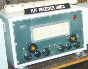 A receiver operating in the 97 to 30000 kc range and used for the reception
of shore based broadcast messages.
A receiver operating in the 97 to 30000 kc range and used for the reception
of shore based broadcast messages. 

 This LF/HF transmitter was manufactured by Westinghouse Electric in the
United States and was generally available after 1944. Contracts were also
awarded to General Electric and RCA. It was fitted in the main radio office
where it used exclusively to provide ship to shore communication and was
operated from a position in the same office. Many Telegraphists still remember
that 'big black box' in the radio office. The cabinet measured 72" high
by 32 inches wide and weighed 804 pounds. In the TBL, only two tube types
were used. The type 860 tetrode was used for the master oscillator, doublers
and driver amplifiers while the RF stage employed a pair of 803 tetrodes.
This LF/HF transmitter was manufactured by Westinghouse Electric in the
United States and was generally available after 1944. Contracts were also
awarded to General Electric and RCA. It was fitted in the main radio office
where it used exclusively to provide ship to shore communication and was
operated from a position in the same office. Many Telegraphists still remember
that 'big black box' in the radio office. The cabinet measured 72" high
by 32 inches wide and weighed 804 pounds. In the TBL, only two tube types
were used. The type 860 tetrode was used for the master oscillator, doublers
and driver amplifiers while the RF stage employed a pair of 803 tetrodes.
 The TBS series of VHF MCW/RT transmitter/receiver were manufactured between
1938 and 1944 by RCA Victor, Camden N.J. Specifically, the model TBS-6
was released on Aug 25, 1943. This set covered the 60 to 80 Mc range with
a power input of 50 watts. Frequency control of both the transmitter and
receiver was accomplished by crystal control. The operators who used these
sets adopted the unofficial name 'Talk Between Ships'. Since the TBS operated
in a line-of-sight range, a belief prevailed that it was impervious to
enemy interception, however, its use in the RCN was restricted to that
of convoy duty during the war. Using the TBS in harbour was prohibited.
Power to operate the TBS was derived from motor-generator sets. Primary
power for these M-G sets was obtained from a variety of D.C. or A.C. sources,
depending on what was fitted on a particular ship. The chief differences
in the various TBS models were determined by the particular M-G set that
powered the unit. Of special interest, is the TBS transmission line. It
was a concentric, 3/8 inch diameter, soft copper transmission line having
an impedance of 70 ohms. To purge the transmission line of entrapped air
or moisture laden gas, the operator would open the valve on a 2000 psi
nitrogen bottle and pressurize the transmission line to a maximum of 20
psi. The antenna fitted on destroyers was a quarter wave vertical with
four horizontal rods to form a ground plane.
The TBS series of VHF MCW/RT transmitter/receiver were manufactured between
1938 and 1944 by RCA Victor, Camden N.J. Specifically, the model TBS-6
was released on Aug 25, 1943. This set covered the 60 to 80 Mc range with
a power input of 50 watts. Frequency control of both the transmitter and
receiver was accomplished by crystal control. The operators who used these
sets adopted the unofficial name 'Talk Between Ships'. Since the TBS operated
in a line-of-sight range, a belief prevailed that it was impervious to
enemy interception, however, its use in the RCN was restricted to that
of convoy duty during the war. Using the TBS in harbour was prohibited.
Power to operate the TBS was derived from motor-generator sets. Primary
power for these M-G sets was obtained from a variety of D.C. or A.C. sources,
depending on what was fitted on a particular ship. The chief differences
in the various TBS models were determined by the particular M-G set that
powered the unit. Of special interest, is the TBS transmission line. It
was a concentric, 3/8 inch diameter, soft copper transmission line having
an impedance of 70 ohms. To purge the transmission line of entrapped air
or moisture laden gas, the operator would open the valve on a 2000 psi
nitrogen bottle and pressurize the transmission line to a maximum of 20
psi. The antenna fitted on destroyers was a quarter wave vertical with
four horizontal rods to form a ground plane.
 The TV5 was an emergency transmitter/receiver made by Marconi was located
in a ship's main radio office. It was remotely operated by Morse key or
voice. This set provided communications with other ships or aircraft depending
on operational requirements but its availability for Fleet destroyers was
very unlikely in the years of 1943 and 1944. In some ships, the TV5 might
have been fitted into the second wireless office.
The TV5 was an emergency transmitter/receiver made by Marconi was located
in a ship's main radio office. It was remotely operated by Morse key or
voice. This set provided communications with other ships or aircraft depending
on operational requirements but its availability for Fleet destroyers was
very unlikely in the years of 1943 and 1944. In some ships, the TV5 might
have been fitted into the second wireless office.
 This was a 250/350 watt, AM/CW transmitter which operated in the range
of 2200 Kcs to 20 Mcs and patterned after the American- built, RCA type
ET4336. Minor modifications, incorporated in 1944 and 1945, extended the
lower frequency range down to 1500 Kcs and also provisioned an input for
a frequency shift keyer. The variants in this family were the -M, -P and
-Q. Frequency control was crystal or VFO and the type 89 was designed to
work into a single wire antenna or a whip. (HMCS Sackville was specifically
fitted with this transmitter type).
This was a 250/350 watt, AM/CW transmitter which operated in the range
of 2200 Kcs to 20 Mcs and patterned after the American- built, RCA type
ET4336. Minor modifications, incorporated in 1944 and 1945, extended the
lower frequency range down to 1500 Kcs and also provisioned an input for
a frequency shift keyer. The variants in this family were the -M, -P and
-Q. Frequency control was crystal or VFO and the type 89 was designed to
work into a single wire antenna or a whip. (HMCS Sackville was specifically
fitted with this transmitter type).