 |
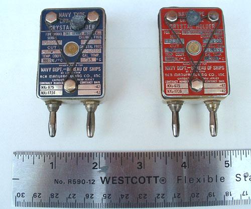
| Examples of receive and transmit crystals. These crystals were donated to HMCS HAIDA by John Forster. (Photo by Jerry Proc) |
These crystals were used in TBS transmitter/receiver equipment. Although not easily seen, these crystals used a ceramic holder. The holder was also made with bakelite.
|
| Examples of receive and transmit crystals. These crystals were donated to HMCS HAIDA by John Forster. (Photo by Jerry Proc) |
 |
|
|
Dimensions: 1.5 in wide x 2 1/8 in high x 0.75 in thick.
Holder material = ceramic or bakeliteBlue example above = 65.340 MHz receive.
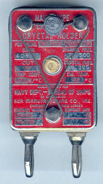
Red example above = 72.500 MHz transmit.The crystals are truly of battleship-grade construction and even includes anti-tampering wire. A piece of stranded wire threads its way through three holes in the cover screws. The loose ends are then sealed with lead seal which bears the letters RCA. Within the triangle formed by the wire, there is putty like material with the letter V embossed. This is the factory sealed adjustment which allows the crystal to to trimmed to the exact operating frequency.
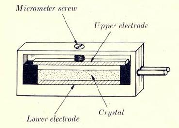
This diagram illustrates the principle of the frequency adjusting screw of a crystal. (Image courtesy RCN)
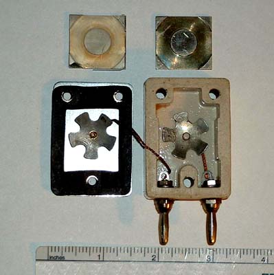 |
| This is the how the frequency adjustment mechanism looks in a crystal. The spoke-like springs connect to the banana jacks with braided wire. The holder's cover is the part at the left. (Photo by Jerry Proc) |
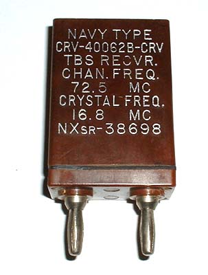 |
| TBS crystal - USN Navy type in bakelite holder. Donated to HMCS HAIDA by John Forster. (Photo by Jerry Proc) |
The late Alan Rosenthal was a design engineer with Motorola Canada. He adds further insight into crystal construction:"The type of crystal mounting that is chosen for any particular type of crystal depends on the crystals mode of vibration. There were X-mode, A-mode, Multi-mode, Shear mode, and more. It all depends on the way the slice is cut out of the crystal block, the intended frequency and the temperature range. Every cut has its own vibration mode, as well as temperature co-efficient, and therefore its mounting requirement.
All the crystals we first put into Motorola radios were pressure mounted that is simply sandwiched between two metal plates, and mounted in a holder with or without heater and thermostat. As the frequency range went up we switched to a two-spring mounting where the crystal was held up by two springs with tiny round paper-clip-like clamps, leaving the crystal free to vibrate at its center. The silver or aluminum deposited plating on the faces of the crystal are connected to the mounting springs. These crystal were usually multimode that is vibrating at 3, 5, and in some cases 7 times the frequency indicated by the nominal thickness of the plate. The vibration mode is shear so the crystal does not have to do much flexing, but the two faces must be free to move without heavy pressure from the mounting.
So after all this, you can see that there are more ways to mount a quartz or tourmaline crystal than ways to skin a cat. So when you see resonator crystals mounted between glass or quartz edge bars, or plates with squares cut out of the center, dont be surprised. Remember that in the early days of frequency control crystal making, there was a lot of sorcery and witchcraft techniques and crystal units used to cost anywhere from $30 to $130" .
Credits and References:1) John Forster <jfor(at)quik.com>
2) BRCN 5422 Electronics Fundamentals , RCN 1952
Aug 9/22