![]()
![]()
This section focuses on technical and operational information of selected Asdic or Sonar sets. During World War II, Asdic fittings could be classified as follows:
| TYPE OF SHIP | ASDIC TYPE |
|---|---|
| Bangors | 128 |
| Corvettes | 123 |
| Cruisers | n/a |
| Fairmiles | 127D/134A/134C/134D |
| Frigates | 128 |
| River Class Destroyers | 124 |
| Tribal Class Destroyers | 144/147 |
Note, that HMCS Haida was only fitted with a few of the sets described in this section of this document. When the equipment type is applicable to Haida, a comment will be found in the text. The year of introduction is suffixed after the type number. A definitive work titled 'Seek and Strike' by Willem Hackmann lists all the British Asdic sets produced from 1918 to 1960.
John Coates recalled his first experiences with type 123 Asdic. "I commissioned the first Canadian Corvette, HMCS Chambly as the senior Asdic rating. This ship was fitted with the 123 Asdic set as were most corvettes -- primitive but reliable. Its major shortcoming was its inability to gauge the target's depth. This was a critical factor because depth charges did not cause serious damage unless they exploded within twenty feet of the hull of a submarine. Both John and Harry Carson, Ex-C.P.O. 1st Class of Dartmouth N.S. provides an excellent technical description of the 123 set."The oscillator, which operated in the 14 to 22 Kcs band, was fitted in a fixed dome and controlled from an Asdic hut mounted above the bridge. Located in the hut, were a range recorder and a compass binnacle containing a magnetic compass and a training wheel. The wheel controlled a beam of light that shone through a mask below the compass face. This beam indicated the direction to which the oscillator face was pointing. Before sailing, the operator always checked that the face of the oscillator was lined up with the light beam. This Asdic set had only one compass and indicating position and it was impossible for the Captain to keep one eye on the information from the hut while controlling the ship from the bridge. The 123 and 123A Asdic's were designed to have the operator in a standing position. With other Asdic sets, the operator had the luxury of sitting on a thinly cushioned bench.
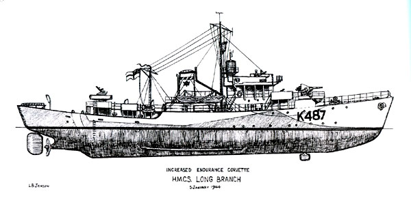 |
| The ASDIC dome on a Corvette was located just aft of the bow transition. (Drawing by Latham Jenson. From Tin Hats, Oilskins and Sabots) |
Also secured to the training wheel was a Bowden wire drive. This drive was vertically oriented and the cable passed through the navigation compartment and all other compartments directly below, until it reached the training gearbox in the Asdic well. Most Asdic ratings referred to this device as 'handraulic training'. The dome was fixed to the bottom of the keel with heavy nuts. It was covered with steel fairing plates to produce a smooth surface to reduce water noise when the ship was underway. By design, it was not necessary to house the dome as it could withstand a service speed of 18 knots, a speed that was more than the maximum speed of a corvette. When the transducer was fully lowered, its face was aligned with the Staybrite windows of the dome.
 |
| CHRONOSCOPE: Very early ASDICs did not have a range recorder. Instead,
the operator would start a 6 second stopwatch. When the initial ASDIC pulse
was heard, the watch was started. When the echo was heard, the watch would
be stopped. The range of the target would then be read from
the red scale. These stopwatches were probably made by several manufacturers
and were calibrated for salt water operation. Sound travels approximately
1,650 yds/sec in sea water.
The chronoscope could be used for ranging in event of a recorder break-down. This instrument requires the same level of care that would be given to a personal pocket watch. Waltham's Admiralty #6 Pattern , circa 1940, is one example of a company that made this product. The unit depicted here is a replica. (Image provided by Koji Kamori) |
As the oscillator expanded or contracted, the resultant sound wave was propagated through the water contained within the dome. In turn, the Staybrite window would impart the sound energy to the outer sea water. When an echo was received, the expansion or contraction of sea water warped the oscillator face accordingly. This action generated a very weak voltage in the oscillator that was applied to an amplifier and a recording device. Sending and receiving was controlled with a key or alternately with the Range Recorder. Normally, the operator pressed the key to transmit, then released it to receive. On transmission, impurities in the water would send back thousands of small echoes that were called background reverberations. When the operator no longer heard the reverberations or background noise, he would step the oscillator another 5 degrees, then press the hand key. The advice was to not to hold the key down for longer than a second, however, there was no time-out circuit to prevent it from being held down forever.The chief of the Asdic department known as the Higher Submarine Detector (HSD) would take over the set. Wearing earphones, he would direct the search and calculate the firing time for anti-submarine weapons. When the Action Station bell sounded, it was so loud it could wake the dead. In the event there was a false Action Station alarm, as happened frequently, the Asdic crew were subjected to ridicule by the other crew members. On many occasions, the alarm was the real thing. In this occurrence, everyone was pleased in knowing the Asdic ratings had their ears open while the rest of the crew slept. Off the coast of Ireland, the sea water is very pure. At times, no reverberations could be heard when steaming through this area. This caused some concern to operators who were new to the locality. Many summoned the HSD to assess the situation. In this instance, all the HSD could do is to take a look form the back of the bridge to see if there was a wake. If so, the operator was instructed to ping the wake. Much to their amazement an echo would be received from the wake but no reverberations. This procedure verified that the Asdic was operating properly."
When being hunted, some German subs used a bubble making device known as 'Pillenwerfer'. This always returned an excellent echo but there was no Doppler. It produced a perfect graph on the range recorder and there was always the temptation to depth charge the target. In practice, it was not a good idea to depth charge doubtful echoes. A smart submarine commander, with a lot a nerve, would head into the area of the depth charge explosions. He knew, that within this area, nothing could be identified on Asdic for five to ten minutes, especially if the charges had been rigged for detonation at 250 to 500 feet. A safe shelter could be had even if it was only temporary. In the 123 set, the Send/Receive key was a moving arm arrangement. When the key was pressed, a small motor was energised which then moved the arm from a receive contact to a send contact. This energized a coil and capacitor bank that, in turn, produced the pulse of electrical energy required to fire the oscillator.
If the Range Recorder was operating, the stylus would travel from the left side of the recorder face, to just beyond the point where the echo was marked on the paper. The flyback contact would engage and the stylus would move to the left side where it would engage the start contacts and another transmission would be initiated. The slope of the echo trace on the recorder paper would indicate the speed of the echo coming toward or going away from the ship. The Range Recorder Operator would slope his line of light to match the echo trace and continuously adjust the alignment until the firing bar on the opposite end of the line of light made the firing contact. This engaged the firing mechanism of the weapons system that was fitted.
 |
| The AS14 range recorder was used with the 123 ASDIC. The maximum range on this recorder was 2,500 yards. Click on image to enlarge. (Collingwood Heritage Collection) |
To change the operating frequency of the 123 set, one would have to access the transmitting panel. Mounted here, was a toroidal wound coil with a bank of capacitors in the centre. These capacitors were linked with a heavy circular bar that could be re- positioned so that it added or removed capacitors from the circuit. Moving the bar adjusted the resonant frequency of the coil/capacitor bank thus changing the output frequency. A matching transducer in the frequency range of 14 Kcs to 22 Kcs would have to be installed as each oscillator was manufactured to operate at only one frequency. Frequency co-ordination was required so that escorts guarding a convoy would not have their Asdic sets interfering with each other. The oscillator of the 123 set was composed of thin quartz crystals, cut into lengths, and then cemented and sandwiched between two circular steel plates. The thickness of the plates determined the output frequency. A subsequent technical refinement in the 123 ASDIC c produced the model 123A. The 'A' meant a minor improvement in the amplifier and the introduction of an automatic send key.If it was necessary to change a transducer, a test would be done on the dome to see if it was watertight. The nuts holding down the cover plate would be slackened off and if no water appeared, they would be removed along with the cover plate. Next, the transducer and oscillator shaft would be removed and the dome would be sealed up with a blank cover plate. After the transducer was replaced, another watertight test was performed and the procedure was then reversed.
Asdic could be used to transmit Morse code underwater. This was known as Supersonic Telegraphy (SST). It was seldom used and only between Asdic fitted ships in harbour or if a ship was exercising with a submarine. This communication was uni-directional as the sub could not reply except by sending up a flare. Morse code used in this manner was sent in plain text and was not used when engaging in submarine detection and attack procedure. When sending Morse on an Asdic set, the dots and dashes were sent much slower rate when compared to wireless. Hence, special training was required to use the SST technique. In Asdic training school, instructors frowned upon using SST since it detracted from the main purpose of the set -- to search for submarines.
Some operators were remarkable at being able to tell one echo from another. In some waters, tidal rips and temperature gradients returned Doppler echoes and sorting this out became important. If an operator played it safe by reporting every dubious echo to the bridge, he eventually lost credibility and nothing that he reported was believed. This situation never went on indefinitely as the poor soul usually asked for a transfer. It was the recruiting process at the Asdic schools that was at fault in most cases. Some people just did not have the 'ears' for Asdic work or the attention span. On Haida there was a case where the HSD requested to exchange one of the Asdic operators for a cook. In civilian life, the cook had been a typewriter mechanic that made him somewhat suitable for the job. The result was a good cook and a good operator.While in convoy, operators used Asdic to listen to the engines and propellers of other ships which was very helpful during fog conditions or on nights when everything was pitch black. To say that convoys were well protected by Asdic would be an understatement especially in the early years of the war. Typically, a convoy consisting of 30 to 50 merchant ships created a perimeter distance of 16 to 18 miles. In theory, the escorts were positioned so that their Asdic beams overlapped, providing unbroken coverage of the convoy perimeter. The reality of the situation was different. An escort group usually consisted of one destroyer and three of four corvettes, barely enough to provide proper coverage especially with Asdic whose range limits averaged around 2000 yards under normal conditions. When convoys did have sufficient escorts, not all the Asdic sets were used simultaneously. If two ships were operating in the same area and on the same frequency, there were two options. The primary option would mean shutting down one of the Asdics. Secondarily, the operating frequency could be changed. If an active set broke down, another escort ship could provide surveillance until repairs were completed.
 |
| Early ASDICs lsuch as tne type 123, had their transducers trained by a wheel mounted on the ASDIC hut binnacle. (Photo courtesy National Maritime Museum) |
123D
The improved 123 known as the 123D was developed by adding a second magnetic compass and bearing indicator on the bridge, and a loudspeaker system for the sonar operator to communicate directly with bridge personnel. The upgrade appears to have occured sometime between 1942 and 1943 for some ships, but was never fully carried out in favour of other more improved sonar sets.
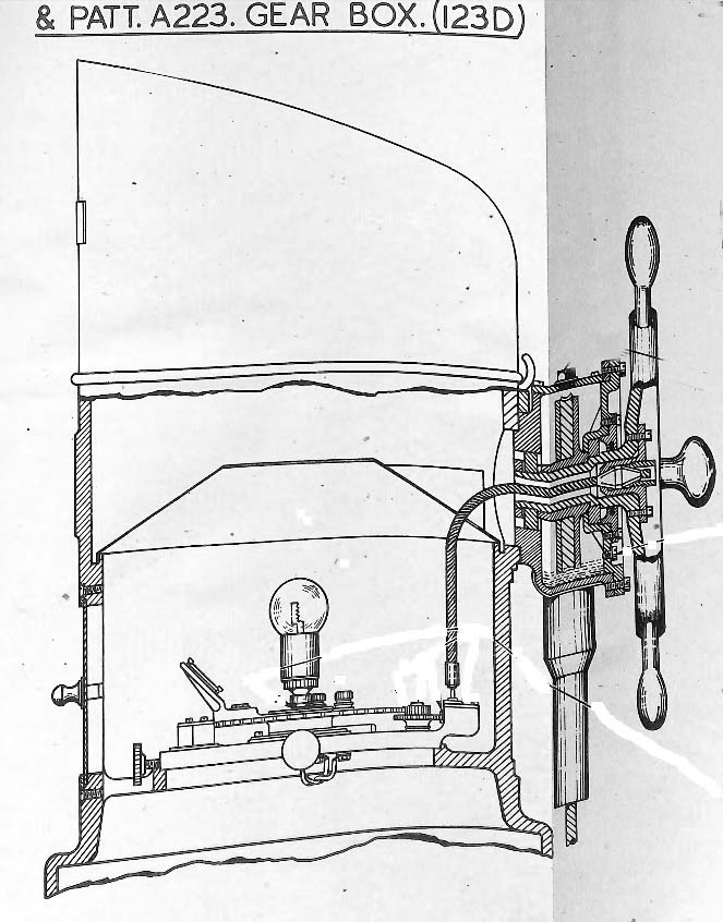 |
| Side profile of the 123D binnacle training control. The lamp would project a beam of light towars the compass rose thus indicating the bearing of the target. (Collingwood Heritage Collection |
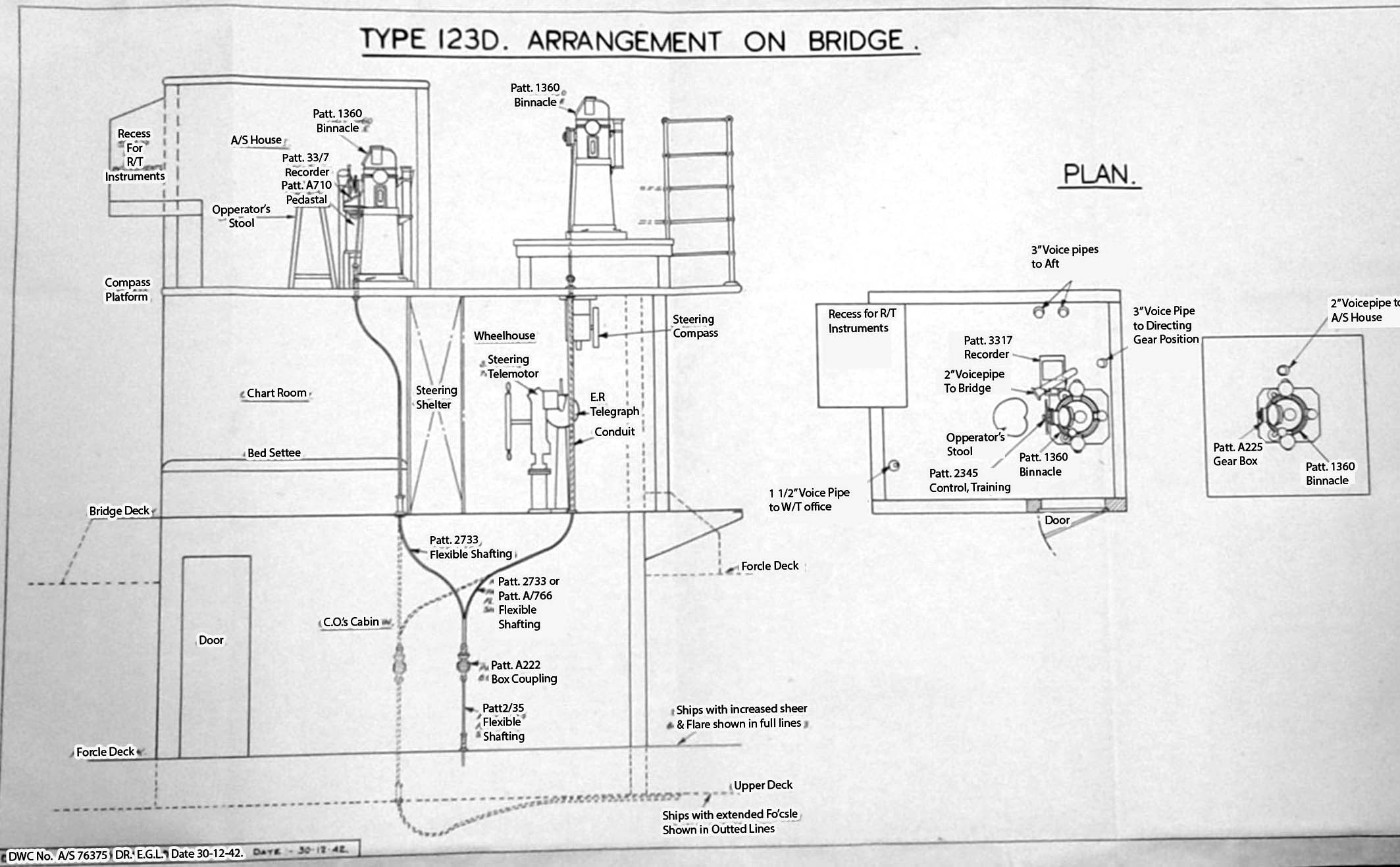 |
| 123D bridge arrangement. Click on image to emlarge. (Collingwood Heritage Collection. . Relabelled by Koji Kanori) |
Type 124 (1934-37) This set was fitted into River Class destroyers and was an updated version of the 121 set. These ships were equipped with a gyro compass thus the training mechanism was electrically coupled to the gyro. The bearing of the oscillator was indicated by a needle moving around the perimeter of a compass. Since the oscillator was driven in slave with the bridge control, it was imperative that everything was lined up before sailing. The 124 oscillator was mounted in a retractable dome.Jim Fairnie of Victoria B.C. describes Asdic operations on this type of vessel. "On some River Class destroyers, the Asdic hut was a soundproof compartment located at the aft end of the lower mess deck and was only used when cruising. Action stations were in a compartment at the aft end of the upper bridge. In other River Class destroyers, all Asdic operations were carried out from the cabin on the bridge. This was the case for HMCS Ottawa in 1945 as I was the HSD at the time."
According to Rear Admiral Bob Welland (Ret'd), this was the set used in Fairmiles. "It had two transducers fixed into a bomb shaped casing and was affixed to the ship's bottom. One transducer looked ahead and the other looked abeam on both sides. There was no backplate on the abeam transducer, so both sides of the transducer sent out the same beam. The search procedure was to use the abeam transmitters for normal search. When an echo was heard, the ship was turned to pick up the target again. There was a fifty per cent chance of turning the wrong way. When the echo was recovered, its bearing was taken and the ahead transmitter was switched on from the beam transducer. The target was then tracked by weaving to and fro across the target. Some skippers became very proficient at this manoeuvre."
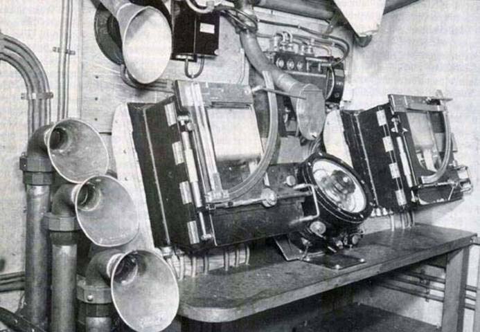 |
| 127D ASDIC. control equipment fitted in the ASDIC hut of HMCS Rimouski, November 1943. (Photo courtesy Corvettes of the Royal Canadian Navy 1939-1945). . |
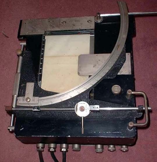 |
| Closeup of the A/S 3B Range recorder used with the 127 set. (hmsmedusa.org.uk) |
Type 128 and 128A (1937)
Frigates and Bangors were equipped with the 128 set. This was the retractable dome version of the British 127 set and was superior in performance to the 123A since it relied on a gyro compass instead of a magnetic compass for bearing indication. Priority was given for the fitting of the 128 set in Bangors because it was originally intended that their primary role was to be minesweeping, a task that required accurate navigation to mark swept channels. Corvettes, which were supposed to be jack-of-all trades -- such as escort, minesweeper, and patrol craft, would have to suffice with the less accurate 123 set which employed a magnetic compass. From 1941 and onwards, both classes of ships were transferred to ocean escort duties. It was the corvette, burdened with an older generation Asdic, that was given the task of protecting the most vital escort groups, while the Bangors served with the less important Western Local group.On Bangors, the Asdic hut was located on the forward and starboard side of the bridge. Training control was the same as that of a 124 set. In February of 1943, the British Admiralty announced that the 128 set in Royal Navy Bangors was being superseded by 128A. Type 128A had a training mechanism that was manipulated electrically rather than mechanically and was kept on target automatically by the ships gyro compass. The RCN quickly approved the same change for its own Bangors, however, it had to wait for a British policy statement before work could start. There were nineteen versions of the 128 set produced during World War 2.
This was the first defensive set and was especially suited for cruisers and other large warships such as aircraft carriers. For example, take a cruiser. Due to its size and speed, it could not alter course within the turning circle of a submarine so the installation of Asdic would be pointless. The cruiser's main defence was speed. In place of Asdic, the cruiser was fitted with a hydrophone listening set that continually swept the sea trying to locate the hydrophone effect (H/E) from a submarine. It had a large retracting dome that operated electrically with two transducers operating independently of one another. One was used on 15 Kcs for detection and the other was used for listening on 10 Kcs. Each had its own electronics and range recorders with scales of 5,000 and 2,500 yards respectively.
H/E, or cavitation noise is produced from the motion of a turning propeller regardless of whether it is a surface vessel, a submarine or a torpedo. Cavitation noise sounds like a pulsed note and can be heard at a good range depending on the size of the propeller and the speed of rotation. For example, a torpedo produced a very high pitched and fast rotation noise. When torpedo H/E was heard, the operator would sweep back and forth rapidly across the loudest H/E and report the centre bearing and movement. The Officer of the Watch (OOW) would then alter course in an effort to present the smallest possible target to the torpedo. On escorts, if a 'bow on' attack was detected, the OOW would increase speed and carry out a depth charge attack. If the assault was 'stern on,' he would alter away until the torpedo passed from astern, then alter course to carry out a depth charge attack.On Cruisers, the procedure was slightly different. If H/E was detected, say on the forward beam, the typical tactic was to alter course, pass over the submarine, drop a pattern of depth charges, then continue on a course to clear the submarine. While doing this, information on the submarine's position would be passed to the escort who was more capable in dealing with the submarine. If the H/E was picked up aft of the beam, the cruiser would increase speed and alter away from the submarine while passing information about the submarine's position to their escort.
Bob Welland, relates some personal experience with torpedo detection. "The Asdic operators were always alert for torpedoes, and it became more important when the Germans introduced an electrically propelled model known as 'Gnat'. Its propeller noise could be heard out to a mile and the Asdic was efficient at picking it up. I always had the operator do a 360 degree listening sweep every few minutes. This sweep, with no pinging, only took about ten seconds to execute. During Haida's last convoy run to Russia, this procedure proved itself. We dodged two torpedoes, having had time to turn the ship into the Asdic detected rush-noise." After the HSD reported that the torpedoes had passed, we went on to attack the U-boat."
First introduced in 1939, the type 134 ASDIC used a hand-operated, retractable, tadpole shaped dome which could not be housed. Inside the dome were two, fixed, rubber covered transducers. The single-faced transducer faced forward while the double-faced transducer faced athwartships. This dome, pattern A400 ,consisted of a gunmetal and Staybrite steel framework covered with a Staybrite steel skin. The body was split vertically into two halves which are located by means of pins on the face of the after section which fit into corresponding holes in the forward section.Power to the set was provided by nine 12 volt batteries. The high power circuits in the set consumed 1.5 kw of power while the low power citcuits consumed 200 watts.
The 134 employed a HFMA (High-Frequency Motor Alternator) and a resonant circuit to produce the sound pulse in the 14 to 22 kHz band. Power supplies for the 134 set were the same as Type 127. Six variants were produced: 134A (1941) for motor launches; 134B (1942) which had a single trainable transducer; Type 134C (1942) which was a double-faced trainable transducer and AVC (Automatic Volume Control); Type 134E (1944) had compass stabilized training. Type 134S had a reflecting plate in the dome for echo sounding and possible use for wreck detection. Type 134F (1952) was modified to detect small objects.
In February 1945, the RCN ordered that all the type 134A ASDIC sets in the type ‘B’ Fairmiles be upgraded to either 134C or 134D models.
Type 135 A document from 1952 indicates that RCN gate vessels were equipped with Type 135 ASDIC, commonly called Harbour Defence ASDIC (HDA). This technology was developed by the Royal Navy late in WWI and was first used in 1939. The 135 set first entered service in 1942. It was a special, sea-bed mounted form of the shipborne ASDIC. The US had access to this technology and called their HDA a "Herald" - Harbor Echo Ranging And Listening Device if left on the seabed. It cases where the seabed and tides were unsuitable, the ASDIC could would be secured to the side of the ship.
The 135 set used a magnetostriction transducer operating at 15 KHz and suspended on a long shaft. The circuitry was based on the Model 758 echo sounder. A printout was provided on a type 758 synchronous recorder.
Contributors and Credits:1) Tin Hats, Oikskins and Seaboots by Latham B. Jenson. Robin Brass Studio 2000. ISBN 1-896941-14-1.
2) 134 recorder https://www.hmsmedusa.org.uk/medusa-history/special-equipment-for-d-day/
3) 134C images Alan Watson [alan(at)trinitystar.plus.com]October 23/21