286 TYPE
286 TYPE
This was the first British small ship radar developed from an airborne set, the RAF ASV Mk AII.In January of 1941, Canadian destroyers serving with Western Approaches Command were being equipped with this set. It was fitted as a stopgap measure to provide some form of radar to detect surfaced U-boats at night, assist with station keeping, coastal navigation and aircraft warning for destroyers. The 286 went into production in the summer of 1940. Although inferior to daytime optical detection, the 286 improved detection tremendously in inclement weather or at night and was the best available set in that year. An Admiralty summary in May of 1941, noted that the chief merits of this set were its availability in quantity, its compact size and the speed of installation. The chief defects of the set were low range, high top weight for small craft and a poor sense of target discrimination.
This set operated on 214 megacycles (1.4 metres) at a power output of 6 kilowatt's peak, keyed by pulses 2 microseconds in duration. Its greatest fault was a fixed antenna system which consisted of two six element Yagi antennas,. These were paired vertically to produce three broad fixed beams for surface detection and warning over 60 degrees on either bow. Since the antenna was fixed, bearing accuracy was poor but it was still possible to resolve a target to plus or minus ten degrees in spite of this. Due to the fixed antenna, the ship had to be turned to acquire a different search sector.
Sea trials indicated that the set could detect a cruiser at six to eight miles, a destroyer from four to seven miles, and a trimmed down submarine at one to one and a half miles. Range accuracy was 200 yards between 1,000 and 20,000 yards. Under actual operating conditions, a trimmed down submarine could only be detected under the most optimum of conditions.
 |
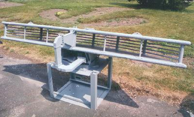
| 286 Antenna (Photo courtesy of Radar at Sea) |
Aerial outfit ATQ was a non-rotating, fixed rectangular frame, supporting a forward facing Yagi array for transmission and 2 Yagi arrays angled outwards for beamswitched reception.Type 286PQ had same the same aerial as Type 291, with only manual rotation, giving a beamwidth of 35°.
Type 286PU had one forward facing Yagi at top of mast for transmission and two angled Yagis below for beamswitched reception giving a fixed forward cover beamwidth of 140 degrees.
Type 286W/PW had a frame aerial mounted on a telescopic mast between the periscopes in submarines.
Displays: All types had 'A' scan.
Modifications: Type 286M was first operational naval version, P and Q variations had improved transmitters and directional aerials. PU was developed for trawlers and PW for submarines.
This set was the replacement for the 286 and was designed right from the beginning as naval set. It had a peak power output of 100 kw, a range accuracy of 35 yards on a 30,000 yard scale and a bearing resolution accurate to 3 degrees. Of note, was its brief service life from 1941 to 1942 before being replaced by the 291 set.
This was the final British 214 Mcs (P-Band) small ship, air search radar that was introduced in 1942. Early versions of this set required separate transmitting and receiving antennas, but a TR box was soon developed. The antenna was similar in concept to that of a 281 type, but the dipoles were supported by an X-shaped structure. This antenna had a beam width of 40 degrees and was of the lazy 'H' construction. Power output was 100 kilowatts at a pulse length of 1.1 microseconds. PRF was 500 Hz. It had the capability of detecting a bomber at 15 nm.By 1944, type 291 was fitted to nearly all British destroyers and lesser escorts. Its installation time was seven days. The M, P and Q versions had power rotation for the antenna and PPI displays in addition to the 'A' scopes. Type 291U, developed for coastal forces and trawlers, had a special lightweight aerial consisting of a pair of superimposed Yagis. It could detect a submarine at 1.5 nm. Another variant, the 291W, was designed for submarines with a rotating aerial that had to be watertight and withstand hydrostatic pressure.
The trigger unit, modulator and transmitter were engineered into a remarkably small volume by the standards of the time,and this together with the receiver units from Type 290 were packaged to form Type 291. The latter became available for operational use in 1942. It employed the rotating antenna using the newly designed aluminium pedestal, and other lightweight techniques and provided a useful air and surface warning and tracking equipment for small ships, the surface role often being enhanced by the addition of a 10-cm set. A large number were fitted in many types of small craft, from destroyers down to MTBs."
A simple A-scan display was provided with both Type 290 and Type "291. The operator had to turn the antenna by hand, and detect and track targets on the A-scan. However in April 1943 performance tests were carried out with a Type 291 fitted in Saltburn. During these trials an early model of a PPI was introduced and very brief trials conducted with it. The trials report declared the results as very promising, a very useful PPI picture being obtained. The report concluded that 'With power-driven antennae, the PPI would be useful on Type 291 for aircraft observation."
Eventually, the 291U and W sets were replaced with the model 267W. As for the 291, it remained in service in destroyers until about 1952 after which destroyer air search was restricted to coverage provided by the 293 set, the target indication radar.
Both the 291 and 293 sets were fitted on HMCS Haida simultaneously. Les Taylor of Walsall England, a former radar mechanic on Haida, recalls the details of the fitting. "The 291 office was located on the flag deck below the bridge. The antenna, which was located at the top of the foremast was fed by pyrotenax cable. This coaxial type cable consisted of a centre conductor surrounded by a powdered, ceramic-like compressed insulating material. The copper conductor and the insulation was enclosed within a hollow copper tube. If, for any reason, moisture entered the cable, its insulation properties fell below acceptable limits and required the occasional treatment with a blow torch to drive out the moisture.
Apart from these and other radar sets, I was also responsible for a new navigation aid called the QH3. It was developed by the RAF and later, its two military designers formed the DECCA Navigator Company. The QH3 was fitted while Haida was in Plymouth in 1944 and was housed in the chartroom, directly below the bridge. This set used a triangular transmission system that was reputed to fix our position to within a cable length. The QH3 became known as the QM set in the Royal Navy after 1945.
During my service on HAIDA, I was solely responsible for maintenance, range calibration, and repair of the radar equipment. There was no one that I could turn to for help, advice or to discuss technical problems. Slightly short of my eighteenth birthday, and being the youngest person aboard, I was supposed to be the expert. The technical radar school at HMS Valkyrie on the Isle of Man had many rooms containing radar equipment for either large or small ships. We were given a training choice on particular radar types that were fitted on large or small ships. Afterwards, we were drafted to those particular ships upon the completion of our training. I chose small ships. How lucky".
 |
| 291 Antenna. (Photo courtesy CB 4182/45 Radar Manual via Øyvind Garvik) |
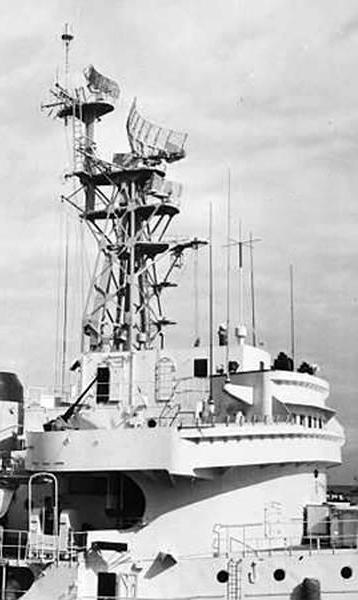
Photos of the 291 radar installation aboard HMCS HAIDA taken in February 1946.
293 TYPES
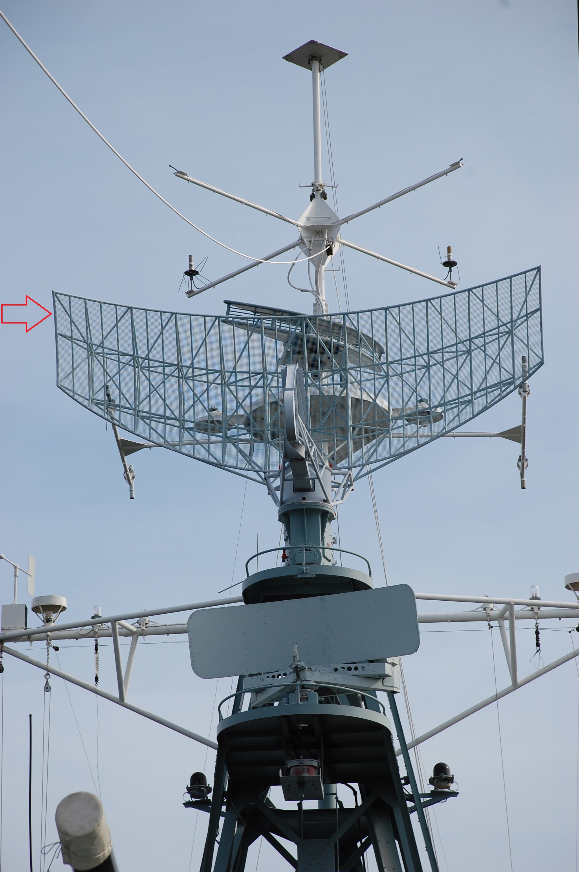
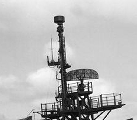
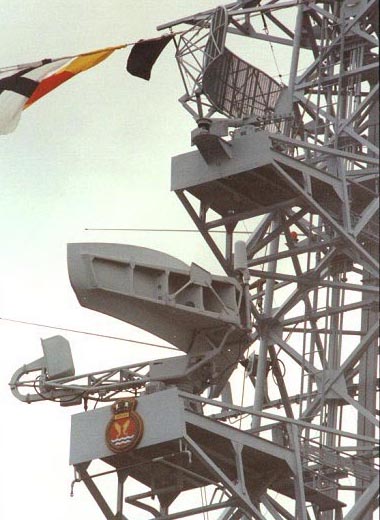
This type was an S-band target indicator (sometimes referred to as 'Warning Combined' type) using the same transmitter as the 277 type and was equipped with the new, azimuth stabilized, 'cheese' antenna. It acquired that name because it looked like a block of cheese cut in half. Stabilization was necessary otherwise, the roll of the ship would tilt the 'fanned' beam and air targets might be displayed at wildly wrong bearings. The beam was wide in the vertical plane so that the ship's roll would have little effect. Typical detection range was 15 nm for an aircraft at 10,000 feet. Type 293M, which incorporated an 8 foot antenna, was introduced into service in 1945. 293P was similar to the previous model but it was modified for easier maintenance. A post-war radar program introduced the 293Q set with a redesigned 12 foot antenna. HAIDA was fitted with the 293 type until the late 1950's.In Korea, 293 radars were operated in accordance with an Electronic Emission Control (EMC) policy. This meant that the radar could be turned on for a 3 minute duration for every 15 minute interval since the 293 was detectable by warning devices. It was assumed that the Koreans had such devices so the 293 sets were used for short periods of time only. High Definition Warning Sets (HDWS) radar was not detectable and required no such precautions.
 |
| 293 Antenna (Photo courtesy of the British Admiralty) |
| HMS Cavalier 293Q photos. |
 |
| The 293 radar system first saw service in 1944 and HMCS HAIDA was fitted with the system soon thereafter. This system was a 10 centimeter, S-band target indicator radar sometimes referred to as 'Warning Combined' (WC) type. It employed a circular, sweeping display known as Plan Position Indicator (PPI). Operating at power levels of 500 kilowatts, the radar set had a typical detection range of 15 nautical miles for an aircraft flying at 10,000 feet. (Photo by Jerry Proc) |
 |
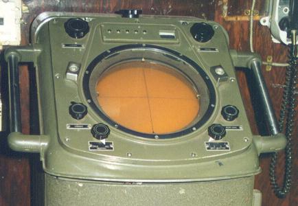
| 293 Target Indication Office. Items in this view:
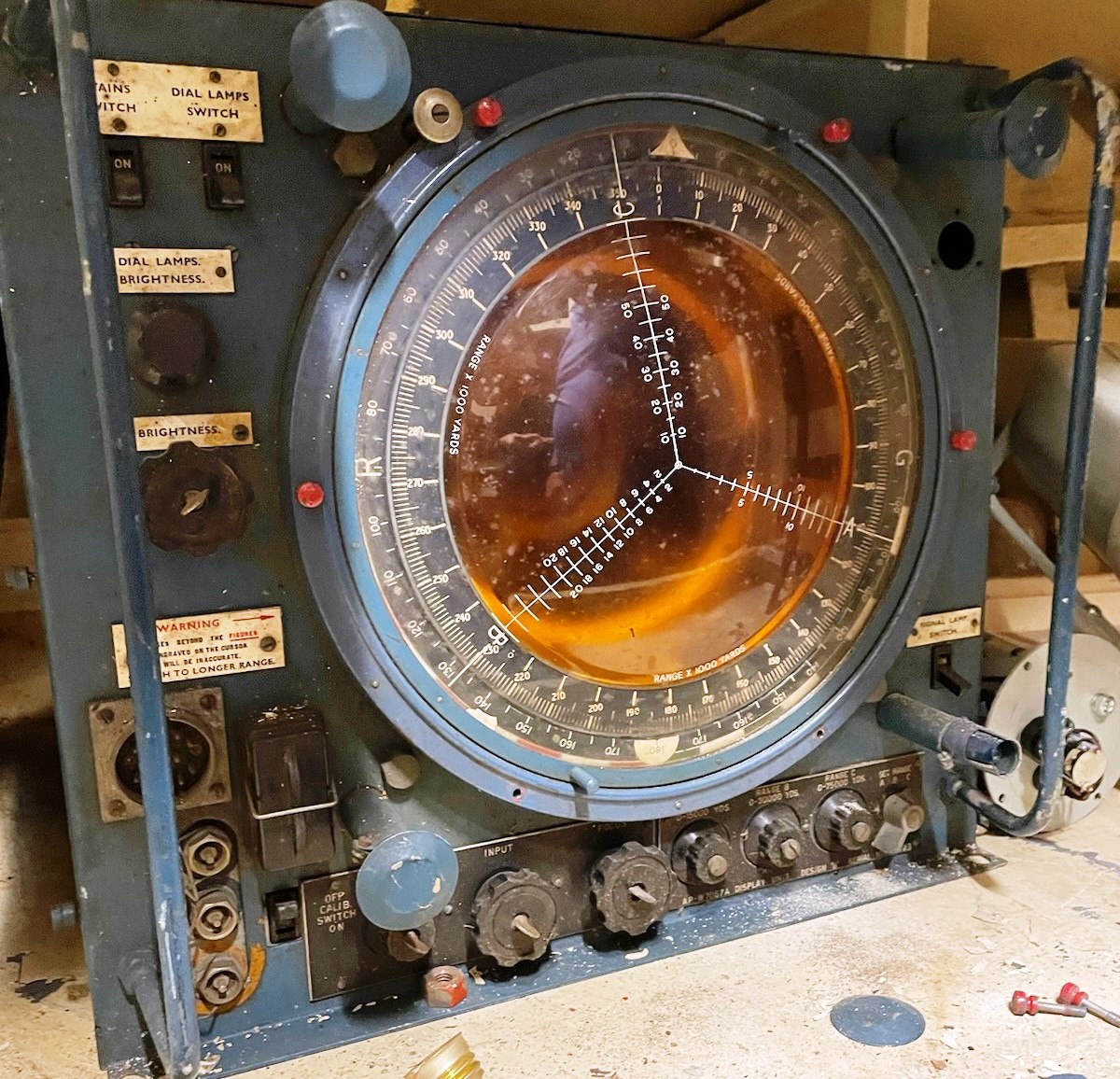
1 - PPI Display
(Photo courtesy CB 4182/45 Radar Manual via Øyvind Garvik) |
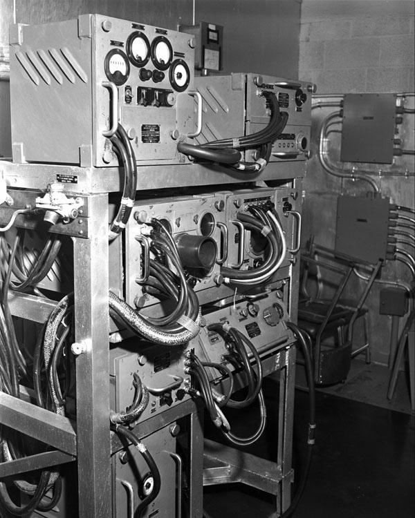
1946 Photos of the 293M Office Aboard HMCS HAIDA
 |
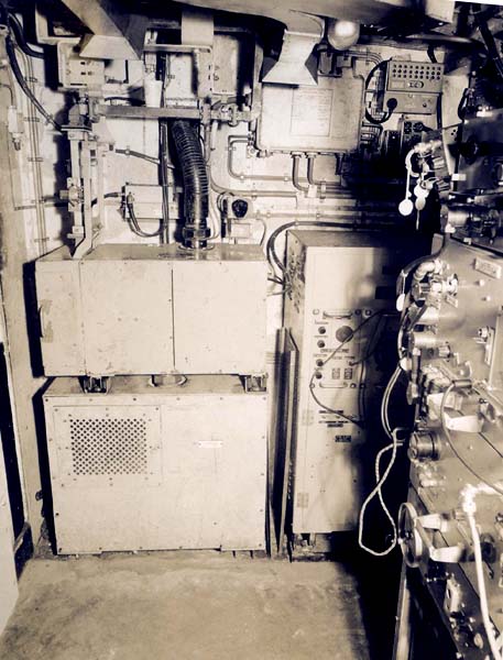
| 293M Office. Starboard bulkhead: 230 volt, 50 cycle, 3 phase power board; DUG Motor starter; Power board for DUG (180 volt, 500 cycle); Board Distributing 2-AM (RCN photo # HS1749-52) |
 |
| 293M office. After bulkhead: 293 transmitter; Output unit; P51 receiver; modulator; 253P IFF controls over modulator. On the port bulkhead, receiving panel L26; Wavemeter G82A and anti-wave clutter unit over L-26; aerial controls unit 20H below. (RCN photo # HS1749-53) |
 |
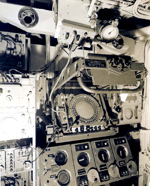
| 293M Office. After bulkhead: 293 transmitter; modulator; On the port bulkhead, 253P IFF (extreme left of photograph) 242 IFF responser, performance meter, modulator and mixer; Receiver panel L26, with wavemeter G82A and anti-wave clutter unit; AQR aerial control table (front cover removed to show control unit 20-H). (RCN photo # HS1749-54) |
 |
| 293M Office. Port bulkhead: PPI Unit; ranging outfit RTE including panel L-37 and two strobe generators; cathode follower unit is below RTE. (RCN photo # HS1749-55) |
 |
| Target Indication Room - after bulkhead.
Ranging outfit RTB including panel L-37 and two strobe generators. TIU/PPI displaying 293M; Outfit JH-1 (panel L-43); PPI control board and 242 IFF aerial indicator (over TIU). (RCN photo HS 1749-58) |
| The RCN photos in the this table came from the collection of the late John Rouey of Ottawa. |
 |
| This 293 PPI is part of the the radar system which remains in a storage area aboard the ship. Click on the image to enlarge. (Photo by Neil Bell) |
4356M BOTTLE TRANSMITTER
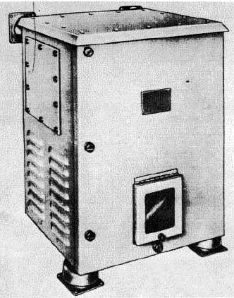
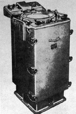
The bottle transmitter (B.T.) did not emit any radio frequencies. This device was used to provide transmission to a group of repeater motors, such as those in a radar installation, or to step up the number of repeaters that can be controlled from a gyro-compass where it is inconvenient to use a multiple transmitter or transmitter panel. They were also used extensively where it was desired to use Admiralty type equipment controlled by some other type of gyro compass.
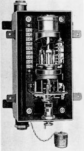 |
| Bottle Transmitter. (Photo courtesy of the British Admiralty) |
Bottle transmitters fell into two groups -- pattern #5356 that transmitted to M-type repeater motors and pattern #5355 that transmitted to Sperry-type repeater motors. The B.T. could operate a load equivalent to fifteen Mark 10 M-type repeater motors at its maximum. On HMCS HAIDA, the bottle transmitter was used to transmit azimuth information from the Admiralty Mk 5 Gyrocompass to remote indicators. This very obscure information has been posted here for lack of a suitable home.
BRCN213, the RCN's Catalogue of Materials (circa October 1961), lists a number of radar test sets that were available for the equipment which was in use at that time. Select this link to see the listings.
AN/SPA-4
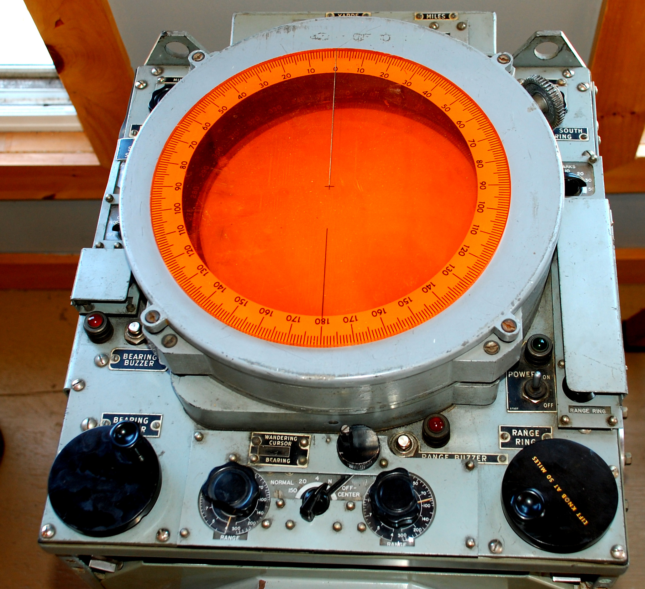
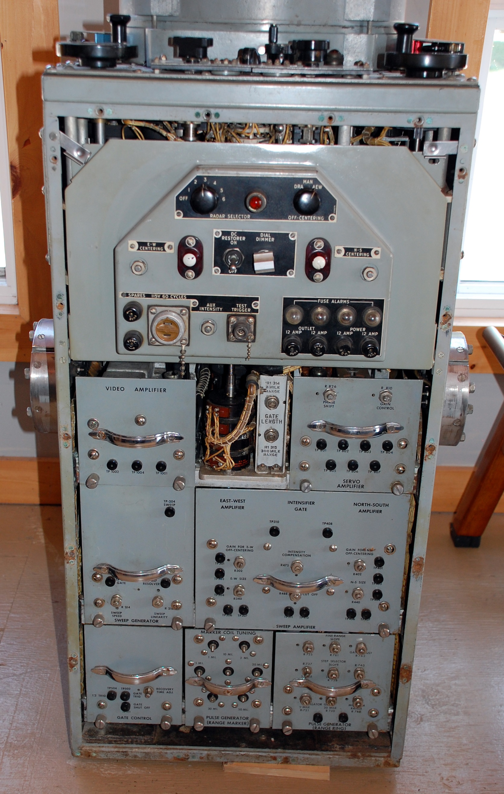
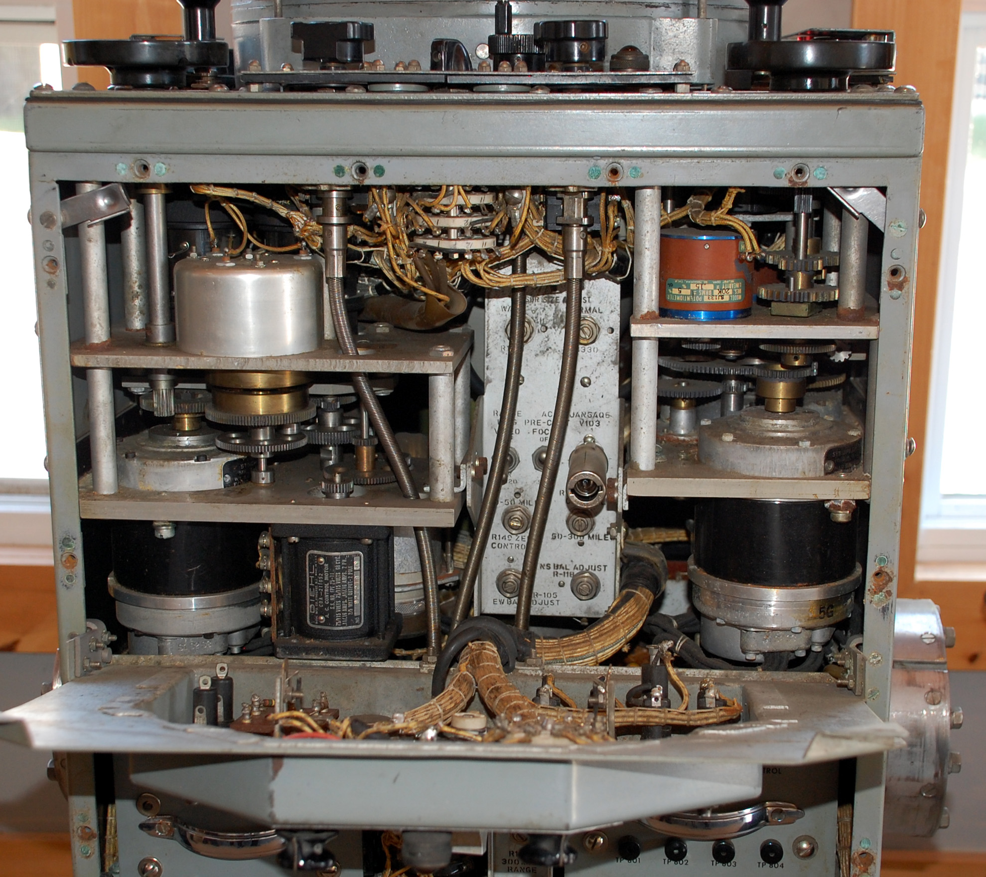
The Range-Azimuth Indicator AN/SPA-4 was a self-contained unit that was designed for operation with any naval search radar system having a pulse repetition frequency between 140 and 3,000 pps. This indicator was capable of receiving radar information from one of eight different radar systems as selected by a front panel control. This feature was not used in HMCS HAIDA but ships of succeeding classes did use it. That switch controlled a radar switchboard called the SB-440. Position 1 selected the SPS-10, 2 for SPS-12 and 3 for Sperry Mk2. On HAIDA there was an externally mounted selector switch that was used to select the radar input source. The SPA4 employed a remote PPI type indicator using a 10 inch, flat CRT.
 |
Azimuth was determined by means of a mechanical cursor coupled to an electronic cursor jointly they were accurate to within one degree. Azimuth information was also indicated by a mechanical counter when the cursor was moved. Range information was obtained from range rings that could be displayed at intervals of 0.5, 1, 2, 5, 10, 20 and 50 miles. Range could also be measured by a mechanical counter. An electronic range strobe was accurate to within 1 percent of the maximum range being viewed.The SPA-4 was also capable of transmitting electrically, the bearing and range information to other systems such as fire control or directly to a projector on the plot table. That would cut down on verbal communication.
| Range selection | 1.5 to 300 miles continuous using a centered |
| PPI and limited by the pulse rate of radar set | |
| that it was connected to. | |
| Weight | 378 pounds |
| Dimensions | 38" H x 19" W x 21" D |
| Power requirements | 120 VAC, 60 Hz at 10 amps |
| Contractor | RCA Victor Company, Montreal P.Q. |
| Contract number | FE 113375, A/T 2-P-1-1877 |
| Vintage | September 1954 |
When HAIDA was paid off, she was equipped with two AN/SPA4A units. One was located in the radar hut and the other unit was on the bridge.
Type: Radar repeater
Repetition range : 60 to 2000 sweeps per minute
Power consumption: 115 VAC 60 Hz 1200 watts.
Contractort: Hazeltine , Little Neck , NY.
 |
| Principal components of the AN/SPA-8 radar repeater (Image via US Navy) |
AN/SPA-12
The AN/SPA 12 is listed in BRCN 213, the RCN Materials catalogue. No information is available at this time.
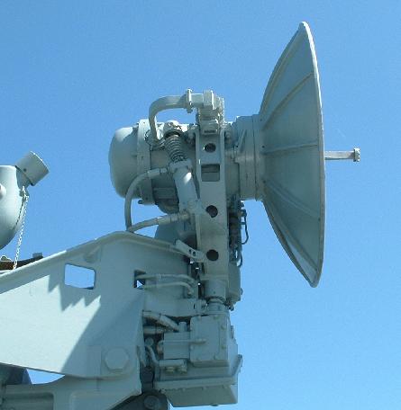
An X-band fire control radar for AA guns. The antenna was a 40 inch diameter dish that could produce a 2.4 degree beam. Power output was 25 to 30 Kw with a range of 25,000 yards. HAIDA was fitted with the AN/SPG-34 fire control radar.
 |
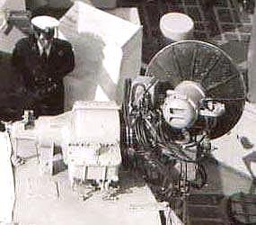 |
| AN/SPG-34 installed on Nootka's 3"50 gun. Taken in 1958. (Photo courtesy Gary Pollock) |
|
 |
|
| Side view of the SPG34 as fitted on HAIDA's 3"50 gun. (Photo by Jerry Proc) | |
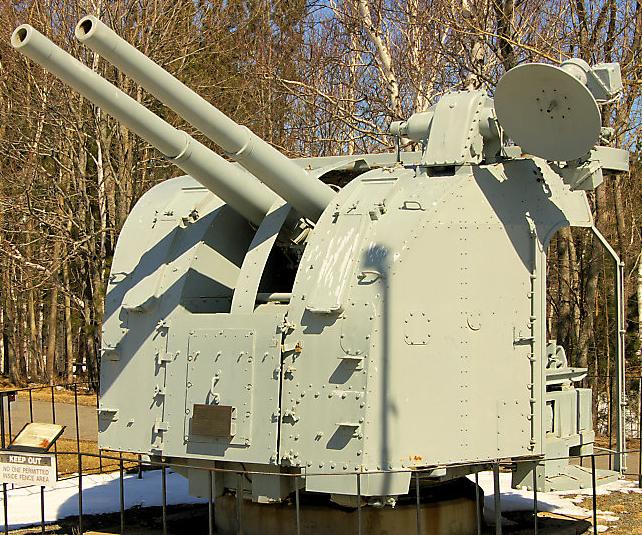 |
| Normally the SPG-34 radar was mounted on the right side of the 4 inch gun but here is a rare example of a left hand mount. This gun is located in a park in Trenton, Nova Scotia. (Photo by Sandy MacClearn) |
 |
| SPG-34 electronics. (Photo # DNS-24595 courtesy DND, Canadian Forces Joint Imagery Centre provided via by Robert Langille) |
AN/SPN-8
The AN/SPN-8 is listed in BRCN 213, the RCN's Materials Catalogue circa 1960. It is believed that this radar type might have been fitted on HMCS Bonaventure. Can anyone confirm? Contact: jerry.proc@sympatico.ca
 |
| AN/SPN-8 system pictorial. (Courtesy USN) |
The AN/SPN-8 is a Shipboard Carrier Controlled Approach System designed to guide aircraft from 6 miles out to within 400 feet of touchdown on an aircraft carrier.Specifications:
Operating frequency : 8500 to 9600 MHz
Power output: 25 Kw
Pulse rate: 400 to 4000 pps.
Antenna operation: Scans a 100 degree sector three times a second.
Antenna dimension: 14 in. high. 61 in wide.AN/SPQ-2D
An Italian designed surface search radar that could transmit both short and long pulses at the same time. It was fitted to the 280 class ships in their original configuration. The antenna was a Cosecant-squared parabolic mesh. Sometimes people associate the SPQ-2D with having two antennas. The "second antenna" in the AN/SPQ-2D radar is actually the Mk XII IFF interrogator antenna associated with that radar.This set alternated the long and short pulses, receiving the transmitted RF returns in the (PRF limited) range prior to transmitting the next alternate pulse. Short pulse was used for close-in targets (giving minimum surface ranges), while LP was for longer surface distances and the "air coverage". The advantage with this process was you either selected SP or LP, and the video for the "alternate pulse returned video" was blanked on the video channel you were looking at - so you were only looking at half the video sweeps on the PPI. The receiver also had a "Dickie Fix" setting which could be switched in or out. This was a technique developed by R.H. Dickie which reduced the possibility of overexciting an I-F strip.
The Manufacturer was Signalamento Marittemo Aero of Florence Italy. The SPQ-2 was removed in the TRUMP modernization program.
For anyone who is interested in knowing more about Dickie Fix, here is a quote from the book "Introduction to Radar Systems" by Merrill L. Skolnik, 1980, pages 549-550
Impulsive noise, that can shock-excite the narrow-band radar receiver and cause it to ring, can be reduced with the Lamb noise-silencing circuit, or Dicke fix." This consists of a wideband IF filter in cascade with a limiter, followed by the normal IF matched filter. The wideband filter is designed to include most of the spectrum of the interfering signal. Its purpose is to preserve the short duration of the narrow impulsive spikes. These spikes are then clipped by the limiter to remove a considerable portion of their energy. If the large noise spikes are not limited and are allowed to pass they would shock-excite the narrowband IF amplifier and produce an output pulse much wider in duration than the input pulse. Therefore the interference would be in the receiver for a much longer time and at a higher energy level than when limited before narrowbanding. Desired signals which appear simultaneously with the noise spike might not be detected, but the circuit does not allow the noise to influence the receiver for a time longer than the duration of a noise spike. This device depends on the use of a limiter. Limiters, however, can generate undesired spurious responses and small-signal suppression, and reduce the improvement factor that can be achieved in MTI processors. It should therefore be used with caution as an ECCM device. 1f incorporated in a radar, provision should be included for switching it out of the receiver when it does more harm than good.
The radar set AN/SPS6-C was a shipborne, long range, air and surface search type designed to supply target bearing and range data to its five inch A-scope indicator. In addition, as many as four, external, PPI indicators of the Radar Indicating Equipment VE, or Radar Repeater Equipment VJ or VK types could be attached to the SPS-6C. The RCN called this system WA meaning Warning Air. In 1947, the SPS-6 was granted AN nomenclature and the initial sets were procured from Westinghouse by the US Navy. Following quickly in 1947 were the 6A and 6B variants. The 6C and 6D versions were introduced in 1951, and the final 6E model in 1964.
|
|
|
| Frequency range | 1250 to 1350 MHz |
| Power output | 500 to 750 kilowatts |
| Pulse repetition rate | One pulse rate is 150 pps with a pulse width of four
microseconds. The other pulse rate is 600 pps with a pulse width of one microsecond. The pulse rate could be varied +/- 10 percent from each of the two frequencies given above, by means of a calibrated front panel control. |
| Receiver type | Superheterodyne type; 30 Mcs IF |
| Equipped with automatic frequency control | |
| and anti-jamming features | |
| Range markers | The 'A' scope had range markers of 4, 20, |
| 80, and 200 miles | |
| Indicator types | The system was designed to interface to |
| either VE, VF or VG type equipment | |
| Power requirements | 115 or 440 VAC, 60 Hertz at 5.5 kilowatts |
The antenna was a unidirectional, parabolic type reflector, equipped with a wind balancing vane and had a characteristic 30 degree cosecant pattern in the vertical plane. Horizontally, the beam width was 3.5 degrees. Its rotational period was 5 to 15 RPM in automatic mode and up to 2.5 rpm in manual mode. A dual feed horn on the antenna transmitted and received both radar and IFF signals. Overall weight for the antenna and its mounting pedestal was 924 pounds. The antenna itself weighed 591 pounds. Contrast that with the weight of the system cabinet which tipped the scales at 1,063 pounds.During the life of this system, there were four major American procurements. The first two were awarded to Westinghouse of Baltimore Md, the third went to AVCO Mfg/Crosley Division of Evandale Ohio and the final procurement was given to Stromberg- Carlson of Rochester, New York. Quantity and years of procurement by the RCN are not known at this time. HMCS HAIDA was fitted with AN/SPS-6C at the time she was paid off. It was originally fitted on her second tour of duty to Korea.
This image illustrates all the components of the AN/SPS-6C radar system. Click to enlarge. (Photo courtesy Westinghouse Electric Corporation)
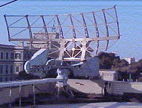
As of April 2003, this SPS6C was still employed as a research tool by the Institute of Tele- communications and Electronics of the Italian Navy in Livorno, Italy. (Photo courtesy of Alan Richardson, Eurocopter Deutschland GmbH)
For a detailed look at the SPS6-C components, please select this link. AN/SPS-10B (Modified)
The AN/SPS-10B (modified) was a medium range, C-band, good definition, surface warning set with a limited air capability. In the Canadian Forces, this type was used in pre-DELEX steamers and training facilities. It was used for the detection, ranging and tracking of surface contacts and to a limited extent, air contacts as well. Range and bearing information was passed to a PPI type display. This radar type had the potential to be used with IFF/SIF equipment so the SPS-10 was originally fitted with a built in beacon. The RCN never used this feature, so it was disabled. There never was a model SPS-10A.
SPECIFICATIONS Frequency 5450 Mcs variable to 5825 Mcs Wavelength 5 cm Peak power output Short pulse = 190 kw; long pulse = 280 kw MAximum Range 50 miles Pulse Width Short range pulse - .25 microsecond Long range pulse - 1.3 microsecond PRR 625; variable to 650 Receiver IF 30 Mcs Antenna rotation 15 rpm fixed Beamwidth Vertical - 12 to 16 degrees Horizontal 1.5 degrees Resolution On short range - 50 yds On long range - 275 yds For Bearing - less than 1 degree of error
SPS10 antenna. (Photo courtesy of http://www.fas.org) Deliveries of the SPS-10 to the USN began in October of 1953. It was considered so effective in ASW operations that 25% of all ASW vessels were fitted with this set by the end of 1956. As late as 1976, this type was described as the most reliable surface search radar with a Mean Time Between Failure (MTBF) of 150 hours and a 6 hour Mean Time to Repair (MTTR).
 |
| Labrador and Algonquin (283) were the only ships fitted with SPS-6C, SPS-10 and Sperry Mk II . In this photo, the SPS-10 is at the top, then SPS-6, then Sperry Mk II. The seven Tribals used the Type 293 instead of SPS-10. (From the collection of David Shirlaw) |
AN/SPS-12 Radar set AN/SPS-12 was an L-band, medium surveillance radar designed to detect aircraft and surface vessels. It was primarily an air search set and was fitted on the original Canadian DDE class destroyers. In some circles, it was described as an SPS-6 with much greater capability. Target range was presented on an A-type indicator. Bearing data was also provided for presentation on PPI units. Provision was also made to connect IFF equipment to the radar set.
The late Dr. H. W. Smith of the Canadian Naval Technical History Association offers some background on the SPS-12. "Perhaps surprisingly, the SPS-12 was not regarded as an improvement on the SPS-6 when first fitted in the fleet. In 1960-61, the Flag Officer Atlantic Coast and the Vice Chief of the Naval Staff (Admirals Dyer and Brock) became very concerned about the problems being experienced with fighting equipment in the RESTIGOUCHE class. The culprits named were, in order of importance: the 3-inch/70 gun, the SQS-503 sonar and the SPS-12 radar. The source for this was: Minutes and papers, 11th Senior Officers' Conference, November 20-21, 1961, file NSS 1279-188, now in the National Archives.
An investigation revealed that the radar equipment, unlike the gun and the sonar, to be blameless. The difficulty was the poor quality of maintenance in the fleet at the time. During this period one must remember that the trade structure of the Navy had been turned upside down in 1960 and electrical officers had been removed from ships, as a result of the Tisdall report. In the short run, shipboard maintenance suffered badly. Later on, the addition of a parametric RF amplifier (the Dicke-Fix receiver, developed at the Defence Research Telecommunications Establishment in Ottawa) greatly improved the performance of the SPS-12, and made it much less sensitive to mistuning then so common in the fleet".
Frequency range 1250 to 1350 Mcs Range : Instrumented max - 210 nm. 140 nm typical Wavelength 22.2 to 24 Cm Peak Power Output 500 kilowatts Pulse Length Long pulse - 4 microseconds Short pulse - 1 microsecond PRR Long range - 300 Short range - 600 (Could be varied as an anti-jamming measure) Receiver IF 30 Mcs Beamwidth Vertical - 30 degrees Horizontal - 3 degrees Antenna rotation Auto-clockwise; 2.5 to 15 rpm's Emergency - 10 rpm First delivered September 1953 Weight Antenna alone - 990lbs. Complete system (antenna, motor, waveguide, cabling, power supply, display) - 2 1/4 tons From Janes Fighting Ships:
AN/SPS-12 was developed as the king of the planned trio of early post-WWII radars: the short-range AN/SPS-3 (cancelled after one installation) and medium-range AN/SPS-6. AN/SPS-12 borrowed a lot of technology from the AN/SPS-6 and for a while early in its development was nicknamed "Super Six".
Development started in 1948 and the prototype was ready in late 1953. AN/SPS-12 had a larger antenna than AN/SPS-6 which operated at the same frequency band, but with a different beam pattern, long pulse length, and moderate repetition to achieve the best possible long-range performance. The antenna was a truncated metal parabolic mesh fed by a massive signal horn. There was no stabilization vane as the weight of the horn was sufficient. One concern of late 1940s radars was weather effects on radars following the 1945 Pacific typhoon which damaged many USN warships. Despite its size, AN/SPS-12 was guaranteed to withstand 70kt winds and could conceivably survive worse.
The operator's display was the AN/SPA-4 console which incorporated a PPI-type general display and an A-scope range-only display. AN/SPS-12 had some basic ECCM features and auto-interrogated contact IFF. As AN/SPS-6 was improved in the -6B and later versions, the difference between it and AN/SPS-12 began to shrink and thus AN/SPS-12 was built only in limited numbers. There were no real sub-versions, the -12A and -12B being cancelled with -12C simply being a fleet modification to allow third-party spare parts. AN/SPS-12 was phased out of USN service in the 1980s.
 |
| AN?SPS12 antenna . (Photo by Jerry Proc) |
AN/SPS-501
This was the AN/SPS-12 radar, adapted to the Dutch LW-08 antenna and fitted on 280 Class destroyers.AN/SPS-502
A solid state upgrade applied to the AN/SPS-10 set. It was part of the Destroyer Life Extension Program (DELEX) carried out in the early 1980's which allowed Canada's surface fleet to remain viable until the new City Class patrol frigates were delivered. At the time, it was felt that this was necessary in view of the fact that North American tube production was winding down and the only sources of new tubes were from Eastern Bloc countries - a situation which was deemed unacceptable during the Cold War!
Nipigon's foremast sports the 502 and 503 radars The upper radar is the Raytheon AN/SPS-502 surface search radar while the lower radar is the Marconi AN/SPS-503 air search radar. That's NIPIGON's badge on the SPS 503 platform . (Photo courtesy Haze-Gray site. http://www.hazegray.org) AN/SPS-502 replaced the SPS-10 in at least HMC Ships Annapolis, Nipigon, Terra Nova, Gatineau (excepting w/g, antenna, external cabling) on the east coast. All the various boxes of the SPS-10 radar system were stripped out and replaced by the one AN/SPS-502 Radar Transceiver cabinet in the Radar 1, with the remote in Ops.
The SPS-502 was a technicians dream, because of the ample space inside the cabinet when it opened up for maintenance or repairs.
AN/SPS-503 It was part of the Destroyer Life Extension Program (DELEX). See above photo, lower antenna.
The SPS-503 was a completely new radar based on the Marconi 820 air traffic control radar, slightly redesigned and marketed by Canadian Marconi as the CMR-1820. It was a maintenance-intensive radar that was poorly suited to naval applications. Its TWTs ( travelling wave tubes) failed frequently, purportedly because the transmitter was designed for the continuous operation of an airport radar system as opposed to the frequent starts/stops of a naval radar. The failure-prone combat system was the bane of the radar techs. But when it worked, it was the best long-range air search radar that the RCN had at the time.
The 503 was the Navy's first true digital TTL (tranistor/transistor logic) radar. There were literally hundreds of red LED fault indicators through out the various drawers in the cabinet and massive +5 volt power supplies. This radar allowed the Navy to gain experience on the basics of moving target indicator (MTI) techniques, signal processing and use of travelling wave tubes as the final stage output amplifiers. Antenna was provided by Plessey.
LN-16 Radar
Type: X band radar navigation radar. 9.345 to 9.405 GHz
Where used: Mainly in RCN auxiliary vessels
Power output: 7.5 kw.
Beam width: 3.5 degrees
Range: 1.5 to 20 miles
Antenna period: 22 RPM
Repetition rate: 1,000 cps
Pulse width: 0.25 µs
Overall power consumption: 600 watts.
Magmetron type: 2J42 rated from 7 to 14 kw
Alternate Magnetrons: Can be used with the British type M503 , or Sylvamia or Raytheom 2J42 magnetrons
CRT for PPI display 7 inches
Accuracy: 10% of range or 100 yards, whichever is greater.
Circa: 1950.
System cost in September 1950 : $5,975
Developed by: National Research Council
Manufactured by: Canadian Marconi
Comment:1) The LN-16 radar is listed in BRCN 213 (circa 1960) , the RCN's Materials Catalogue
No photo available at this time. If you have one, please contact: jerry.proc@sympatico.ca
2) Library and Archives Canada file number 7401-400-20 indicates that the following ships were fitted with the LN-16. radar in the 1950 time frame.
3) One of the set's features is "centre expand"
| HALIFAX BASED | ESQUIMALT BASED | |
| HMCS Revelstoke | CNAV CS Ehcoli | |
| CNAV Sackville | HMCS Cedarwood | |
| CNAV Whiterhroat | CNAV Heatherton | |
| CNAV Riverton | CNAV Dundurn | |
| CNAV Dundalk | CMAV Clifton | |
| CNAV Estore | CNAV Kaymore |
LN27 Navigation Radar This navigation radar was used on Gate vessels, Bird class patrol boats and yardcraft such as tugs LN-27 was the high power version of the LN-16
SPECS:
Wavelength: 3 cm
Power output 30 kw
Ranges: Mmimum 1 mile; maximum 14+ miles
Antenna period: ?
Total system weight: ?
Manufacturer: Canadian Marconi
Circa: 1946
Primary power input: 115 VAC at 6 amps
Comment: The LN-27 was the high power version of the LM=16 radar.
 |
| LN27 Operators Console |
 |
| Closeup of the CRT . |
 |
| LN27 Radar Antenna |
 |
| LN27 nameplate |
| All photos in this table by Gilbert Audette |
 |
| LN27 maintenance panel #141-029. Some of the components are missing. |
 |
| LN27 RF chassis. |
 |
| LN27 power supply chassis. #141-084. |
| All photos in this table by Gilbert Audette |
MX-1618/UP
The MX-1618/UP is listed in BRCN 213 (circa 1960) , the RCN's Materials Catalogue. It provides five remote radar PPI repeaters with video and trigger signals derived from any standard Navy radar search set. The Indicator Adapter serves to isolate the radar set from the repeater. In addition , it amplifies the radar video signal and regenerates the radar trigger pulse with an adjustable time delay.Power Requirements: 115v, 60 cps, 1-ph, 185w
Video Input: 2.0 0.5v
Video Output: 5 outputs, each adjustable from 0 to 2.5v across 75 ohms
 |
| MX1618 photo courtesy Tpub.com |
RTU HAIDA was fitted with RTU during the mid 1940's. The acronym means Range Transmission Unit (M type system). It was used to transmit radar information to remote indicators on the ship.
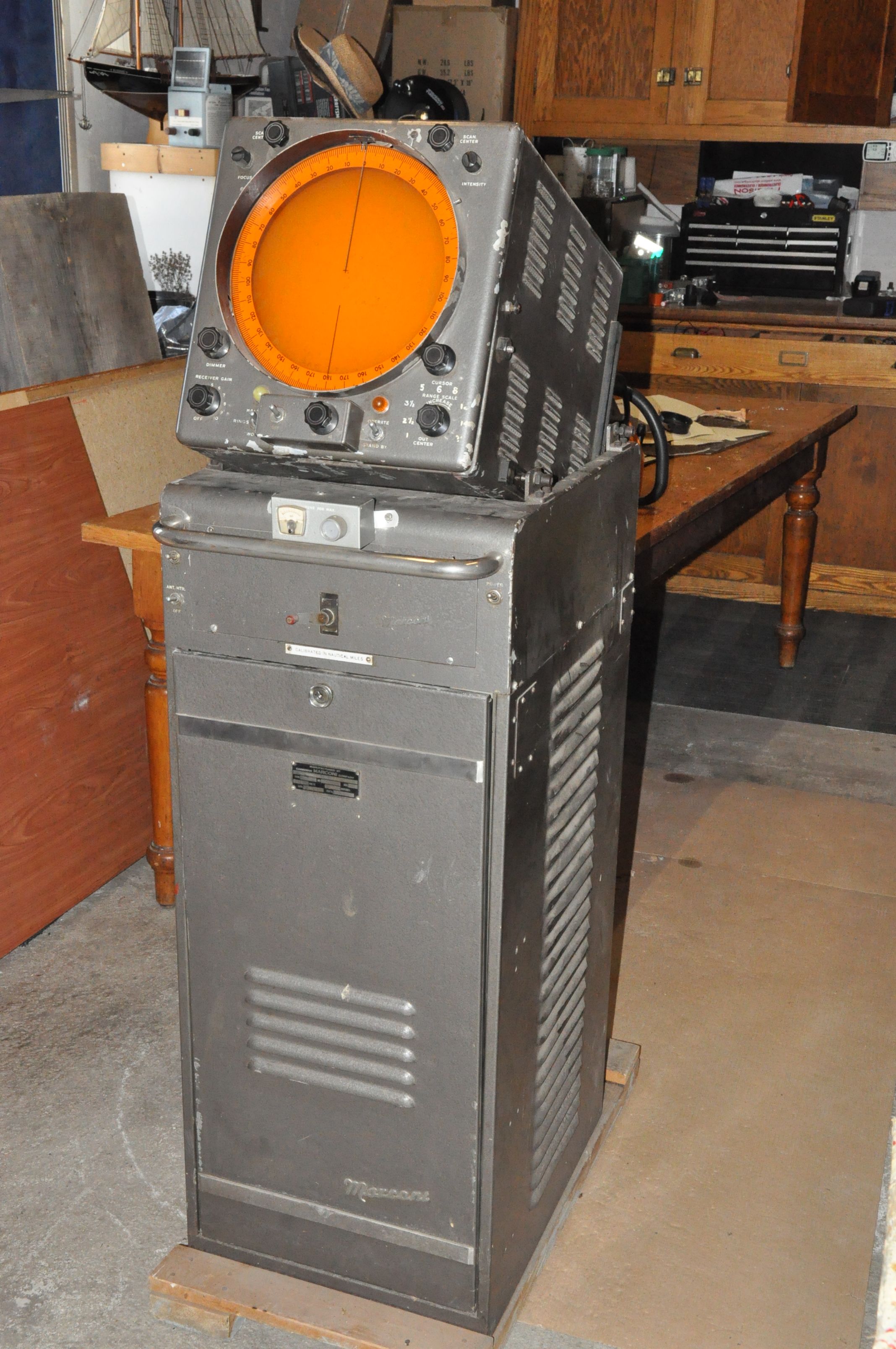
SPERRY MARINE RADAR - MK 2
This was a medium range, surface search radar designated as a High Definition Warning Surface (HDWS) set. From the early 1950's, until well into the 1970's, almost every ship in the RCN was fitted with the Sperry Mk 2. Although its primary use was to locate other ships, helicopters, navigation aids and shorelines, it was very effective in detecting submarine periscopes. This type was fitted aboard HAIDA. After life expiry, the Mk 2 was replaced by the Sperry Mk 127E solid state radar.
Peak power 30 kilowatts Operating frequency 9375 Mcs +\- 45 Mcs Pulse length 0.25 microseconds Pulse repetition rate 1000 pulses per second Scanner rotation 15 rpm Beam Width Horizontal - 2 degrees
Vertical - 17 degreesRange markers Fixed 0.5, 2, and 5 mile intervals +/- 1%
Variable - 0.3 to 20 miles +/- 2%Range scales 1, 2, 6, 15 and 30 miles Resolution Range - 80 yards
Bearing - 2 degreesIndicator CRT size 12 inch diameter Dimensions and Weights Indicator - 27"D x 20"W x 51"H ; 350 lbs
Scanner - 20"L x 50"W x 49.5"H ; 300 lbs
Tx/Rx - 26.5"D x 22"W x 17"H ; 190 lbs
M-G Set - 36"L x 15"W x 12"D ; 330 lbsPower requirements 115 VAC 60 Hz, 1000 watts Contractor Sperry Gyroscope, Great Neck, N.Y Procurement The RCN ordered 12 sets in August 1950 Documentation The oldest version of the Sperry Mk2 Mod 0 / Mod1 Operators manual is dated September 1947. Sperry reference 23-211
ANTENNA TYPES
This is the Sperry Mk2 PPI display as fitted in the Ops Room of HMCS HAIDA. (Photo by Jerry Proc) There were three versions of the HDWS antenna. The first one employed a meshed screen as the parabolic reflector. Next came the slotted metal reflector. Lastly, the Sperry had a solid metal parabola. A screened reflector offers less wind resistance but its not as efficient as a metal one.
 |
| These are two slightly versions of the mesh screen antenna. There are numerous examples of RCN ships bearing this version of the reflector. (Image provided by Darren Scannell) |
 |
| Here is another mesh screen example aboard HMCS Crusader. (Image provided Scannell) |
 |
| This is the Mk2 Mod 0/Mod1 version of the parabolic antenna which appears in the 1947 version of the operators manual. It is not known what type of ship would use the slotted reflector. There is no evidence that it was ever used by the RCN. Click on image to enlarge, (Image provided by Darren Scannell) |
 |
| The Sperry Mk 2 antenna aboard HAIDA is an example of a solid metal parabolic antenna. It origiaally came from HMCS Chaudiere after she paid off. . (Photo by Jerry Sullivan) |
Left side view of the Sperry Mk II transceiver box. (Photo by Jerry Proc) Right side view of the Sperry Mk II transceiver box. (Image courtesy Sperry Marine) Mk II modulator chassis. (Image courtesy Sperry Marine) Here is an extract from the Naval Board minutes from 23 August 1950. Under the Accelerated Defence Programme, they were given money to spend. The Accelerated Defence Program was enacted soon after the outbreak of the Korean War. It is believed that the original plan was to buy only Sperry HDWS set for HMCS Magnificent but they expanded it to include 12 destroyers along with the training schools. The total cost for this procurement was estimated to be $240,000. .
Commander Plomber, the senior RCN officer in Korea, wrote a report on the effectiveness of the HDWS radar in the period from July 1951 to June 1952. Unfortunately there is no way to know if the HDWS set being referred to is the one with the screened or solid metal parabolic antenna . Here are some citations from that report:
ADVANTAGES
1) Under good operating conditions, it was possible to carry out firing on North Korean Junks up to a range of approximately 7,500 yards. Corrections for splashes observed. were applied with a good degree of accuracy after a little practice. Two Junks were destroyed using this method of fire control.
2) Pilotage was was conducted from the Sperry using one fixed point. Ranges and bearings were accurate enough to obviate cross fixing. This is especially valuable in nanrrow waters where currents and tidal streams are strong and where space is at a premium.
3) The set was not difficult to calibrate . Accuracy is constant.
DISADVANTAGES
1) In spite of anti-clutter control, weather had a marked effect on the Sperry's performance. In heavy rain, the set seldom picked up small craft. Fog or a high humidity condition had little effect on operation whereas snow rendered the set about 20% efficient.
2) High winds, over 40 knots demanded that the set be turned off due to the weak construction of the aerial coupling. HMCS Cayuga's Electrical Office investigated the problem and manufactured a sturdier model which served as a temporary fix. Because the Sperry was to be used in A/S warfare on the North Atlantic, priority needed to be given to providing a permanent fix die this problem.
3) After many running hours the efficiency of the set gradually falls off. This was noticed in two ways. a) The gyro follow up failed to keep in step with the ship's lead. b) The PPI display faded from time to time. This fault was sometimes caused by a partial failure in the crystal current control .A jury-rig to manually control the crystal current was made on several occasions when a total loss of the equipment at the tine could not be afforded.
SUMMARY
The Sperry Mk II was likely the improved version of the original HDWS set whose model designation is not known aat this time. Was it Sperry Mk 1? Mk II was the version with the solid metal antenna parabola, the redesigned antenna coupling and the automatic frequency control circuits.
The Mk II predecessor , is erroneously being referred to as an HDWS instead of a model number. HDWS is an acronym! The MK II radar manual we have aboard HMCS HAIDA is titled Sperry MKII Mod0/Mod1 and dated 1948. There were no dates on any of the drawings nor does it describe anything about Mod 0 or 1. Another reference on the cover of the Sperry MkII Mod0 and 1 manual makes reference to C-5923/000/MB000. Manual BRCN213 (June 1961) , was the RCN's Catalog of Materials. In the radar section, it lists Sperry MkII as Mod 2. So that means this radar had three modifications during its life.
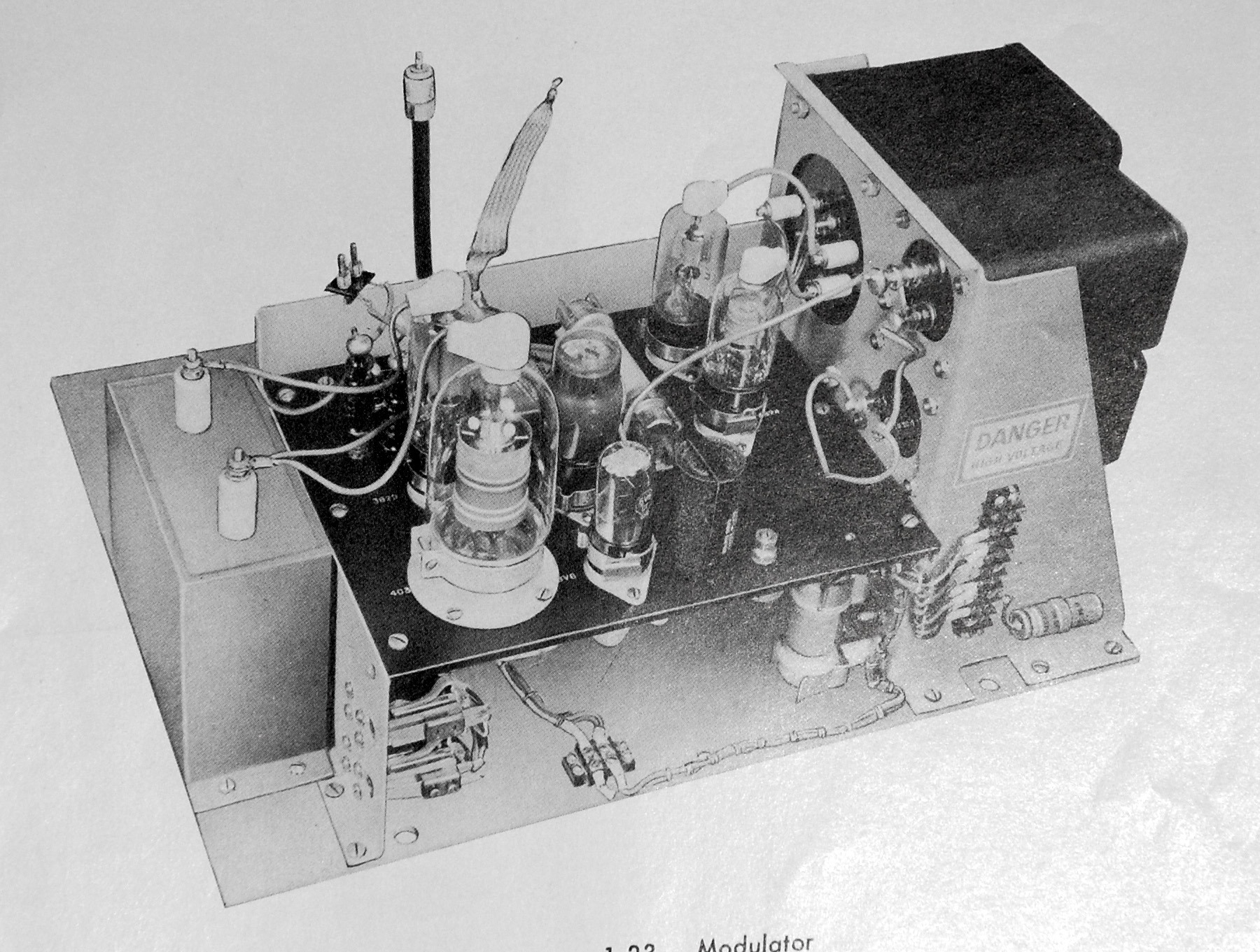
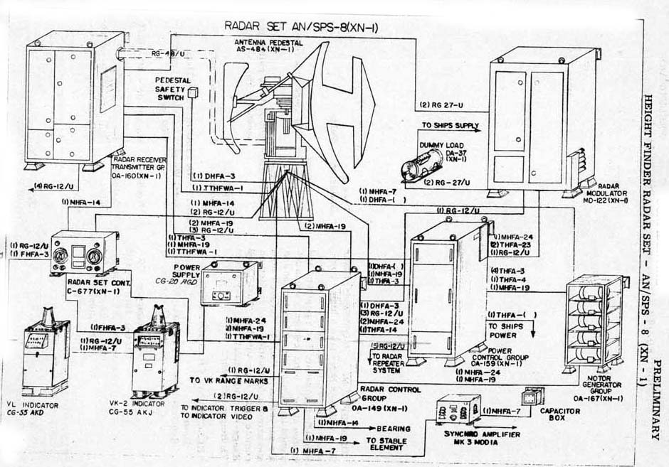
SPS8-8A
AN/SPS8-8A is listed in BRCN 213 (circa 1960) , the RCN's Materials Catalogue. This is an integrated search and height finding radar fitted aboard HMCS Bonaventure and removed during the 1967 refit.
Basic Specs:
Power level for variant SPS8-8A: 1 megawatt.
Frequency: 3430 to 3570 MHz
Range: 72 nautical miles
Pulse repetition rate for 8A variant : 450 and 700 pps.
Power input: 440 volt 3 phase AC; 20 kva
Manufacturer: General Electric.
Click here to see a pictorial of the SPS-8 systemSPERRY 127E
A solid state navigation radar employing integrated circuit (IC) technology and first fitted aboard DDH 280 class. Tribals. It used a 12 inch CRT and was designed on the precepts of the Radio Law, Safety Agreement of Life at Sea (SOLAS), the American FCC standards and the British DTI standards.
SPECIFICATIONS Peak power 25 kilowatts Range 120 miles Operating frequency 9410 Mhz +\- 30 MHz Pulse length 0.05 to 1.2 microseconds depending on range Pulse repetition rate 500 to 4000 pulses per second depending on range Scanner rotation 30 rpm for 1/4 to 6 mile scales
15 rpm for 12 to 120 mile scalesDimensions and
WeightsIndicator - 27"D x 20"W x 51"H ; 350 lbs
Scanner - 20"L x 50"W x 49.5"H ; 300 lbs
Xcvr - 26.5"D x 22"W x 17"H ; 190 lbs
M-G Set - 36"L x 15"W x 12"D ; 330 lbsAntenna 7 foot end fed, slotted array, waveguide type Power requirements 115 VAC 60 Hz, 600 VA Circa 1975- 76 AN/SRR-4
AN/SPS8-8A is listed in BRCN 213 (circa 1960) , the RCN's Materials Catalogue Radio Receiving Set AN/SRR-4 is an improved shipboard receiver tor use with AEW equipment. Two antennas are u.sed on a shipboard installation ln order to provide full 360 degree coverage. Click here to see a system pictorial.
SU
The SU radar was a WWII vintage USN type and was fitted aboard PRESTONIAN class frigates. Known for its good surface clutter rejection, it also had an A-scan for use as a gunnery spotting radar for the 4" gun and the maximum range mark was 80 miles. The radome for the SU is rather plain - roughly 4 feet tall and 2.5 feet in diameter, has a rounded top but just a little flat. Sixteen bolts clamp the radome to the base. Four or five cables and the waveguide come out the bottom, just off-center of the base, in the arc of a circle.
Type: Surface search shipborne radar
Operating frequency: 9085.5 MHz (X band)
Power Output: 50 kw
Pulse Lengths: 1/4 to 1 microsecond pulse
Initial Procurement by USN: Quantity 896
Year of procurement: 1944.
One photo of HMCS Algonquin 224 shows her fitted with the SU radar.An extract from the Naval Board minutes from 23 August 1950. indicates they were given money to spend under the Accelerated Defence Programme. As a result. HMC ships SWANSEA, WINNIPEG, OSHAWA, WALLACEBURG, and ROCKLIFFE were to be fitted with SU radar in lieu of the existing 271 and RXC sets. In the same breath, the radar upgrade to the SU type was to be deferred until such time as a suitable HDWS set could be procured.
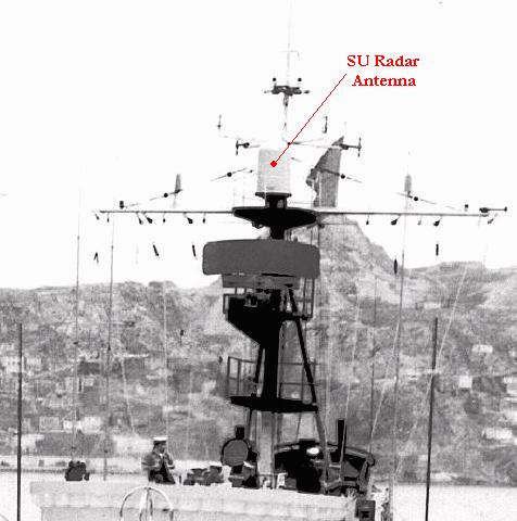 |
| The SU radar is shown fitted on the foremast of a Prestonian class frigate. (Photo courtesy Sandy McClearn) |
AN/UPM-99
This was the IFF test set used to test the Mk X IFF system.The UPM-99 simulated the responses of aircraft transponders, and in doing so, the shipboard technicians could verify the correct operation of the UPA-24/C1008 decoder for each radar display fitted with IFF. The safety of the ship depended on this equipment for if the aircraft in question did not respond with the right set of codes it would be declared as hostile.
The VD-2 radar repeater is listed in BRCN 213 (circa 1960) , the RCN's Materials CataloguePartial specs:
CRT size - 7 inches
Ranges: 4, 20, 80, and 200 miles
Power: 120 volts 60 Hz 188 watts
 |
| VD-2 graphic courtesy USN |
VK-2 and VK-3 Radar Repeaters
The VK-2 and VK-3 radar repeaters are listed in BRCN 213 (circa 1960) , the RCN's Materials CatalogueV-K, VK-2, VK-3 VK-3a,VK-4, VK-4a, and VK-5 function as standard PPI repeaters, off-centered PPI repeaters, or as expanded off-centered PPI repeaters. They may also serve as plotting centers. These equipment types can display target data obtained from an AEW system, information from a dead reckoning analyzer, or target data from a shipboard radar. Service as a radar relay or target designation transmitter, relaying target bearing and range to remote stations, can also be performed. The VK series equipments are similar, differing slightly in electrical performance.
Range Scales: VK, VK-2, VK-3 - 4, 10, 20, 40, 80, and 200 mi in centered and off-centered operation VK-3a,VK-4 - 4, 10, 20,40, 80, 150, 200 and 300 mi in centered and off-centered operation . VK-4a, VK-5 - Fixed, 4, 20, and 150 mi in centered and off-centered operation; vari-able, 4 to 300 mi in centered and off-centered operation
Range Accuracy: VK - 0 to 18,000 yd, +100 yd; 18,000 to 100,000 yd, +1% of actual range; 0 to 200 mi, +5%of actual range
VK-2,VK-3 - 300 to 10,000 yd; i100 yd; 50 to 200 mi, i0.4 mi
Bearing Indication: True and relative
Bearing Accuracy: Within 2.2 deg at all speeds
Pulse Repetition Frequency:
VK - 57 to 2,000 pps
VK-2, VK-3, VK-3a, VK-4, VK-5 57 to 3,000 ppsManufacturers:
VK, VK-3, -3a - General Electric Company
VK-2 - Hazeltine Electronics Corporation
VK-4, -4a, -5 - Westinghouse Electronic Corp
This radar repeater was installed in HMCS HAIDA's Operations Room. It had a 10 inch CRT and its primary feature was the ability to offset the sweep from the centre of the screen. The VK5 contained 101 vacuum tubes. Westinghouse Electric of Baltimore built 400 of these for the USN. The RCN obtained theirs from Canadian Westinghouse in Hamilton , however the production quantity is unknown.
| IP226 Repeater Specs
H- 42.125 in
|
PP734 Power Supply
Weight 145 lbs
|
 |
| VK5 aboard HMCS HAIDA - top view |
 |
| VK-5 front view with lower maintenance cover removed. |
 |
| Front view with upper maintenance panel swung down. |
 |
| With 101 vacuum tubes, the VK-5 is quite complex inside. This chart illustrates the key signals found in the circuit. |
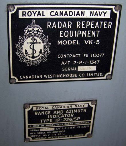 |
| VK-5 (IP-226/SP) repeater nameplate |
| All photos in this table by Jerry Proc |
 |
| VK-5 (PP-734A) power supply |
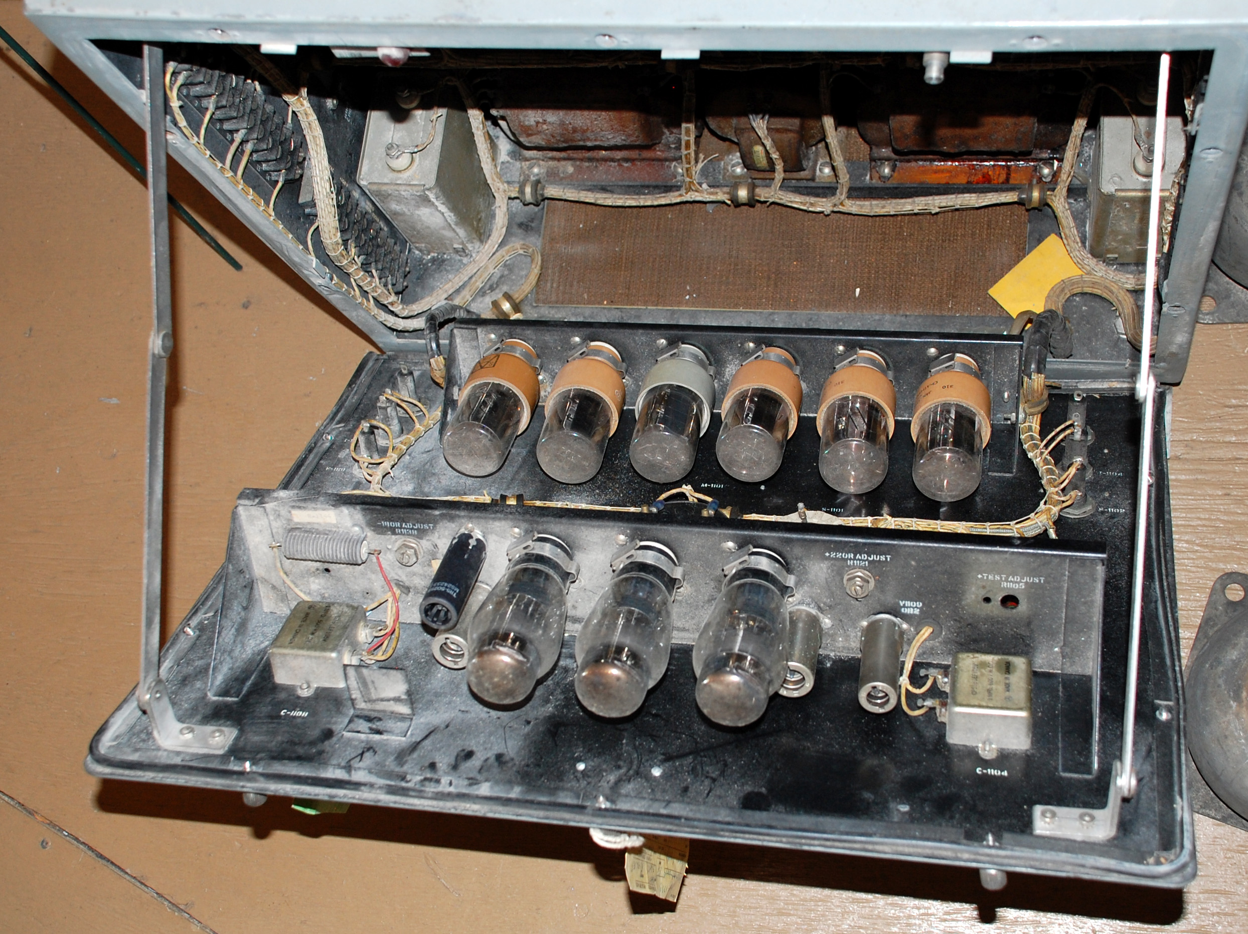 |
| The front panel of the power supply is swung down to show how the tubes are arranged. |
 |
| Looking at the rear of the power supply enclosure from the front. |
 |
| VK5 power supply nameplate |
| All photos in this table by Jerry Proc |
VL-1 Radar Repeater
The VL:-1 radar repeater is listed in BRCN 213 (circa 1960) , the RCN's Materials Catalogue Repeater Equipment VL and VL-1 are compact, self-contained units designed for permanent shipboard installation at a point remote from the radar height-finding units.VL and , VL-1 repeaters were made by the General Electric Company, They employ a 12 inch CRT within ranges of 20, 40, 70, and 140 miles but contain provisions to change the ranges to 20, 40,100, and 200 miles, if desired. Selection of a presentation width may be made at the unit or at the remote radar control system. These repeaters are often used in conjunction with VK series repeater equipments which repeat search information.
Specifications:
Pulse Repetition Frequency: 60 to 3, 000 pps
Range Selection: Normal - 20, 40, 70, and 140 mi
Alternate - 20, 40, 100, and 200 mi
Sweep Range - 270 mi max undistorted
Range Accuracy: 1% of total scale
Range Markers: 5, 10, 20, and 50 mi
Sector Width: 10, 30, or 360 deg
Operating Voltages and Power Requirements:115v 10%, 60 2 cps, 1-ph, 1, 510 va,
 |
| VL-1 image courtesy Tpub.com |
ADVANCEMENTS IN RADAR
Modern radar also provides excellent moving target indication by use of the 'Doppler shift' effect that a radio wave undergoes when it's reflected from a moving target. If the target is moving towards the radar, the frequency of the echo will be shifted upwards and vice versa. Traditionally, target detection is hindered by "clutter" echoes arising from echoes reflected from the ground, sea water or raindrops. Modern radar, with its higher transmitter power, higher frequency and more sensitive receiver, causes clutter to be even more pronounced so that even flocks of birds may show up on the screen. Antenna design can reduce these effects, and the use of circularly polarized waves reduces rain echoes. Coupled with a computer, the radar can be programmed only to display targets that are moving above a certain velocity. The wartime radar operator had to manually interpret the mass of data displayed on his PPI. In the world of air traffic control, as an example, the tracing of multiple targets would be impossible without the assistance of electronic processing. Progress toward satisfying this need had to await the arrival of large-scale integrated circuits, charge-coupled devices and the development of the technology for processing digital signals. Another important advance has been the computerized handling of video data, as in automatic plot extraction and track formation.Radar engineers recognize that detection of a target still remains a matter of statistical probability, rather than certainty, in spite of all the great advances in components made since World War II.
Contributors and Credits:
1) Sandy McClearn <smcclearn(at)ns.sympatico.ca>
2) Øyvind Garvik <oygarvik(at)online.no>
3) SU radar console http://www.ibiblio.org/hyperwar/USN/ref/RADONEA/img/COMINCH-P-08-03-54.jpg
4) Robert Langille, <ewcs(at)ewcs.ca>
5) Le Musée Québecois de la Radio - Jacques Hamel, VE2DJQ
6) Gilbert Audette <gilberta(at)xplornet.ca>
7) AN/SPN-8 https://maritime.org/doc/ecat/cat-0244.htm
8) VK2 and VK3 http://radar.tpub.com/TM-11-487C-1/TM-11-487C-11437.htm
9) VK sseries. http://radar.tpub.com/TM-11-487C-1/TM-11-487C-11439.htm
10) VD-2 https://maritime.org/doc/ecat/cat-1239.htm
11) VL-1 radar repeater http://radar.tpub.com/TM-11-487C-1/TM-11-487C-11440.htm
12) MX-1618 http://radar.tpub.com/TM-11-487C-1/TM-11-487C-11385.htm
13) AN/SPS8-8A http://www.hazegray.org/navhist/canada/systems/radar/
14) AN/SPS8-8A http://radar.tpub.com/TM-11-487C-1/TM-11-487C-11222.htm
15) AN/SRR-4 https://maritime.org/doc/ecat/cat-0374.htm
16) SPA-8 https://maritime.org/doc/ecat/cat-0222.htm
17) Darren Scannell [hawkone(at)hawk-graphics.com]
July 26/24

