THE RADIO DITTINGS ON A FEW AIRCRAFT
ALBATROSS CSR110
 |
| CSR-110 was the Canadian designation for the Grumman HU16
aircraft. (DND photo) |
The CSR-110 was the Canadian Forces designation for a small number
of Grumman HU-16B Albatross amphibious aircraft that were acquired second-hand
from the U.S. in the 1960s. CSR stood for Canadian Search and Rescue (the
Canadian military used the “CSR” prefix for some SAR aircraft types). The
110 was simply the type number in the RCAF’s post-war numbering system.
The acquired aircraft were HU-16B variants, originally built for
the U.S. military, but used in Canada strictly for search and rescue operations.
They were operated by the Royal Canadian Air Force (and later unified Canadian
Forces) primarily in Pacific and Arctic coastal SAR roles during the mid-to-late
1960s. Only a few were used, and they were replaced by de Havilland
Canada DHC-5 Buffalo and later CC-115 Buffalo aircraft.
Here’s the CSR-110 fleet list with serials and service notes:
RCAF / Canadian Forces CSR-110 (Grumman HU-16B Albatross)
9301 – ex-USAF HU-16B (serial 51-7223), entered RCAF service 1960,
based at Comox, BC, for SAR.
9302 – ex-USAF HU-16B (serial 51-7267), in service 1960, also at
Comox.
9303 – ex-USAF HU-16B (serial 51-7166), in service 1960, SAR duties
in BC coastal waters.
9304 – ex-USAF HU-16B (serial 51-7246), in service 1960.
All of the 93xx aircraft were obtained from the U.S. under mutual
assistance programs. These remained operational until around 1966–1968,
when they were retired. The electronics fit for the Canadian Albatross
aircraft is not known at this time.
Noah Stegman Rechtin has compiled a listing
of electronic fits that could be found in the Albatross variants operated
by the US Navy, the USAF and the US Coast Guard. In addition he provides
this file which shows the different designators for all
American Albatross variants..
AVRO ANSON
 |
| ATR-11 radio installation aboard an Avro
Anson aircraft. This radio was built by RCA in Montreal. (Photo
reference RE2151-16) |
B-26 MARAUDER
 |
| This the radio operator's station in a B-26 Marauder bomber. This
particular exhibit, as seen in the National Air and Space Museum in Washington
DC, has been re-created in a fuselage section of an aircraft called "Flack
Bait" (Photo by Jerry Proc) |
Flak Bait served with the 449th Bombardment Squadron, 322nd
Bombardment Group, Eighth and Ninth Air Forces. It flew from bases in England
and, after D-Day (on which it flew two missions), from bases in France
and Belgium. In 21 months, Flak Bait acquired more than 1,000 holes, had
its hydraulic system shot out twice and its electrical system once, returned
twice on one engine, and came back once with an engine on fire. By war's
end, it had flown 202 bombing missions, more than any other American bomber
over Europe. (Photo by Jerry Proc).
CANSO ( PBY) FLYING BOAT RCAF
 |
| Canadian Forces photo |
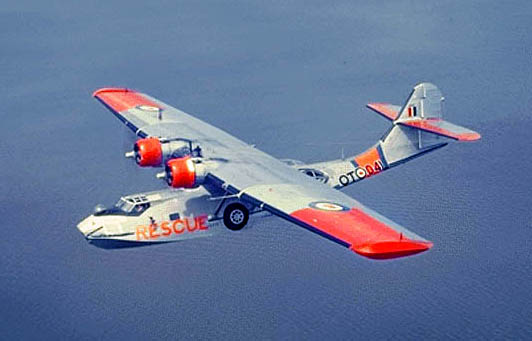
Canso is the Canadian designator for the flying boat while
Catalina is the US designator.
HF Radio: 2 x AT-6 receivers ; 2 x AT-7 transmitters. 1.5
to 20 MHz (plus 375 and 500 KHz) for the transmitter and 140 to 400 KHz
plus 480 KHz to 21 MHz for the receiver.
Search Radar: ASV
Other: SCR-578 (Gibson Girl emergency radio)
Navigation: MN-31A ADF
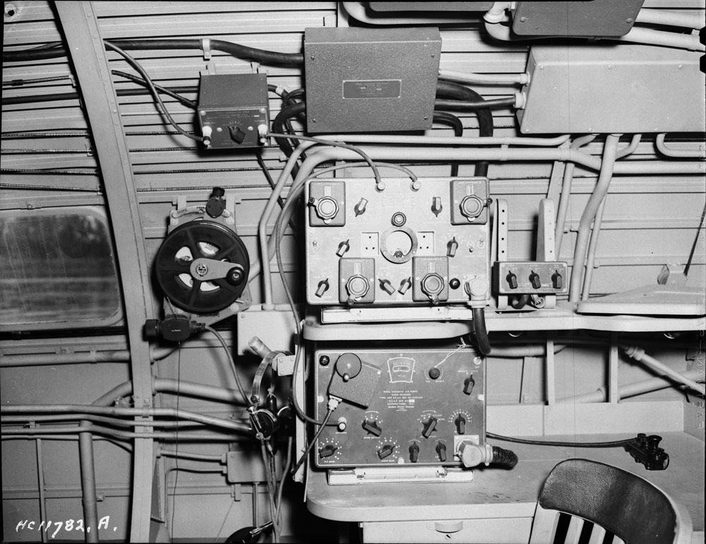 |
| Canso radio oops position circa 1941
(Photo
#HC11782.A) |
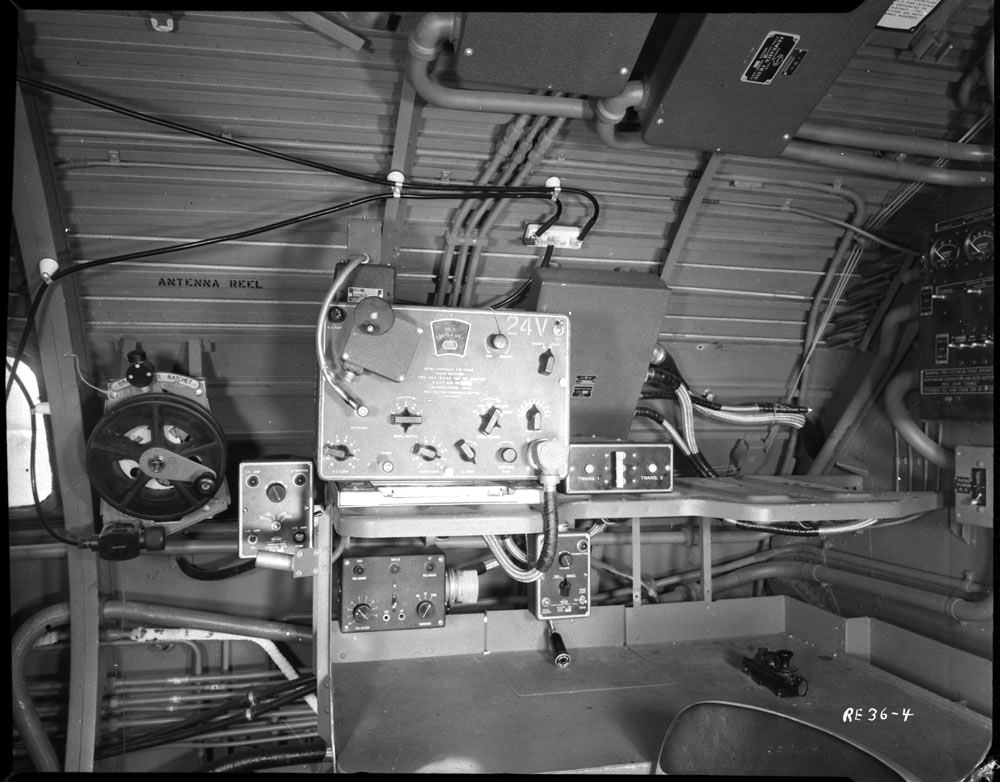 |
| Canso radio operators position in 1943.
The
receiver in the photo is the AR-6, built by Canadian Marconi, RCA and Northern
Electric. Directly below the receiver is a control box for the Bendix
TA-2 transmitter.Some RCAF Canso/Catalina aircraft carried the AT-12 transmitter,
possibly three of them in a single rack, instead of the TA-2. (Photo
RE36-4) |
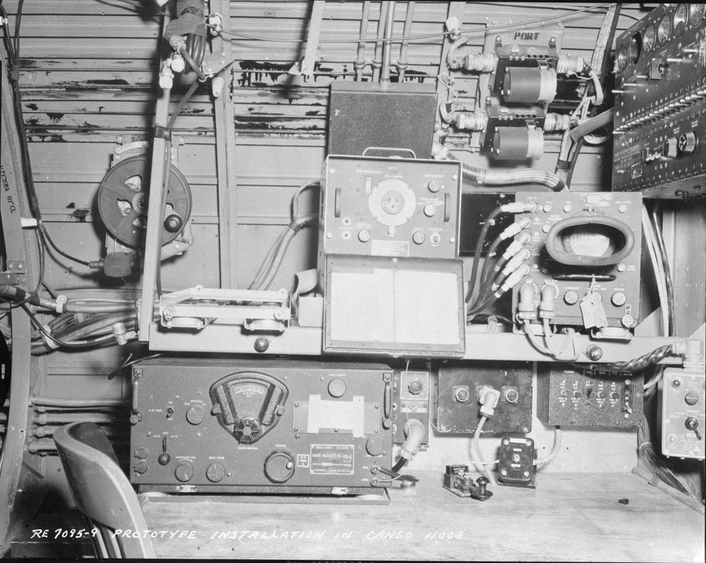 |
| Canso protoype installation photo for the radio operator was taken
April 14, 1943. In front-center is a BC221 frequency meter with a BC-348
receiver below it and to the left. (Photo #7095) |
.jpg) |
| Canso transmitter, circa 1953. The empty space
on the right bottom side of the rack strongly suggests that a second TA-2
transmitter could be mounted in this rack. (Photo RE36-6) |
CC-129 DAKOTA (DC-3/C-47) RCAF 1959
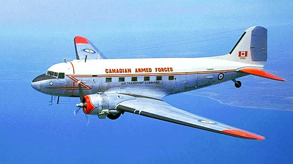 |
| Canadian Forces photo |
REGULAR VERSION
Vintage: 1959
HF radio: SCR-287 consisting of BC-348 and BC-395. ARC-8 consisting
of BC-348 and ART-13
VHF radio: SCR522, AT/ICA67, ARC-502
Radar: AN/ANP-1 (SCR-718)
IFF: AN/APX-6
Navigation
Radio Compass (ADF): AN/ARN-6
Marker Beacon: MN53B
Omni Direction Finding: SARAH. (AN/ARR-8 airborne search receiver
for SAR, 70-300 MHz)
Loran 'A' : AN/APN-4
ILS: AN/ARN5-A
AS A NAVIGATIONAL TRAINER
Vintage: 1959 estimated.
HF Radio: ARC-8 consisting of BC-348 and ART-13
VHF radio: Dual ICA67 or ARC-502
UHF radio: ARC-552
IFF: AN/APX-6
Radio Altimeter: SCR718
Navigation
Radio Compass (ADF) : AN/ARN-6
Marker Beacon: Bendix MN53B
ILS: AN/ARN-5 or Bendix VOR/ILS
Other: BC-453B LF range receiver.
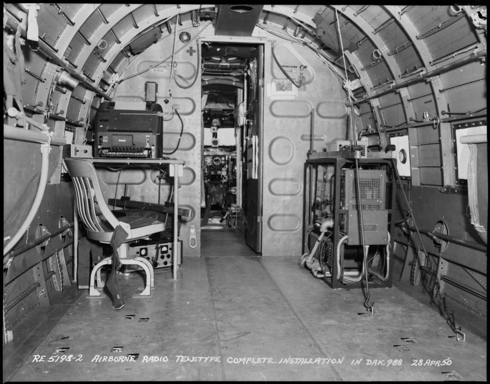 |
| April 28, 1950 - An airborne radioteletype bay aboard
Dakota #988. This aircraft was was part of a communications
squadron which could conceivably lead to the aircraft being used as a platform
to test out airborne RTTY. The date accompanying the photo would of course
indicate it was based in Sea Islamd BC at the time. At the left side top,
is a Model 15 teletype machine with an FSC107 frequency shift converter
below it. The receiver for this is likely in the rack on the right
side. There is also a Bendix AT-12 transmitter in the right hand rack,
It is the item nearest the camera The radio operator’s compartment
is immediately in front of the bulkhead on the port side, Download
image to enlarge. (NAC photo RE5198)
S/ 988 History:
Delivered to USAAF 25Apr 1945. Transferred to RCAF as
S/N 988 on 01 May 1945.
Transferred to 168 HT (Heavy Transport ) Sqn RCAF May1945.
Transferred to 121 KU Squadron, RCAF Sea Island, April 1946
Reserialled as 12961 Jun70.and subsequently owned by four
different commercial entities. |
 |
| Radio panel in CC129 Dakota. Click on image
to enlarge. Of note, is the 20 channel selector switch at the bottom centre
of the image. It attached to the VHF command radio which was the
AF/ICA-67 (Via Dakota manual) |
CH-113 LABRADOR HELICOPTER
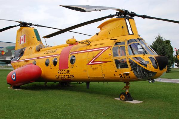 |
| September 2008: This CH-113 is part of the collection of the Canadian
Air Force Museum, Trenton Ontario. (Photo by Jerry Proc) |
The avionics configuration (circa 1996-97) for the CH-113/CH-113A
helicopter fleet is as follows:
Communications Installation:
-- AN/ARC-505 HF/SSB radio
-- AN/ARC-513 VHF/FM transceiver
-- AN/ARC-511 VHF/AM radio
-- AN/ARC-164 UHF/AM radio
Intercom Installation:
-- A81-2 intercom
Emergency Beacon Installation:
-- AN/URT-505 ELT (emergency locator transmitter)
-- AN/URT-506 CPI (crash position indicator)
-- DK-100 UAB (underwater acoustic beacon)
Special Installation:
-- AN/UIH-503 loudhailer
Navigation Installation:
-- AN/APN-509 radar altimeter
-- AN/ARN-89A ADF (Automatic Direction Finder)
-- AN/ARN-504 TACAN (Tactical Air navigation)
-- AN/ARN-509 Omega (System now defunct)
-- AN/ARN-126 VOR/ILS (VHF omnidirectional ranging)
-- AN/APS-505 weather radar
-- AN/ARN-515 Loran C Long-range navigation.
-- BR15-DF-88 VHF/VHF-FM/UHF direction finder (DF)
Compass Navigation Installation:
-- J4 compass
Radar Identification Installation:
-- AN/APX-77 IFF (identity, friend or foe)
Provided by Jeff Rankin-Lowe
DIRIGIBLES
 |
This is the radio room of the Graf Zeppelin.
Click to enlarge. (Photo credit unknown at this time) |
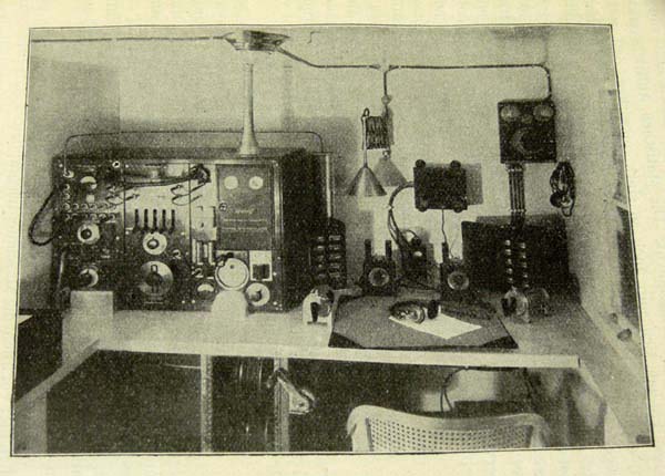 |
| Wireless office of the German dirigible LZ126. From the book " Z.R.
III - LZ 126 to America". The LZ126 was built in Friedrichshafen in 1924
for the U.S. Navy as part of reparations for WWI and was subsequently renamed
the ZR-3 "Los Angeles". It was flown across the Atlantic from Germany to
Lakehurst, New Jersey in October 1924. |
LANCASTRIAN
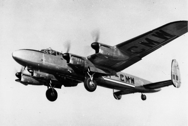 |
| The Lancastrian was a Lancaster bomber converted for civil use.
It's main job was to carry passengers trans-Atlantic and was the
first Canadian aircraft to carry a flying radio officer. The a/c in the
photo is Lancastrian CF-CMW of Trans Canada Airlines as seen in
August, 1946. The major external modifications were the extended
nose section and the closing up of the bombay. (Public Archives
Canada PA-61649 via Spud Roscoe) |
 |
| William Lucas is operating the radio equipment aboard a Trans Canada
Airlines Lancastrian aircraft in September, 1945. (Air Canada
photo X20365. Submitted by Spud Roscoe VE1BC) |
LOCKHEED HUDSON
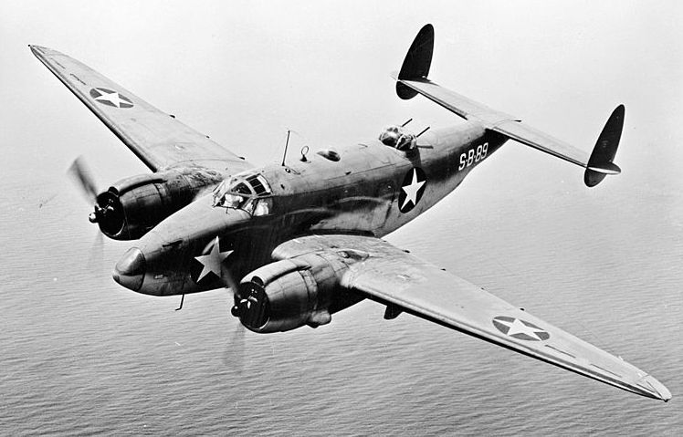 |
| Lockheed Hudson. It was developed from
the Lockheed Super Electra airliner. ( Library of Congress photo) |
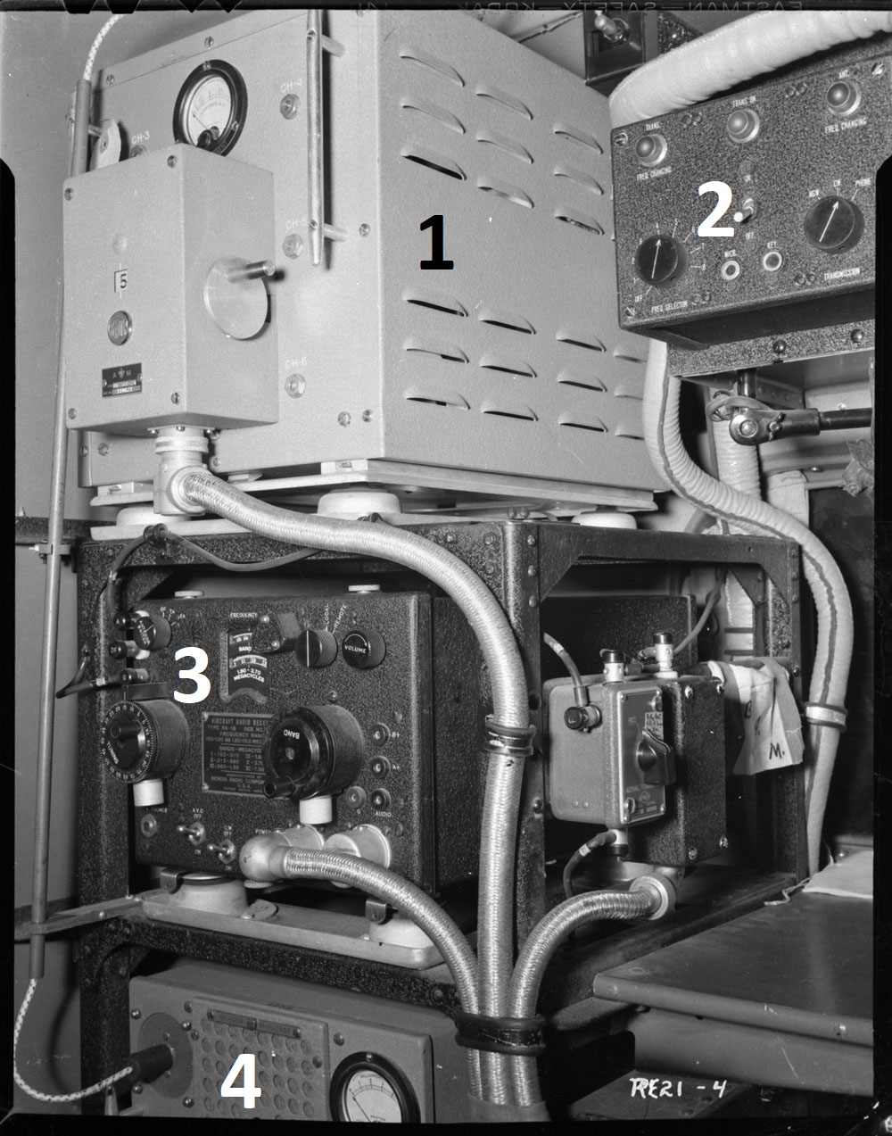 |
| Radio operator's station in the Lockheed Hudson.
Download image to enlarge. The table surface is at the right. (NAC
photo)
Item #1 - Bendix MT-36 antenna tuning unit for the TA-2 transmitter.
Item #2 - Bendix MT-34 remote control for the TA-2 transmitter.
Item #3 - Bendix RA-1 receiver
Irem #4 - Bendix TA-2 transmitter.
Frequency range: 2.9 - 17.0 MHz ; 300 - 600 KHz when used with the
MT-36
Power: 100 watts
Modes: CW and AM
Frequency control: 8 crystal control and autotuned channels. |
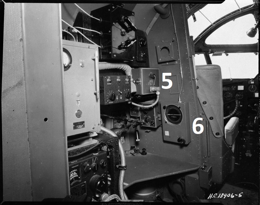 |
| Directly behind the pilot is the Radio operator's table in the Hudson.
Download image to enlarge. Note the position of the flameproof key
on the table surface. (NAC photo)
Item 5 might be the Interphone Amplifier.
Item #6 is the azimuth indicator for the Direction Finder |
B-24 LIBERATOR ( RCAF)
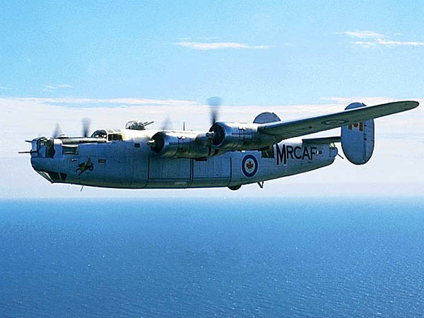 |
| During WWII, the RCAF flew 1,200 B-24Js. (Canadian
Forces photo) |
LIBERATOR
HF radio: Command SCR-274N. Liason SCR-287 consisting of BC-348
Rx and BC-375 Tx
VHF Radio for Command: SCR-522
Search Radar: ASV10 (10 cm)
IFF: SCR-695
Radio Altimeter: AN/APN-1
Navigation
Radio Compass (ADF): SCR-269G
LORAN: AN/APN-4
Autopilot: C1(M-H) or A5
Other
REBECCA AN/APN-2 (SCR-729)
Sonobuoy System AN/CRT-1 sonobuoys with AN/ARR-3 sonobuoy receiver
LIBERATOR (BR)
HF radio: Command SCR-274N. Liason SCR-287 consisting of a BC-348
Rx and BC-375 Tx
VHF radio: Command SCR-522
Emergency radio: SCR-578 (Gibson Girl)
Interphone: BC-347
Search Radar: SCR-517 (ASG) 10 cm
IFF: SCR-595
Radio Altimeter: AN/APN-1
Navigation
Radio Compass (ADF) SCR-269G
Marker Beacon Receiver: RC-43
Direction Finding: AN/APN-2 ( SCR-729)
LORAN: AN/APN-4 ( possibly AN/APN-9 in later versions of the aircraft)
Other
AN/CRT-1 Sonobuoys
AN/ARR-3 Sonobuoy receiver
MISCELLANEOUS PHOTOS
.jpg) |
| Loop antenna production line at Northern
Electric, 1941. (NAC photo) |
.jpg) |
| (L-R) Lockheed Hudson, Cansso, Fairey
Battle (hidden) and Avro Anson aircraft on June 30, 1943. (NAC photo) |
SHORT SUNDERLAND
 |
| The 4 vertical antennas near the tail are part of the ASV Mark II
a 176 MHz, 7 kw radar system. It is one of the treasures brought
to the United States by the Tizard mission in 1940 and subsequently manufactured
by Philco as well as REL in Canada. (Photo provided by Dave Whiting,
VA3QG) |
 |
| This is the radio ops position in the Sunderland aircraft. At the
left is the R1155 receiver. At the right is the T1154 transmitter..
(Photo provided by Dave Whiting, VA3QG) |
Contributors and Credits
1) Spud Roscoe <spudroscoe(at)eastlink.ca>
2) Jeff Rankin-Lowe <siriusproductions(at)sympatico.ca>
3) Andre Guibert <aguibert(at)sympatico.ca>
4) Tom Brent navyradiocom@gmail.com
5) DC3 S/N 988 history http://www.joebaugher.com/usaf_serials/1944_5.html
\6) Albatross info https://caspir.warplane.com/aircraft/serial-search/aircraft-no/200000451
Back To Home Page
Aug 21/25


.jpg)


.jpg)
.jpg)

