S.S. JOHN BROWN RADIO ROOM

Liberty ship was the name given to the EC2-S-C1 type ship designed for "Emergency" construction by the United States Maritime Commission in World War II. Liberty ships were nicknamed "ugly ducklings" by President Franklin Delano Roosevelt.

The first of the 2,751 Liberty ships was the SS Patrick Henry, launched on Sept. 27, 1941, and built to a standardized, mass produced design. The 250,000 parts were pre-fabricated throughout the United States in 250 ton sections and welded together in about 70 days. One Liberty ship, the SS Robert E. Peary was built in four and a half days. Each ship cost just under $2,000,000 to build.

The Liberty was 441 feet long with a beam of 57 feet. Her three cylinder,  triple expansion marine steam engine was fed by two oil burning boilers. The engine produced 2,500 hp thus propelling the ship at 11 knots. Five holds could carry over 9,000 tons of cargo, plus airplanes, tanks, and locomotives could be lashed to the  deck.  These ships carried a merchant crew of about 44 and 12 to 25 Naval Armed Guard. The Brown is only one of two operational Liberty ships left.
 

During WWII,  when a convoy was ready to sail , the Radio Officers on Liberty ships  were required to attend  a " convoy conference ".with the Master of their ship.  Ian Malcom , the third Radio Operator of a Liberty ship , provides  the "The instructions to Radio Operators" in his book  "Life Aboard a Wartime Liberty Ship".

Office Of The Navy
Port Director
17 Battery Place
New York, N. Y.

Instructions To Radio Operators

1. If ashore and you cannot locate your ship, please phone:
COMMUNICATIONS DUTY OFFICER - Bowling Green 9-6220 — Extension 42.
DO NOT MENTION THE NAME OF YOUR SHIP — Talk slowly
and distinctly giving your own name only. Officer on duty will be
able to inform you how to make ship. Be patient — it will take a few
minutes. Always use a PHONE IN A BOOTH - Try to have a pencil
ready — Use the back of this notice to write on.

2. The Master of your vessel will receive your communication plan.
When he comes aboard, BE SURE TO ASK HIM FOR IT. YOU ARE
TO HAVE THE COMMUNICATION PLAN IN RADIO SHACK
THROUGHOUT THE VOYAGE. IT IS TO BE GIVEN TO MASTER
UPON REACHING DESTINATION.

3. You will have Master instruct all Watch Standers to keep you
informed immediately when:
(a) you are in fog or cannot see Visual Signals from Commodore.
(b) When emergency exists, as in the presence of the enemy.

4. You will obtain from the Master - WIMS III — and retain possession
in shack while at sea. [See note 1]

5. Obtain from the Master the latest BAMS (Broadcast to Allied Merchant Ships)
Lettered and Numbered messages of interest to you. They are marked
“TO BE GIVEN TO RADIO OPERATOR” and the Master receives them from the New
York Port Director.

6. The Radio Officer shall survey each private broadcast receiver aboard
his vessel. Any receiver not listed as approved in WIMS II
Appendix “D” is to be made inoperative by removing vital parts.
This order applies to receivers owned by ALL SHIPS OFFICERS
as well as CREW. You are responsible to Naval Authorities for the
execution of this order, the Master will support you in this.

7. Keeping Radio Log — Conform with instructions in WIMS II — Art.45

8. General regulations for testing in U.S. inland waters *was given your
Master upon arrival in New York. Obtain these regulations from him.
Testing of transmitters between conference time and ships departure
is PROHIBITED unless permission is granted by Port Director as
shown below:
Freq. _________ kcs — Time _____________ EWT – Approved ___________

9. BE ALERT - SAVE YOUR LIFE AND THE LIVES OF YOUR
SHIPMATES - DON'T TALK - DON'T TALK - THE ENEMY IS LISTENING

[Ed Note 1] WIMS/-I, II, III,    Wartime Instructions for Masters of Merchant Vessels.
A set of standing orders to ships masters traveling in convoy.

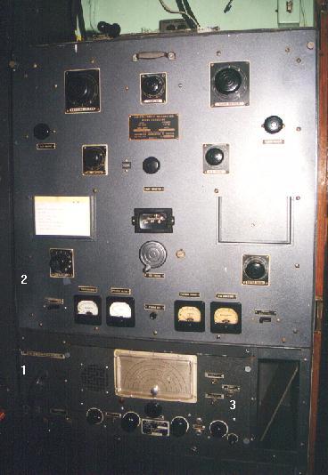
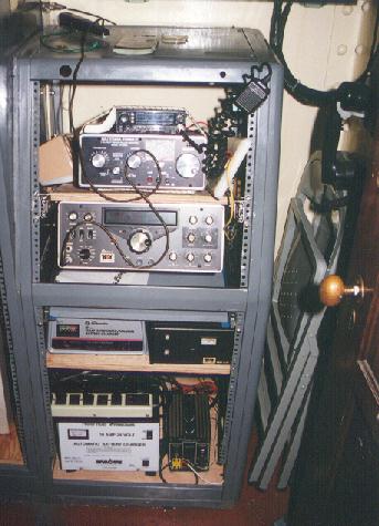
Presented here is the radio room of the S.S. John Brown.  The room  is located on the port side behind the bridge. The free floor space in the room is about 6 feet by 8 feet.

KHJL

 
jbrr1.jpg
All equipment in the radio room was supplied by Radio Marine Corporation of America, the marine division of RCA . This photo shows the Model 3U Radio Unit standing against the forward bulkhead. It was fitted with a work surface. (Photo by Jerry Proc)

1) Type 'C' Crystal Radio. Range: 350-515 kHz. It used a cat's whisker. (Closeup)
2) Model 8601 auto alarm receiver. Built August 1942.
3) Auto alarm master switch.
4) AR 8510 receiver. Range: 16-650 kHz. Built September 1944.
5) ET 8024A CW transmitter. Ranges 350-500 KHz. 200 watts, xtal controlled.
6) Battery charger.
7) ET 8025 low power, emergency transmitter. 350-500 kHz; 40 watts. Powered
    from a 12 volt source; crystal controlled. Built August 1942.
8) Antenna transfer switch.

Each transmitter was equipped with RM28 keys.


jbrr2.jpg
Standing against the starboard bulkhead of the radio room and at right angles to the 3U console, was the other radio unit. (Photo by Jerry Proc)

1) Motor generator transfer switch.
2) ET 8023-D1 high frequency CW transmitter. VFO controlled. Power output is 200 watts between 2 and 24 MHz. Built November 1944.
3) AR 8506-B receiver. Coverage is 85-550 kHz and 1.9 to 25 MHz. Built in  September 1944.

3U/4U DIFFERENCES

Saul B. Yochelson of the Lane Victory radio department explains the differences between the 3U and 4U radio units.

"Originally, Liberty ships only had  medium frequency (MF) radio equipment. MF was considered as 500 KHz and down. The integrated modular unit was designated as an RMCA-3U or an equivalent made by Mackay Radio. The 3U had three frames: the left one contained the Auto Alarm, the center unit housed the MF AR-8510 receiver and the main ET-8024A MF transmitter. The right frame contained the AR-8025 emergency MF transmitter along with various switches for controlling the battery chargers.

Later, perhaps in 1944 or 1945 (I first saw such an installation in mid-1945), HF rigs were added to Liberty ships. These were implemented by a fourth frame that was installed at right angles to the 4U, between the Radio Room door on the starboard side of the Radio Room and the 3U. The added frame contained an HF receiver (the 8506), the 8023 HF transmitter, and a transfer switch that was used to switch the motor generator (in the base of the 3U) between the MF and HF main transmitters. Technically, this added HF frame was not part of the RMCA-3U.

In contrast to the Liberty ships, Victory ships were always outfitted with integrated MF and HF equipment. Essentially, a fourth frame was added between the Auto Alarm frame and the MF frame and the integrated modular system was designated as an RMCA-4U. Again, Mackay made a similar unit. If one  looks closely, the left frames of the 3U and 4U are the same, the second frame of the 4U is the same as the "outboard" Liberty Ship HF frame and the two rightmost frames of the 4U are the same as the two rightmost 3U frames. Thus, the 4U had the same components as the augmented 3U but arranged in one, flat, row.

Interestingly, the HF transmitter on the John Brown uses a VCO while the similar HF transmitter on the Lane Victory is crystal controlled. I sort of remember hearing that most of the 4U HF transmitters were converted to crystal control after the war".


ANTENNAS

Liberty ships had two main antennas. Regardless of wartime or commercial operation,
when the booms were operating it was necessary to disconnect one end of each antenna, lower it and coil up the wire. Before getting underway, the antenna wires had to be restored back to normal. In many ports ships were not allowed to use their radio while in some ports, the radio room would literally be sealed.

The new result was the Radio Officer had nothing to do while a ship was in port so he was usually the first one down the gangplank and the last to return. Made a lot
of other shipmates jealous.

AMATEUR RADIO
bhamradio.jpg
In order preserve the historic appearance of the Brown's radio room, the ship's amateur radio station has been set up in this modest position in a small room adjacent and aft of the radio room. This is how it looked on August 6, 2000. (Photo by Jerry Proc)
Feb 29/20
Back To Home Page