BRITISH ELECTRONICS FIT
The aim of this web document is to compare the wartime electronics
fit between the British and Canadian built Lancaster bombers.
As often with combat mission equipment, the answers can depend
on the specific application or duties of the unit or squadron, and in this
case the exact radio fit could depend on the county of manufacture of the
aircraft (UK or Canada) Also the requirements of the individual squadron
and the duties of the individual aircraft need to be taken into account.
Modifications and changes would also take place during the service life
of the aircraft as required.
Later in World War II, some bombers carrying out special duties
began to carry additional specialized equipment for navigational and similar
purposes. The equipment was more complex than that normally carried and
a specially trained "Set Operator" was carried to operate it and interpret
the results. His equipment was usually referred to as "the gubbins" and
he was regarded as a specially intelligent person, a "Gen kiddie".
COMMUNICATIONS
AIRBORNE CIGAR (ABC)
This was only fitted to the Lancasters of 101 Squadron. It used three
aerials; two were sticking out of the top of the fuselage and
one under the bomb aimer's position. These aircraft carried a German speaking
crew member on board and were used to jam radio frequencies being used
by German night fighters and feed false information on allied bomber
positions to them. Due to the nature of the equipment, the enemy was able
to track the aircraft and as a result 101 Squadron suffered the highest
casualty rate of any bomber squadron. First fitted from about mid-1943,
ABC remained until the end of the war.
BOOZER
A radar detector system of lights mounted on the aircraft's instrument
panel. It lit up when the aircraft was being tracked by the low-UHF band
Würzburg-Riese ground radar and early model Liechtenstein B/C and
C-1 airborne radar. In practice it was found to be more disconcerting than
useful, as the lights were often triggered by false alerts in the radar-signal-infested
skies
over Germany.
IFF
This was a Mkk II IFF , system designator ARI 5000. Te version fitted
would also depend on the date in question as the design and installation
of the various marks of IFF evolved.
Transponder R3002 (12V), R3082 (Tropical 12V), R3003 (24V), R3083
(tropical 24V)
Control unit type 17, 18
Aerial type 90, 93
OBOE
A very accurate navigation system consisting of a receiver/transponder
for two radar stations transmitting from widely separated locations in
Southern England which, when used together, determined the aircraft's position.
The system could only handle one aircraft at a time, and was fitted to
a Pathfinder aircraft, usually a fast and manoeuvrable Mosquito which marked
the target for the main force rather than a Lancaster.
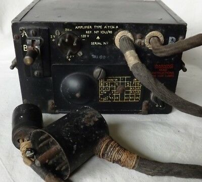
TINSEL
The code name 'Tinsel' referred to a type of equipment carried by
RAF bombers which was used for jamming Luftwaffe night-fighter controller's
speech frequencie It consisted of an audio microphone mounted inside one
of the bomber's engine nacelles, the output of which fed into the aircraft's
standard T1154 radio transmitter. The wireless operator could listen in
to the frequencies used by the defending forces and then, when he heard
a German transmission, tune his transmitter to the Luftwaffe frequency
and transmit the amplified engine noise on the same frequency, thus jamming
the enemy transmission.
Although not very effective as a jammer, the noise produced merely
acted as background noise to the transmitted speech, Tinsel did have the
effect of making the night-fighter crew's job of distinguishing the instructions
received from the ground more difficult.
VILLAGE INN. A radar-aimed gun turret fitted to some
Lancasters in 1944.
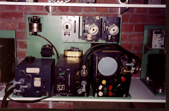
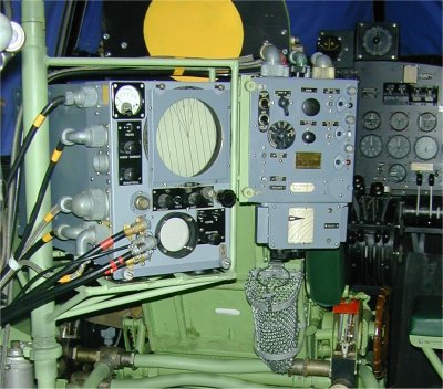
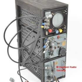
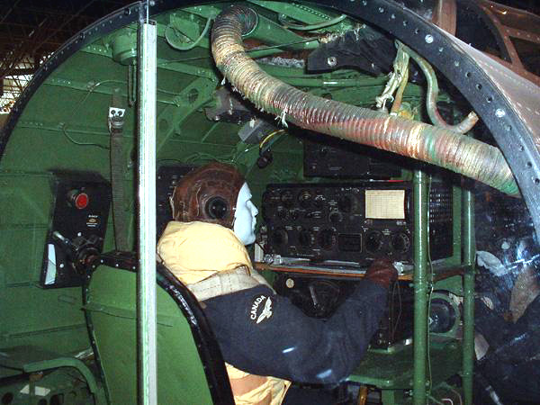
COMMUNICATIONS
The radio operator's position in the aircraft is at the aft end of
the navigator's table facing forward. Most of the radio equipment is mounted
in front of the radio operator on or below the navigator's table as shown
in figures lA and 1B below. The radio operators station can in several
different configurations as depicted in the photos below. Facing
the radio operator are two Bendix TA.12C Transmitters mounted one above
the other at the right side of the table. (See Fig t 1A) Mounted
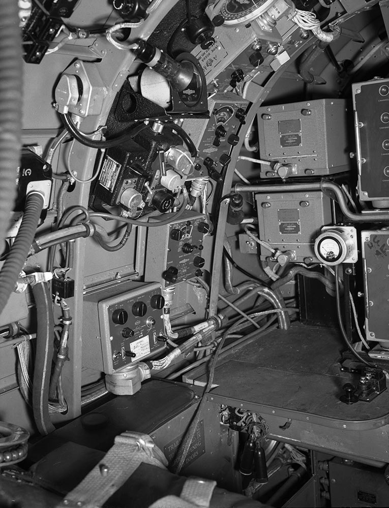
at the left of these transmitters are two Bendix MT.5 3 loading units for
the transmitters, and above them are the 39260 Antenna Relay and
a type 3939 Antenna Switch for selecting either the fixed or trailing aerial
and for grounding the fixed aerial when not in use.
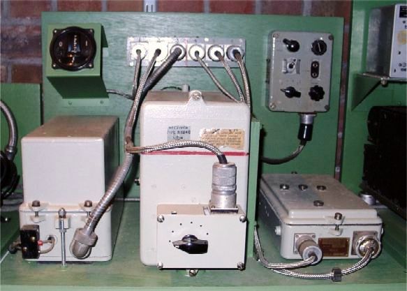
Mounted behind the transmitters is the main junction box 1 containing
circuit breakers for the four main units. Also mounted at the left of the
radio operator on the navigator's table are the MR.9B Remote Control for
the RA.I0B Receiver, and the 3616B Remote Control for the TA.12C Transmitters.
Above the radio operator's head, on the port side of the fuselage is mounted
a panel carrying the BC.461 Remote Control unit for the trailing aerial
motor, the remote control for the compass receiver, the MR.1 SA remote
control and the MN.22A Azimuth Indicator for the D.F. loop, the IN.4A Left
- Right Indicator, the radio operator's MI.22A Intercommunication station
box and the R.3090 equipment remote control panel. Below the navigator's
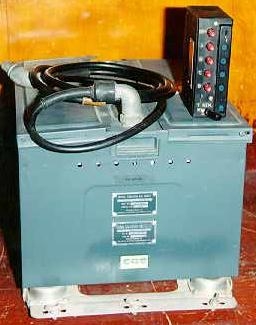
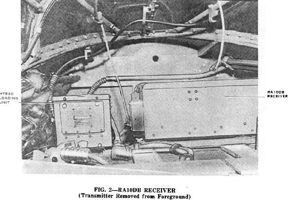
table (see Fig. 1 B) are mounted the Bendix MP.28BA Power Unit containing
the high tension dynamotor and modulator for the transmitters, junction
boxes 2 and 3, the Bendix MN.26C Compass Receiver and the Bendix RA.I0DB
General Purpose Receiver. The TR.l196 Transmitter Receiver is located
above the front spar on the port side of the fuselage and the ARI. 5122
system is mounted just aft of the entrance door on the starboard
side of the aircraft.
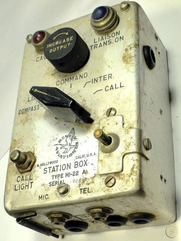
INTERCOMMUNICATION
Complete intercommunication for the crew was provided by the use
of a Bendix MI.22A station box at each crew position . All staion boxes
were connected to an interphone amplifier. The crew would plug in their
headphones and mics into the station box. MI.22 provided the ability to
listen or talk on liaison or command transmitters and receivers, and to
listen to the compass receiver. By means of a switch normally locked
in an inoperative position it was also possible to put either the liaison
or command transmitter on the air. Station boxes are provided at the following
positions:-
Bomb Aimer - Port side of the fuselage in nose.
Front Gunner - In front gun turret.
Pilot - On pilot's auxiliary panel at port side of pilot.
Flight Engineer- Below the starboard cockpit rail, just aft
of main instrument panel.
Navigator - At steel tube supporting navigator's table on
left side of navigator.
Radio Operator - Mounted to panel on port side of fuselage
above the operator's head.
Rest Station - On the port side of the fuselage at former 10.
Mid-Lower Gun Turret - On the port side of the fuselage at
former 26.
Mid-Upper Gun Turret - In turret.
First Aid Station - Mounted on starboard side of fuselage
just aft of former 35.
The interphone amplifier is shown as RCAF part number 110U/36 on
the navigators station drawing and that's where the unit was mounted. The
real part designator is 3611B from the Block Schematic drawing. It is a
two-stage, high gain amplifier which provides inter phone facilities for
all crew members. It also supports the use of carbon or dynamic microphones.
Output power is 3 watts. Looking for a photo of the 3611B.
DEFENCE and COUNTERMEASURES
* MONICA Mk 1 (1943). The ARI 5122 system used an R3136 receiver,
a T3135 transmitter and a type 116 indicator.
* IFF Mk II - Reference is made on the 1943 Figure 1 Outline
drawing to R3090/ABK. A Google search on ABK reveals that this is an IFF
Mk II system Another co-ordinate on the drawing is labelled R3003
aerial. Unable to find any detailed info on the R3003 or R3090 devices.
The IFF MK II system was designed to allow switching between any
one of 6 different coded responses, usually specified for various types
of mission. However, in practice it proved difficult to distinguish one
echo from another so generally only position 1 (or A) was used, whilst
the longest, widest response position was used universally as a distress
signal.
In order to respond to the growing number of raiders in service the
aircraft or ship often had to carry multiple IFF units. . The military
services recognized that with the proliferation of radar and other equipment
there was a need for a distinct frequency band for IFF with a common equipment
specification. MK II IFF operated in the 157 to 187 MHz band.
* OTHER EQUIPMENT
It is not known at this time if Canadian built Lamcs were fitted
with any British systems once they arrived in the UK. Other extracts
from AP 2062(F) include the following:
* Power Supply (1943)
The direct current power supply for the radio equipment is drawn
from the main electrical panel supplied by the batteries . (See Fig 1 drawing
) One service from the panel supplies the Bendix and TR.1196 equipment,
another supplies the trailing aerial reel motor and a third supplies the
detonator system from the navigator's panel, the IFF system, the AR1.5083
(GEE MkII), the ARI. 5122 (Monica) systems and the alternator fields.
Mounted on each of the outboard engines are alternating current generators
connected to a junction bracket on the port side of the fuselage forward
of the navigator'S panel. By means of switches on the navigator's panel,
alternating current may be fed to either or both ARI.5083 and ARI.5122
systems.
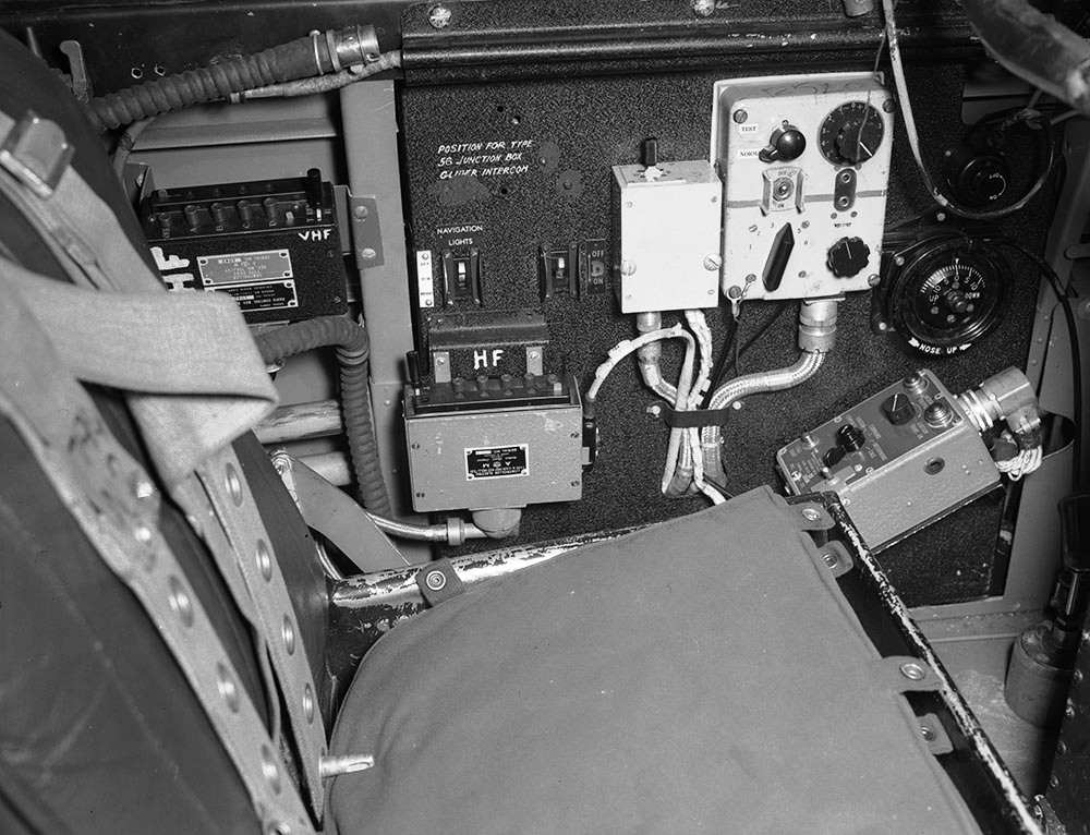
* Pilot's Equipment (1943)
The pilot's auxiliary panel mounted below the cockpit rail on the
port side of the cockpit just aft of the main instrument panel carries
the remote controls for the pilot's radio equipment. The remote
control for the TR.1196 , the remote control for the Blind Approach system
, the pilot's station box and the IFF unit control switch are mounted on
this panel. The panel also contains leads for connecting a glider intercommunication
circuit if required. The Blind Approach mixer switch enables the pilot
to receive Blind Approach signals only, or intercommunication, liaison
and command signals paired with Blind Approach by means of the MN.22A unit.
* Aerials (1943)
Twelve aerial systems are provided for the radio equipment (see Fig.
1). A trailing aerial remote controlled motor driven reel is fitted at
the radio operator's station on the port side of the aircraft. A general
purpose fixed aerial is fitted on the starboard side of the aircraft running
from the pilot's canopy to the top of the starboard fin. A corresponding
aerial is fitted on the port side of the aircraft except that this aerial
is divided into two sections, the front section serving as a sense antenna
for the D.F. Compass receiver and the rear section serving as an aerial
for the TR.1196 unit. Mounted to the top of the fuselage inside the rear
canopy is a remote controlled loop antenna for the D.F. Compass.
Aft of the canopy and mounted to the top of the fuselage is a whip
aerial serving the ARI.5083 unit (GEE) . At former 18 just forward
of the mid-upper turret is mounted another whip aerial serving as the beam
receiving aerial for the Blind Approach units. Two aerials leading from
just aft of the mid-upper turret to the outboard ends of the port and starboard's
tail planes serve the R.3003 unit. Mounted to the starboard underside of
the fuselage opposite of the main entrance door is the dipole aerial for
the Blind Approach and on the port side of the aircraft under the main
entrance door the R.3090 whip aerial is mounted. Projecting from the aft
end of the aircraft is the aerial for the ARI. 5122 unit.
* Detonator Circuit (1943)
The detonator circuit is connected to the ARI.5083 Indicator Unit
and the R.3090-R.3003 Receiver Unit. This circuit it can be operated by
push buttons on the navigator's panel, on the table at the radio operator's
station, and on the right-hand side of the pilot's instrument panel. A
crash switch mounted on the starboard side of former 4 in the fuselage
nose, also controls the detonator circuits provided the isolating switch
on the navigator's panel is turned to LIVE.
IN SUMMARY:
The Canadian-built Lancasters had a different radio fit than the
aircraft built in England. The basic setup was:
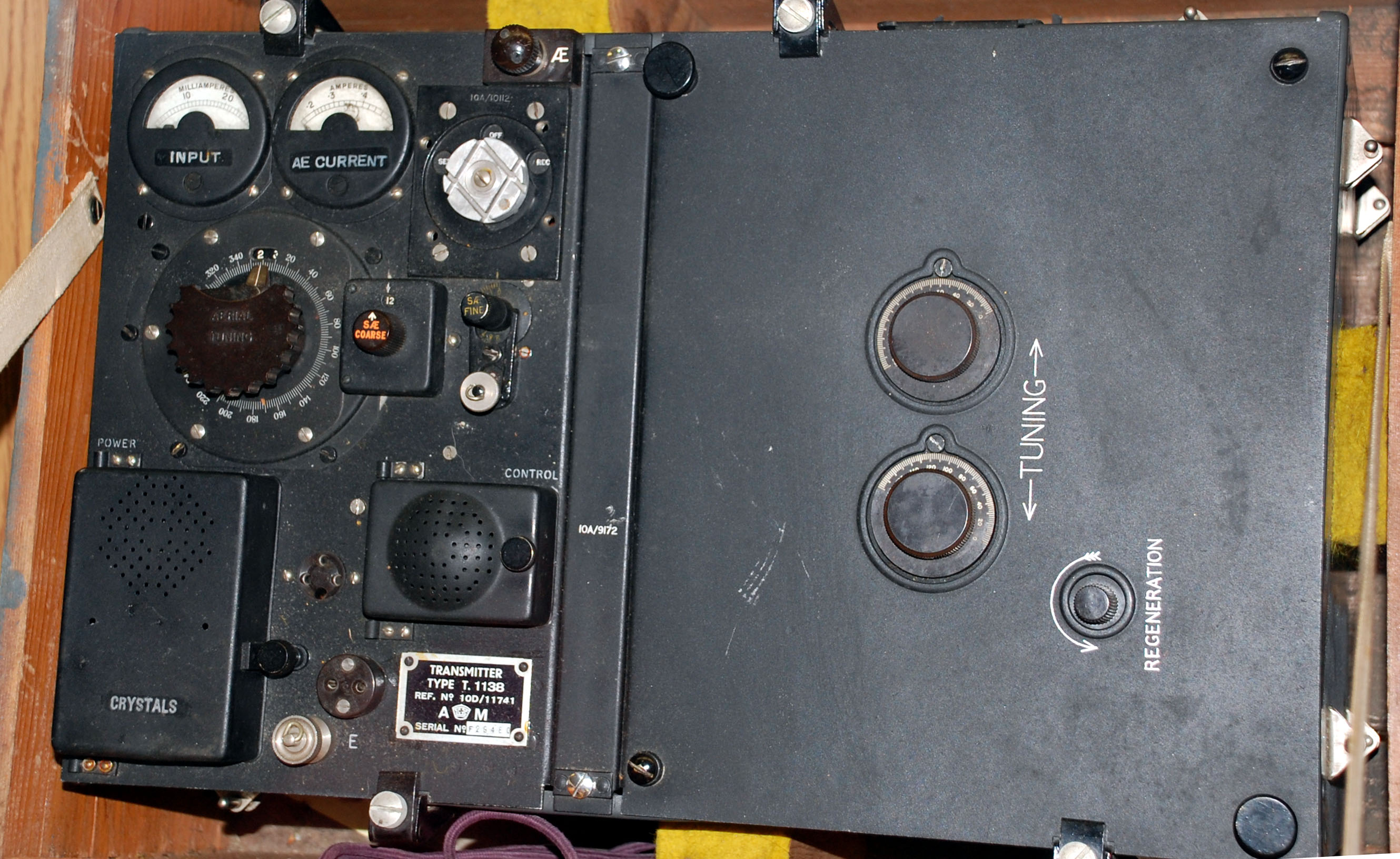
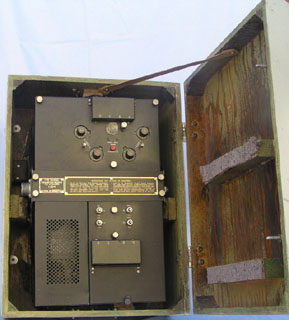
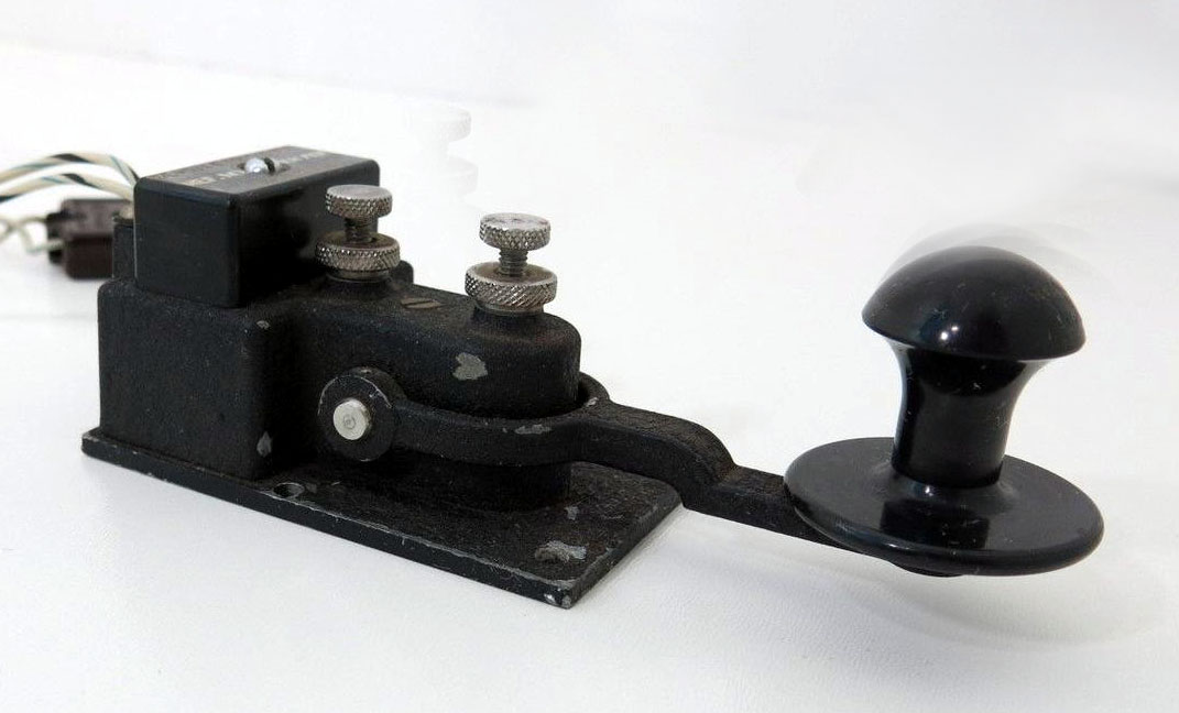
British - One R1155 receiver and one T1154 transmitter were installed
at the radio operator's position.
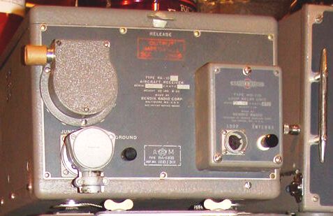
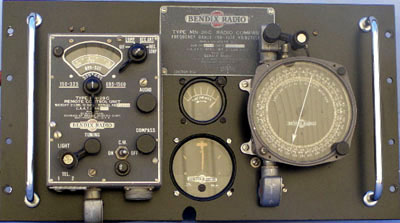
Canadian - two Bendix TA-12 transmitters, one Bendix RA-12 receiver
and one Bendix MN-26 radio compass receiver at the radio ops position.
Rumour has it that when Canadian Lancasters reached England, all
the Bendix equipment was removed and replaced with the R1155/T1154 configuration.


