 |
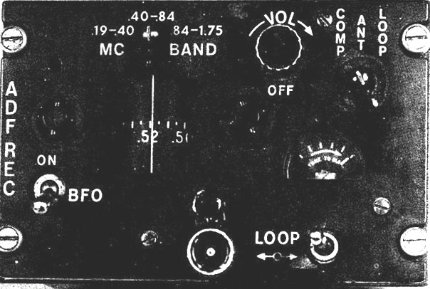
| C-2275 control panel. (Image courtesy Canadian Navy) |
GENERALThe LF automatic direction finder AN/ARN59, is an airborne radio compass system designed to automatically provide a visual indication from which direction an incoming radio frequency signal is received. It also provides for the aural reception of AM signals in the 190-1750 KHz range in three bands: 190-400 KHz, 400-840 KHz, and 840-1750 KHz
The equipment includes the following components:
Receiver (R-836/ ARN-59)
Loop antenna (AT-382/ARN)
Sense antenna
Control panel (C-2275/ARN),
Dynamotor: DY-107/ ARN-59 Dynamotor 24 VDC Input to 110 & 125 VDC, 13 V 100 Hz for loop
3" Compass Heading Indicator: ID-637/ ARN-59
PP-4328/ ARN-59 PS, Power SupplyCONTROLS
The Automatic Direction Finder set is controlled from a control panel (see below) marked ADF REC and located on the Radio and Navigation Control Panel. Controls include a band switch, a volume control, a function switch marked COMP/ANT/LOOP, a tuning control, and a beat frequency oscillator switch.
1. Volume Control. The volume control turns the set on or off, adjusts receiver audio level when the function switch is in COMP, and adjusts receiver RF sensitivity when the function switch is in ANT or LOOP positions.
2. COMP, ANT, LOOP. With the function switch in COMP, the set operates as an Automatic Direction Finder using both the sense and loop antennas. The tuning control may be adjusted to give maximum indication on the tuning meter for any given station with the relative bearing automatically indicated by the No. 1 pointer, radio magnetic indicator. Relative bearing will also be displayed on pointer No. 1 of the pilots, co-pilots, or TACCO's BDHI ( Bearing , Distance Header Indicator. providing the LF TAC push-button on the applicable BDHI control panel is depressed. With the function switch in ANT, the set operates as a communications receiver using the
sense antenna only. With the function switch in the LOOP position, the set operates as a receiver using the loop antenna. The LOOP switch positions the loop antenna when the function switch is in the LOOP position.3. Beat Frequency Oscillator. The Beat Frequency Oscillator (BFO) is used as an aid in the determination of aural nulls on either unmodulated or voice modulated signals. When the BFO switch is ON, place the function switch in the LOOP position and press the LOOP switch in the desired direction to determine the aural null when the tone drops to minimum. Read the relative bearing of the transmitting station from the No. 1 needle on the radio indicator.
4 Tuning Crank. The Tuning Crank tunes the receiver to the desired frequency within the selected band.
NOTE: On the Sea King, with the sonar dome in the water and the ARN-59 in COMP mode, the No.1 needle will indicate a bearing approximately 180 degrees from the correct bearing.
|
| C-2275 control panel. (Image courtesy Canadian Navy) |
Back To Sea King Equipment List
Credits and References:1) Ian Snow RCAF/CF retired.<va3qt-4(at)sympatico.ca> . Training Manual AN/ARN-59 excerpt.
2) http://www.prc68.com/I/ARN89.shtml
May 22/10