 |
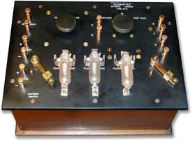 |
| Colour view of the Type 71 |
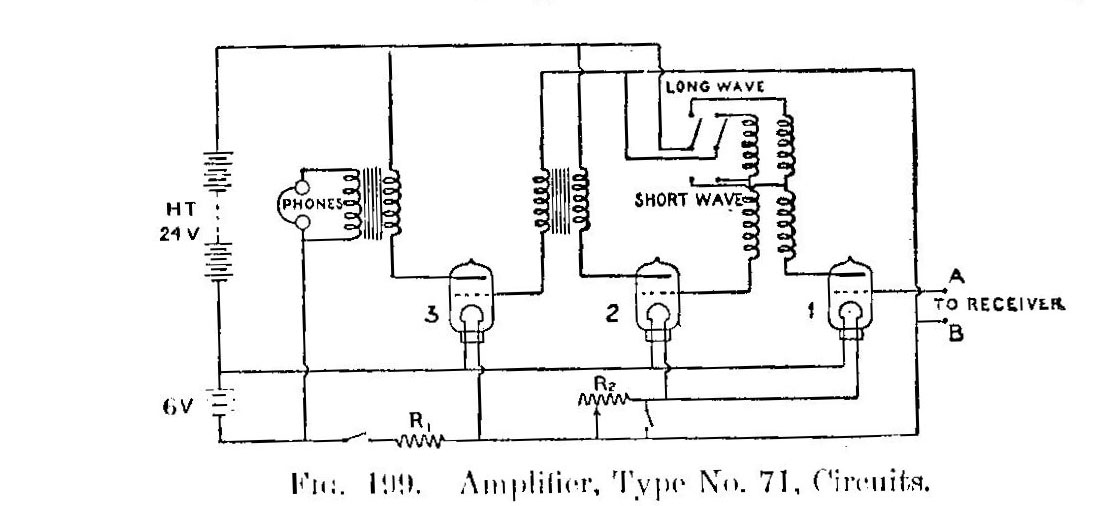 |
| Type 71 schematic , |
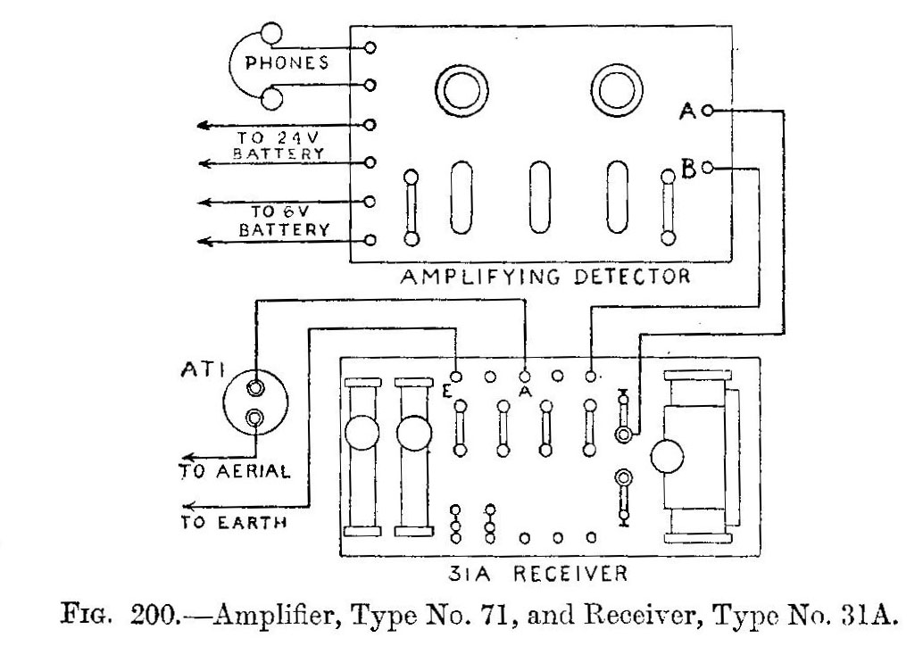 |
| Interconnection from 71 tuner/amplifier to type 31A receiver. |
| Unless otherwise noted all images in this table are courtesy Handbook of Technical Instruction for Wireless Telegraphists). |
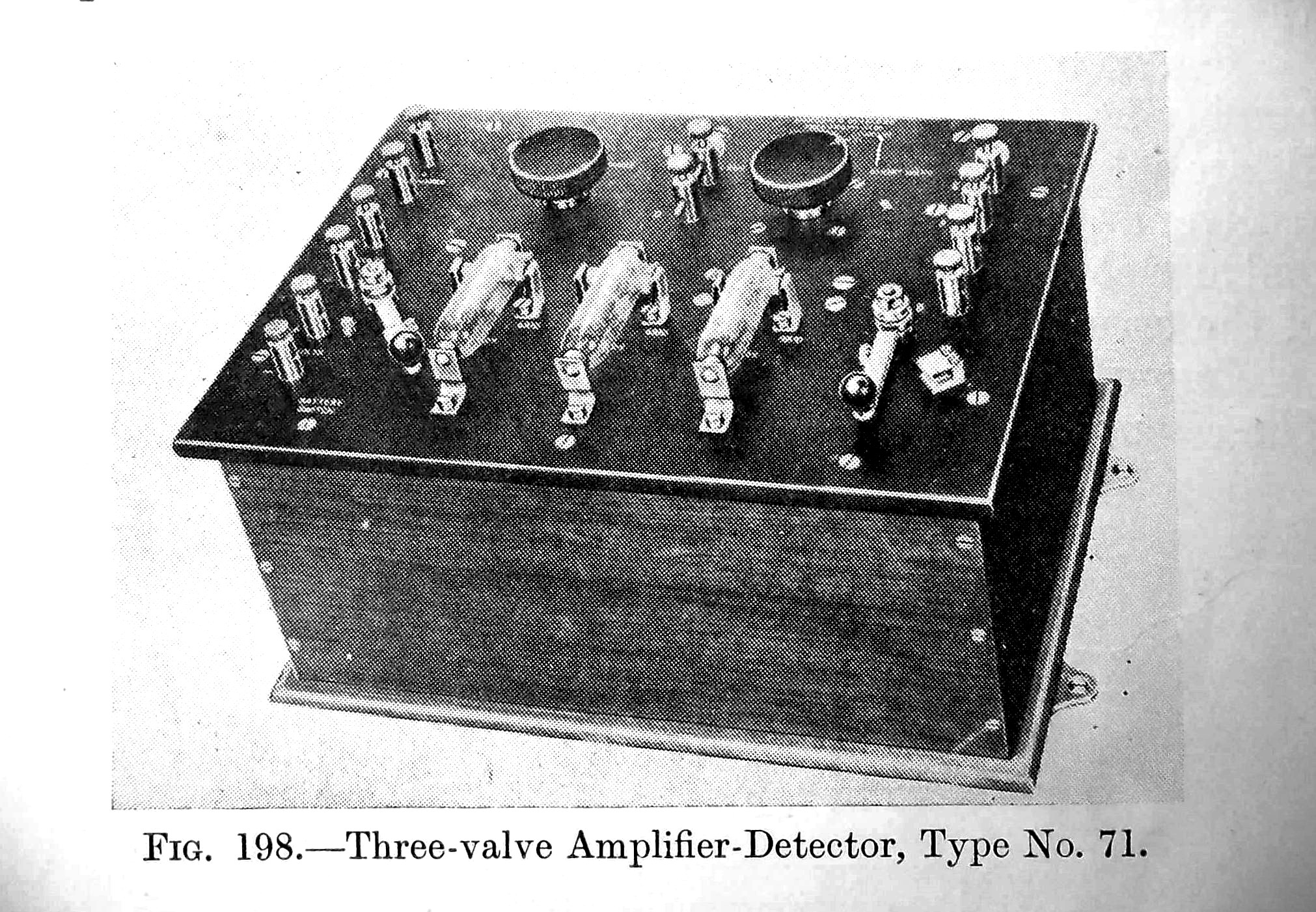
Frequency range: 600 metres or 2,500 metres (Short wave/long wave)
Made by : Marconi UKThis instrument was developed for use aboard ship in connection with any existing crystal receiver or valve tuner used to receive spark signals. For C.W. it requires to be used with an independent oscillator such as Type 73.
The diagram of the circuit is shown in Fig. 199 and the method of connecting it up to a Type 31A receiver. It employs three V24 valves which obtain their filament current from a 6-volt 40 amp/hour battery, and their plate voltage from the ship's 24 volt, 80 amp/ hour emergency battery.
The first valve amplifies the HF. oscillations and transfers them through an air core transformer suitable for the wavelength of the grid circuit of the second valve, where the signals are rectified, and are then transferred through an iron core transformer the grid of a third valve which amplifies the signal.
|
|
| Colour view of the Type 71 |
|
| Type 71 schematic , |
|
| Interconnection from 71 tuner/amplifier to type 31A receiver. |
| Unless otherwise noted all images in this table are courtesy Handbook of Technical Instruction for Wireless Telegraphists). |
Contributors and Credits:1) Lewis Bodkin <05bodkin555(at)gmail.com>
June 4/18