 |
| Image courtesy Handbook of Technical Instruction |
Contributors and Credits:
1) Lewis Bodkin <05bodkin555(at)gmail.com>
2) Handbook of Technical Instruction for For Wireless
Telegraphists
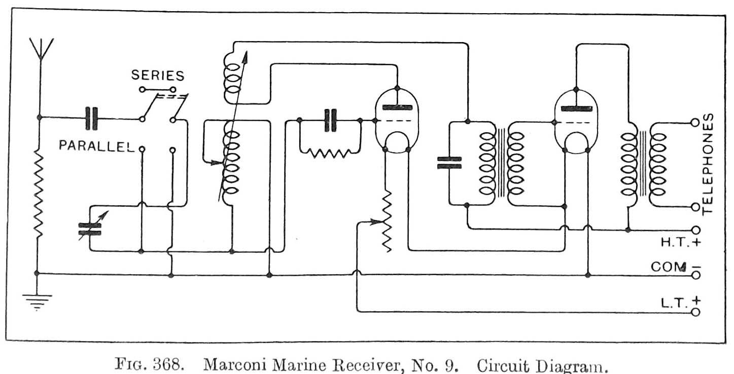
This is similar to receiver No. and is a two-valve instrument suitable for use in trawlers, and other small vessels. It employs a valve rectifier and note magnifier. The two valves are wired up with filaments in series in such a way as to provide a negative bias on the grid of the note magnifier. The note magnifier is transformer coupled and the output is through a telephone transformer to the telephones (headphones) .The receiver differs from the MR-5 in that it is tuned by means of a condenser. The circuit diagram is shown in Fig. 368. A switch is provided to enable the tuning condenser to be placed in series or in parallel with the aerial tuning inductance, and an auxiliary series condenser is provided to enable the receiver to tune to 200 metres. The wave-range of the receiver is from 200 to 3,000 metres. (1,500 to 100 KHz)
Image courtesy Handbook of Technical Instruction
Contributors and Credits:1) Lewis Bodkin <05bodkin555(at)gmail.com>
2) Handbook of Technical Instruction for For Wireless Telegraphists
Sept 19/19