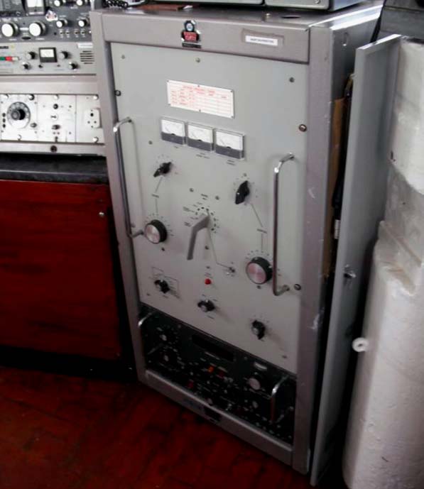 |
| Commandant SD fitted with the Synthesized Drive Unit. . (Photo courtesy Ships Nostalgia. web page) |
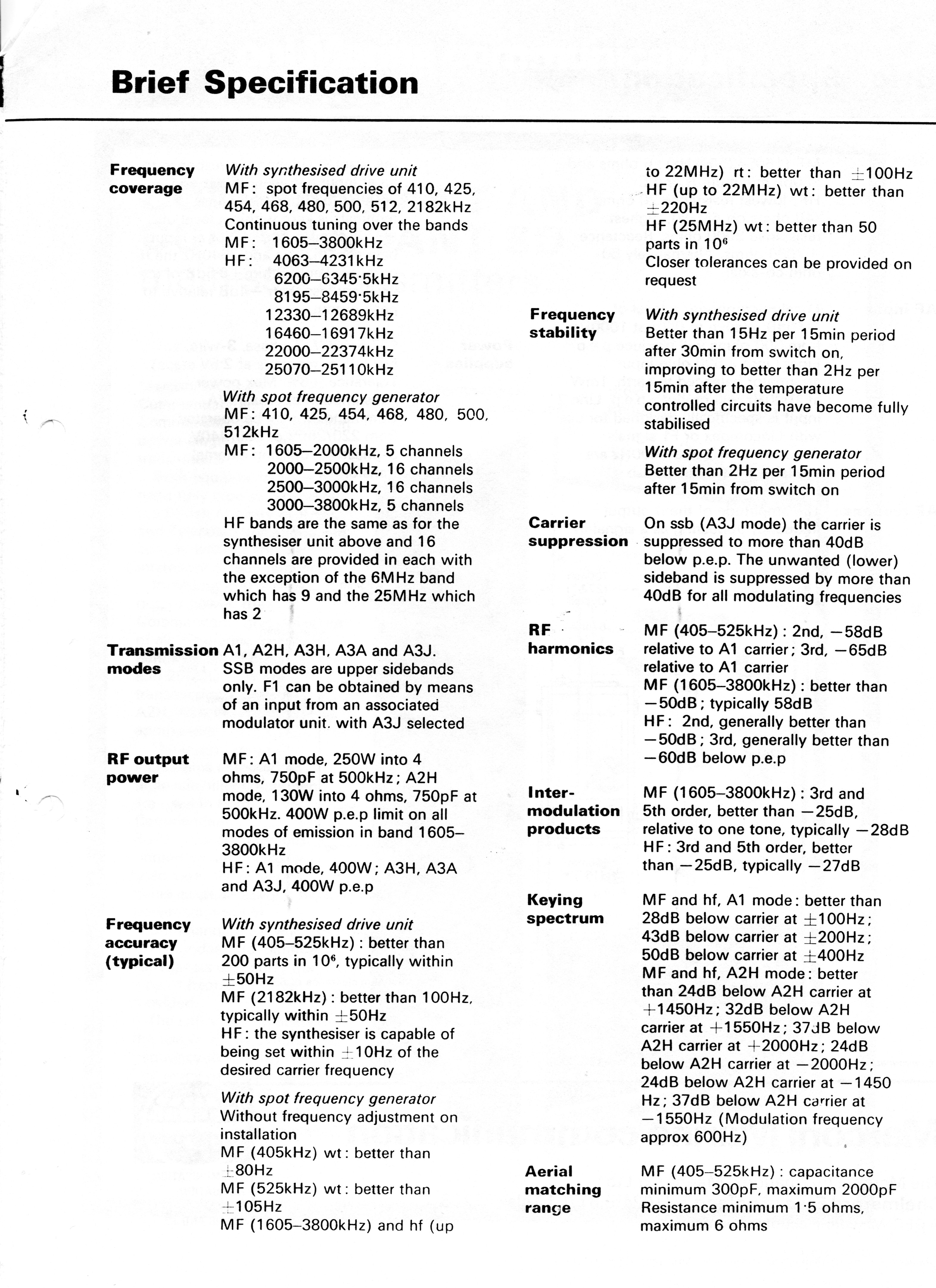
SPECIFICATIONSTechnology: SSB, solid state with valves in the RF output stage.
Frequency control: There is a choice of two frequency drives which are available for this transmitter. When the transmitter is fitted with a Synthesized Drive Unit , it is called the "Commandant SD". When fitted with a Spot Frequency Generator (a.k.a. the alternative drive unit), the transmitter is designated as a "Commandant"
The synthesizer permits operation on any of the marine frequencies without the need for any additional crystals Alternately, the Spot Frequency Generator is a crystal controlled frequency source using a partial frequency synthesis system. By using frequency division and multiplication of the the master oscillator, the greater portion of the radiated frequencies can be produced.. Individual crystals cover the remaining portion. Otherwise, both transmitters are identical in all other respects.
Frequency Coverage:
Spot frequencies: 410, 425,454,468, 480, 500, 512, and 2182 KHz .
Continuous tuning in the follpwing bands:MF:
1605 to 3500 KHzHF:
4063-4231 KHz
6200-6345 KHz
8195- 8459 KHz
12330-12689 KHz
16460-16917 KHz
22000-22374 KHz
25070·25110 KHzModes: A1, A2H, A3H, A3A and A3J- All SSB is upper sideband.
RF Output
MF A1 250 watts
MF A2H 130 watts
HF (1605 to 3800 kHz) - 400 watts PEP
HF bands A1 400 watts
HF Bands A3Hm A3A and A3J- 400 watts PEP
Mains power: 115 VAC, 3 phase or 440 VAC 3 phase depending on the information source.Dimensions: 25"W x 45"H x 24"D
Comments:
1) The Commandant was the first of Marconi Marine's transmitters to wear the two tone grey colours .
2) Select this link to see a partial specifications sheet for the Commandant
3) Either Commandant interfaces with a ship's telephone exchange
4) A block diagram of the Commandant can be found here. Provided by Andre Gorvel.
|
| Commandant SD fitted with the Synthesized Drive Unit. . (Photo courtesy Ships Nostalgia. web page) |
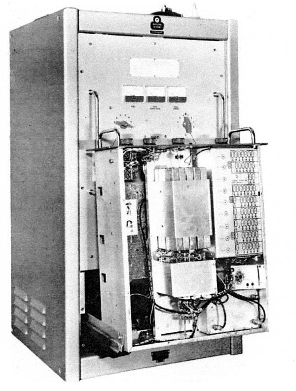 |
| The Commandant with the Spot Frequency Generator extended during maintenance. (Image courtesy Marconi Marine) |
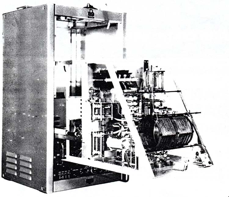 |
| Commandant with the RF deck extended. (Image courtesy Marconi Marine) |
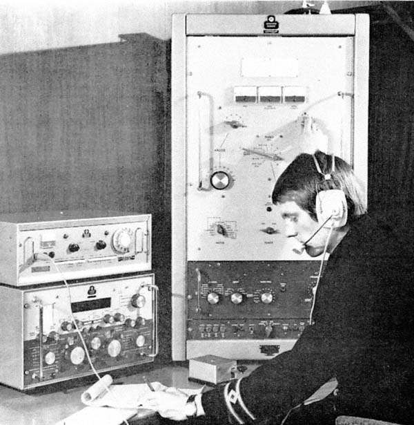 |
| The Commandant is shown alongside the companion Apollo receiver. This Commandant is fitted with the Spot Frequency Generator. (Image courtesy Marconi Marine) |
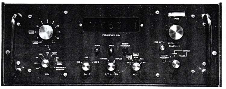 |
| Synthesized Drive Unit. The frequency of operation is indicated in a seven digit display. the (Image courtesy Marconi Marine) |
Contributors and Credits:
1) http://philpott.de/Pdf_book/Marine%20transmitters%20and%20receivers.pdf
2) http://www.shipsnostalgia.com/gallery/
showgallery.php?sortby=f&sorttime=9999&way=asc&thumbsonly=2&perpage=90&page=2&cat=530&ppuser=&thumbcheck=0
3) Ross Bradshaw [ross.bradshaw@mypostoffice.co.uk]
April 7/20