 |
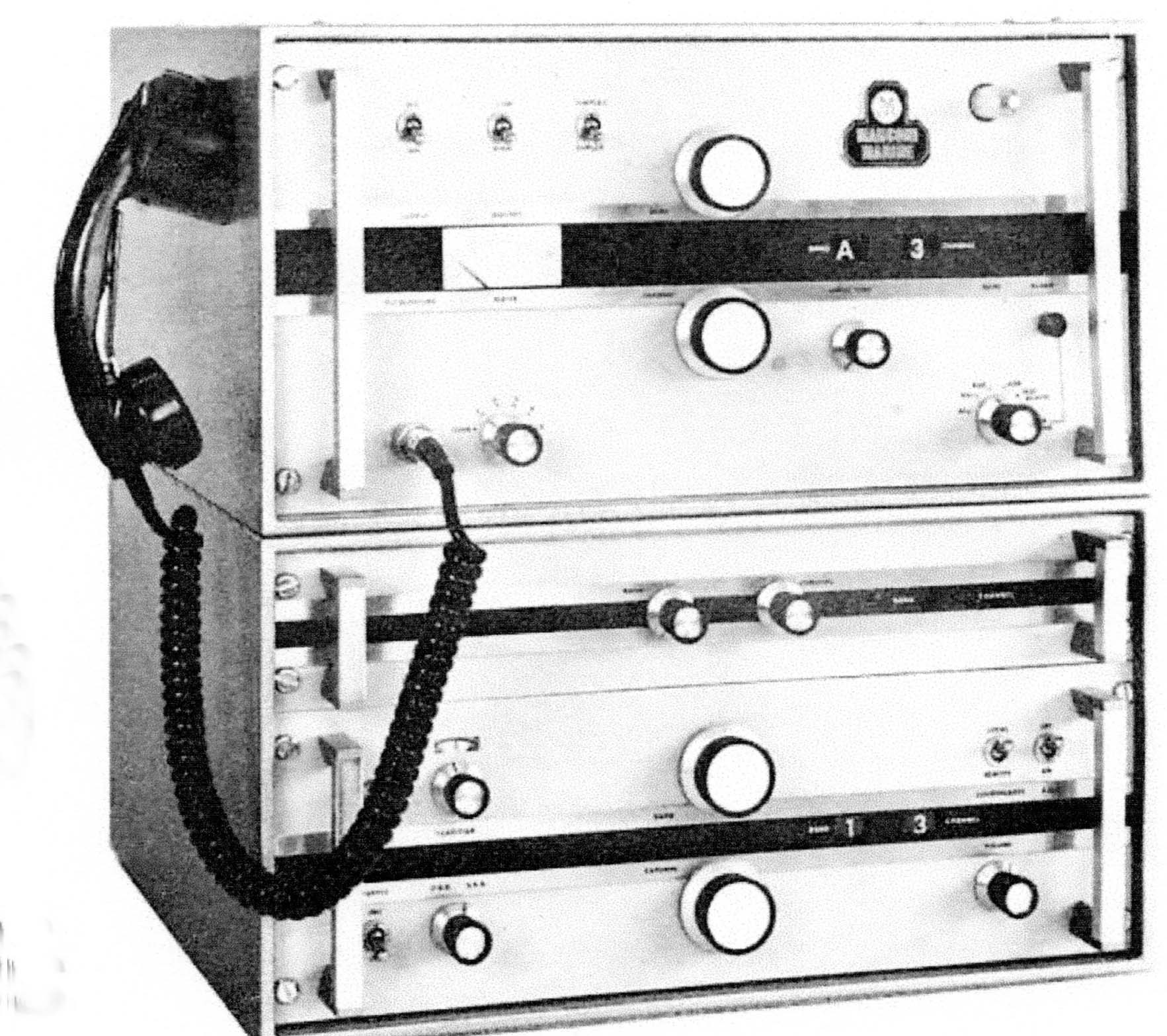
| Falcon 1 station. Physically speaking, it is virtually identical to Falcon II. (Image via Marconi Mariner Magazine.) |
SPECIFICATIONS:
Type: SSB transmitter receiver. The main difference between the Falcon I and the Falcon II is the frequency coverage provided. It is a solid state design except for the final RF stage which uses valves..
Falcon I covers the MF band from I.6 to 3.8 MHz
Falcon II covers this same band as above plus the marine bands at 4, 6, 8, 12, 16 and 22 MHz.FREQUENCIES
Both transmitters provide for twenty one frequencies in the MF band and the Falcon II provides five in the 6 MHz
band and eight frequencies per band in the 4, 8, 12, 16 and 22 MHz bands.Falcon IIs receiver has 2182 KHZ plus fourty-four DSB or eighty-eight SSB spot frequencies in the MF band and one
frequency in the LF band (150 to 300 kHz). The latter frequency band has been included so that local time signals
and national weather forecasts can be received.The Falcon II receiver provides the same frequencies as the Falcon I's receiver but has in addition five or ten SSB 6 MHz hand
and eight DSB or sixteen SSB channels in each of 4 ,8, 12 and 16 MHz bands.MODES
The modes of transmission for both Falcon I and Flacon II transmitters are A3A (SSB with partial carrier suppression),
A3H (SSB with re-inserted carrier), A3J (SSB with full carrier suppression) and A1 (CW) is also available.Modes of reception or both the Falcon I and Falcon II receivers are identical. They are A1 (MF only). A3. A3A. A3J
and A3H.RF POWER
Nominal power outputs are 120 watts for Falcon I and 150 watts for the Falcon II
MAINS POWER
24 volt batteries or 115/230 VAC. When the mains source is 110 VDC, an inverter is required.
DIMENSIONS
The Falcon I enclosure (only) is 16" H x 18" W x 17"D.
The Falcon II enclosure (only) is 19" H x 18" W x 17"D.
Power pack (separate unit) is 4"H x 10"W x 12"DCOMMENT: Also produced by Debeg/Telefunken under licence from Marconi Marine as type SE735.
|
| Falcon 1 station. Physically speaking, it is virtually identical to Falcon II. (Image via Marconi Mariner Magazine.) |
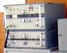 |
| Falcon I photo by John Rafter. |
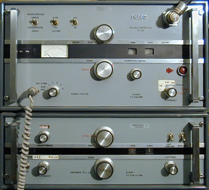 |
| This version of the Falcon station, namely the model SE735, was produced by Debeg/Telefunken under licence by Marconi. (From the seefunknetz.de web page) |
Peter G8LHF, used to work at the factory (Beehive Lane) making the Falcon I as an apprentice and then moved with the units to Marconi Marine all in Chelmsford. He adds the following."The receiver for both Falcon I and Falcon II was the same unit. However, the FII had a separate tray the same width and about 4 inches high mounted above the receiver. This was known as the "HF adaptor" thus enabling reception in the 6, 8, 12, 16 and 22 MHz bands. This is not to be confused with the "HF converter" which was mounted inside the transmitter and a real pain to align.The Falcon was designed outside of GEC / Marconi but I do not know where. Marconi bought the the rights to manufacture the Falcon I in 1971. In 1972, my first job after a year of basic training was to rake through the remains of the previous production run of the unknown production line and salvage coils, identify them, then box. This also included the recovery of crystal filters and any other high value components like ovens. The panels at that time were beige and worn by Falcon I's.
Marconi redesigned the receiver PCB's at a location called 3 Bays (old tyre depot) in London Road Baddow. I cannot comment on who / how / when the FII appeared only to state we started with FI's and then up skilled to FIIs."
Contributors and Credits:
1) Louis Hollerman <louis(at)holleman.demon.nl>
2) John Rafter <jaw(at)naples.net>
3) SE 735 photo http://www.seefunknetz.de/735.htm
4) Ross Bradshaw [ross.bradshaw@mypostoffice.co.uk]
MAa 27/20