 |
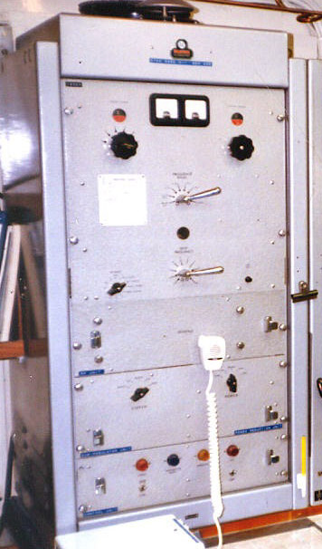
| Globespan transmitter fitted in CCGS Camsell circa 1985. The photo was taken not long before the ship was scrapped. The white microphone belongs to a maritime mobile VHF radio (Photo by Frank Statham) |
SPECIFICATIONS:Frequency range/power output/modes:
405 to 525 KHz in 7 preset channels 275 watts CW or MCW 1.6 to 3.8 MHz Radiotelephone 100 watts CW / MCW / AM 4 , 6, 8, 12, 16 and 22 MHz
marine bands with five preset
channels in each band.400 watts CW / AM Frequency control: Crystal
Power input - 115VAC, 50 to60Hz 3 phase
Weight - ?
Dimensions - ?
Circa: Leaflet REF TLT.52 for the Globespan Radiotelegraphy and Radiotelephony Transmitter (Type 1232A) is dated October 1954-15 so 1954 is the earliest in-service date for the Globespan.
|
| Globespan transmitter fitted in CCGS Camsell circa 1985. The photo was taken not long before the ship was scrapped. The white microphone belongs to a maritime mobile VHF radio (Photo by Frank Statham) |
Frank Statham describes some operational aspects of the Globespan transmitter . "Meters were situated at the top of the cabinet. One measured antenna current while the other measured currents in various circuits by use of a selectable switch.Big black knobs at the top - one for plate tuning and the other for antenna tuning. A white card was used to note control settings for various frequencies.
An upper handle selected the band while the lower handle switched the frequency within that band. This was a crystal controlled transmitter.
With reference to the he two switches on the second panel up: the right one stepped the power output while the left selected the mode (Phone, CW, MCW). The antenna selector panel (centre rack, at the top) could switch the transmitter into a dummy load. In series with the dummy load was a small lamp, one of the ones on that same panel, and over time the operator knew what sort of brilliance to expect on the various frequency bands. Crude but functional. If he was smart he could figure out the actual power by pulling out the manual and finding out the value of the resistance in the dummy load, factor in a couple of ohms here and there for the bulb and inductance , and do the I squared R, the I from the RF ammeter on the transmitter.
The bottom panel had two switches, one for system power (left) and the right was HT.
I believe the little black button on the top panel to the right of the lower 'handled' switch was a 'tune' button. It reduced the drive down so the operator wouldn't fry the output tubes while resonating the final stage. The operator could also peer in the little round window between the two 'handled' switches and see if the finals were cherry red or not.
A power supply resided directly below the transmitter. It was composed of several huge transformers and some rectifiers. Seems to me there was a big 'Mains' switch down there too".
Frank was also based in Victoria BC on Canadian weather ships. He goes on to describe marine CW operation in the MF and HF bands.
"On MF, the Coastal Station and the ship's station both kept watch on 500 kHz. If the ship had traffic for the coastal station she called them up on 500 kHz then switched over to the coastal station's working frequency. VAK's was 430 kHz. This is the way it was all around the world.
On HF there was no CW calling frequency. VAI was the only station on Canada's west coast fitted with HF CW. The vessel operator would tune his receiver to a published HF frequency for the coastal station and listen for that station's marker keying. If he didn't hear the marker on say 4 MHz, he would try 8 MHz, working his way up the band until he heard a good signal. The marker would be would be copied as: CQ CQ CQ DE VAI VAI VAI (plus some Q codes and requests for AMVER and WX) and repeated continuously.
Once the vessel operator decided on a band, he would tune his transmitter to one of the spot frequencies he had within that band and transmit something like VAI VAI VAI DE CGCW CGCW CGCW a few times.
Frequency reciprocity was relied on--if you could hear him, the odds are he would hear you.The fly in the ointment was that the coastal station never knew what frequency a ship would call on. There was a span of frequencies within each marine band on which he could expect a call. So the operator on
watch at VAI would slowly tune across the band segments listening for a call. If he heard you, he would disconnect his marking keyer and start pounding away on the hand key".
Contributors and Credits:
1).Frank Statham <fstatham(at)telus.net>
2) http://www.rnmuseumradarandcommunications2006.org.uk/MERCHANT%20SHIPS%20AND%20RFA%20FITS.pdf
3) John Dalgliesh <johndalgliesh(at)talktalk.net>
Nov 9/12